


iTNC 530
Table of contents
 Loading...
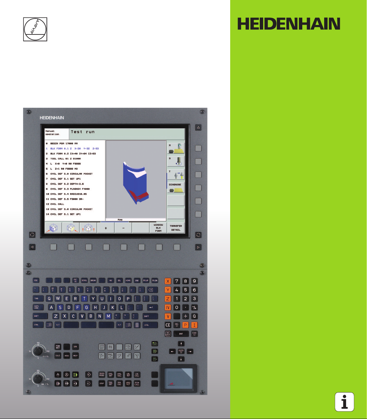
User’s Manual
HEIDENHAIN
Conversational Format
iTNC 530
NC Software
340 490-03
340 491-03
340 492-03
340 493-03
340 494-03
English (en)
9/2006
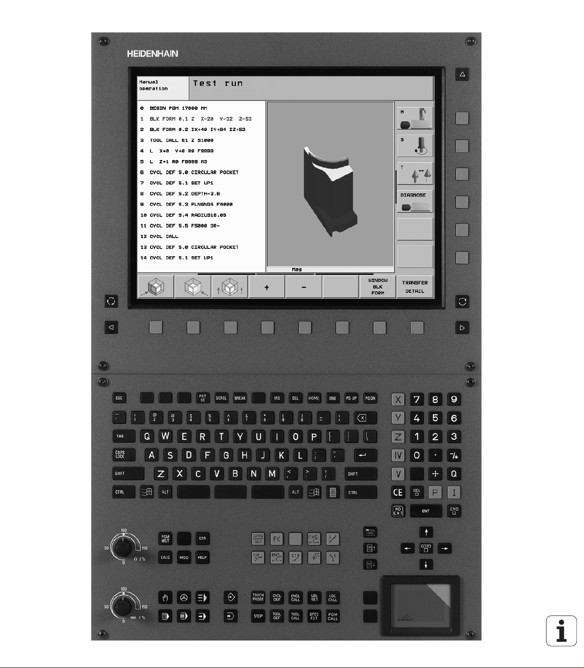
Controls on the visual display unit
Split screen layout
Switch between machining or
programming modes
Soft keys for selecting functions in
screen
Switches the soft-key rows
Typewriter keyboard for entering letters and symbols
File names
Comments
ISO
programs
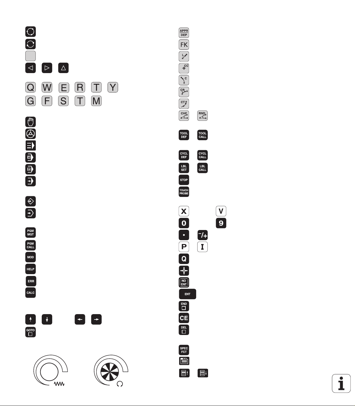
Machine operating modes
Manual Operation
Electronic Handwheel
smarT.NC
Positioning with Manual Data Input
Program Run, Single Block
Program Run, Full Sequence
Programming modes
Programming and Editing
Test Run
Program/file management, TNC functions
Select or delete programs and files
External data transfer
Define program call, select datum and point tables
Select the MOD function.
Displaying help texts for NC error messages
Display all current error messages
Pocket calculator
Moving the cursor, going directly to blocks, cycles and
parameter-functions
Go directly to blocks, cycles and parameter functions
Move highlight
Override control knobs for feed rate/spindle speed
50
100
0
1
F %
50
50
100
0
1
S %
50
Programming path movements
Approach/depart contour
FK free contour programming
Straight line
Circle center/pole for polar coordinates
Circle with center
Circle with radius
Circular arc with tangential connection
Chamfering/Corner rounding
Tool functions
Entering and calling tool length and radius
Cycles, subprograms and program section repeats
Define and call cycles
Enter and call labels for subprogramming and
program section repeats
Program stop in a program
Define touch probe cycles
Coordinate axes and numbers: Entering and editing
. . .
. . .
Decimal point / Reverse algebraic sign
Polar coordinate input/
Select coordinate axes or
enter them into the program
Numbers
Incremental dimensions
Q parameter programming/Q parameter status
Save actual position or values from calculator
Skip dialog questions, delete words
Confirm entry and resume dialog
Conclude block and exit entry
Clear the numerical entry or TNC error message
Abort dialog, delete program section
Special functions / smarT.NC
Show special functions
smarT.NC: Select next tab on form
smarT.NC: Select first input field in previous/
next frame


TNC Model, Software and Features
This manual describes functions and features provided by TNCs as of
the following NC software numbers.
TNC model NC software number
iTNC 530 340 490-03
iTNC 530 E 340 491-03
iTNC 530 340 492-03
iTNC 530 E 340 493-03
iTNC 530 programming station 340 494-03
The suffix E indicates the export version of the TNC. The export
version of the TNC has the following limitations:
Linear movement is possible in no more than 4 axes simultaneously.
The machine tool builder adapts the usable features of the TNC to his
machine by setting machine parameters. Some of the functions
described in this manual may not be among the features provided by
the TNC on your machine tool.
TNC functions that may not be available on your machine include:
Tool measurement with the TT
Please contact your machine tool builder to become familiar with the
features of your machine.
Many machine manufacturers, as well as HEIDENHAIN, offer
programming courses for the TNCs. We recommend these courses as
an effective way of enhancing your TNC programming skill and sharing
information and ideas with other TNC users.
TNC Model, Software and Features
Touch Probe Cycles User’s Manual:
All of the touch probe functions are described in a separate
manual. Please contact HEIDENHAIN if you need a copy of
this User’s Manual. Part number: 533 189-xx
smarT.NC user documentation:
The new smarT.NC operating mode is described in a
separate Pilot. Please contact HEIDENHAIN if you require
a copy of this Pilot. Part number: 533 191-xx.
HEIDENHAIN iTNC 530 5

Software options
The iTNC 530 features various software options that can be enabled
by you or your machine tool builder. Each option is to be enabled
separately and contains the following respective functions:
Software option 1
Cylinder surface interpolation (Cycles 27, 28, 29 and 39)
Feed rate in mm/min on rotary axes: M116
Tilting the machining plane (Cycle 19, PLANE function and 3-D ROT
soft key in the Manual operating mode)
Circle in 3 axes (with tilted working plane)
Software option 2
Block processing time 0.5 ms instead of 3.6 ms
5-axis interpolation
Spline interpolation
3-D machining:
M114: Automatic compensation of machine geometry when
TNC Model, Software and Features
working with tilted axes
M128: Maintaining the position of the tool tip when positioning
with tilted axes (TCPM)
FUNCTION TCPM: Maintaining the position of the tool tip when
positioning with tilted axes (TCPM) in selectable modes
M144: Compensating the machine’s kinematic configuration for
ACTUAL/NOMINAL positions at end of block
Additional parameters finishing/roughing and tolerance for
rotary axes in Cycle 32 (G62)
LN blocks (3-D compensation)
DCM software option Description
Function that monitors areas defined by the
machine manufacturer to prevent collisions.
DXF Converter software option Description
Extract contours from DXF files (R12 format). Page 277
Additional dialog language software
option
Function for enabling the conversational
languages Slovenian, Slovak, Norwegian,
Latvian, Estonian, Korean.
6
Page 93
Description
Page 711

Global Program Settings software option Description
Function for superimposing coordinate
transformations in the Program Run modes.
AFC software option Description
Function for adaptive feed-rate control for
optimizing the machining conditions during
series production.
Page 653
Page 660
TNC Model, Software and Features
HEIDENHAIN iTNC 530 7

Feature content level (upgrade functions)
Along with software options, significant further improvements of the
TNC software are managed via the Feature Content Level (FCL)
upgrade functions. Functions subject to the FCL are not available
simply by updating the software on your TNC.
All upgrade functions are available to you without
surcharge when you receive a new machine.
Upgrade functions are identified in the manual with FCL n, where n
indicates the sequential number of the feature content level.
You can purchase a code number in order to permanently enable the
FCL functions. For more information, contact your machine tool
builder or HEIDENHAIN.
FCL 3 functions Description
Touch probe cycle for 3-D probing Touch Probe Cycles
User’s Manual
Touch probe cycles for automatic datum
setting using the center point of a slot/
ridge
Feed-rate reduction for the machining of
TNC Model, Software and Features
contour pockets with the tool being in
full contact with the workpiece
PLANE function: Entry of axis angle Page 529
User documentation as a contextsensitive help system
smarT.NC: Programming of smarT.NC
and machining can be carried out
simultaneously
smarT.NC: Contour pocket on point
pattern
smarT.NC: Preview of contour
programs in the file manager
smarT.NC: Positioning strategy for
machining point patterns
FCL 2 functions Description
3-D line graphics Page 143
Touch Probe Cycles
User’s Manual
Page 435
Page 547
Page 116
smarT.NC Pilot
smarT.NC Pilot
smarT.NC Pilot
Virtual tool axis Page 92
USB support of block devices (memory
sticks, hard disks, CD-ROM drives)
Filtering of externally created contours Page 547
8
Page 128

FCL 2 functions Description
Possibility of assigning different depths
to each subcontour in the contour
formula
Page 463
DHCP dynamic IP-address
management
Touch-probe cycle for global setting of
touch-probe parameters
smarT.NC: Graphic support of block
scan
smarT.NC: Coordinate transformation smarT.NC Pilot
smarT.NC: PLANE function smarT.NC Pilot
Page 681
Touch Probe Cycles
User’s Manual
smarT.NC Pilot
Location of use
The TNC complies with the limits for a Class A device in accordance
with the specifications in EN 55022, and is intended for use primarily
in industrially-zoned areas.
Legal information:
This product uses open source software. Further information is
available on the control under
8 Programming and Editing operating mode
8 MOD function
8 LEGAL INFORMATION soft key
TNC Model, Software and Features
HEIDENHAIN iTNC 530 9

Functions included in 340 49x-01 new since the predecessor versions 340 422-xx and 340 423-xx
A new form-based operating mode, smarT.NC, has been
introduced. These cycles are described in a separate user’s
document. In connection with this the TNC operating panel was
enhanced. There are some new keys available for quicker navigation
within smarT.NC (see “Operating panel” on page 48).
The single-processor versions supports pointing devices (mice) via
the USB interface.
The tooth feed f
alternate feed entries (see “Possible feed rate input” on page 133).
New CENTERING cycle (see “CENTERING (Cycle 240)” on page
333)
New M function M150 for suppressing limit switch messages (see
“Suppress limit switch message: M150” on page 307)
M128 is now also permitted for mid-program startup (see “Mid-
program startup (block scan)” on page 645).
The number of available Q parameters was expanded to 2000 (see
“Principle and Overview” on page 566).
The number of available label numbers was expanded to 1000. Now
label names can be assigned as well (see “Labeling Subprograms
and Program Section Repeats” on page 550).
In the Q parameter functions FN9 to FN12 you can now also assign
TNC Model, Software and Features
label names as jump targets (see “If-Then Decisions with
Q Parameters” on page 575).
Selectively machine points from a point table (see “Hiding single
points from the machining process” on page 327).
The current time is also shown in the additional status display
window (see “General program information (PGM tab)” on page
55).
Several columns were added to the tool table (see “Tool table:
Standard tool data” on page 188).
The Test Run can now also be stopped and resumed within
machining cycles (see “Running a program test” on page 638).
and feed per revolution fu can now be defined as
z
10

New functions with 340 49x-02
DXF files can be opened directly on the TNC, in order to extract
contours into a plain-language program (see “Processing DXF Files
(Software Option)” on page 277).
3-D line graphics are now available in the Programming and Editing
operating mode (see “3-D Line Graphics (FCL 2 Function)” on page
143).
The active tool-axis direction can now be set as the active machining
direction for manual operation (see “Setting the current tool-axis
direction as the active machining direction (FCL 2 function)” on page
92).
The machine manufacturer can now define any areas on the
machine for collision monitoring (see “Dynamic Collision Monitoring
(Software Option)” on page 93).
Instead of the spindle speed S you can now define the cutting speed
Vc in m/min (see “Calling tool data” on page 198).
The TNC can now display freely definable tables in the familiar table
view or as forms (see “Switching between table and form view” on
page 220).
The function for converting FK programs to H was expanded.
Programs can now also be output in linearized format (see
“Converting FK programs into HEIDENHAIN conversational format”
on page 261).
You can filter contours that were created using external
programming systems (see “Filtering Contours (FCL 2 Function)”
on page 547).
For contours which you connect via the contour formula, you can
now assign separate machining depths for each subcontour (see
“Defining contour descriptions” on page 463).
The single-processor version now supports not only pointing
devices (mice), but also USB block devices (memory sticks, disk
drives, hard disks, CD-ROM drives) (see “USB devices on the TNC
(FCL 2 function)” on page 128).
TNC Model, Software and Features
HEIDENHAIN iTNC 530 11

New functions with 340 49x-03
The AFC function (Adaptive Feed Control) was introduced (see
“Adaptive Feed Control Software Option (AFC)” on page 660).
The global parameter settings function makes it possible to set
various transformations and settings in the program run modes (see
“Global Program Settings (Software Option)” on page 653).
The TNC now features a context-sensitive help system, the
TNCguide (see “The Context-Sensitive Help System TNCguide
(FCL3 Function)” on page 159).
Now you can extract point files from DXF files(see “Selecting and
storing machining positions” on page 285).
Now, in the DXF converter, you can divide or lengthen laterally
joined contour elements (see “Dividing, extending and shortening
contour elements” on page 284).
In the PLANE function the working plane can now also be defined
directly by its axis angle (see “Tilting the working plane through axis
angle: PLANE AXIAL (FCL 3 function)” on page 529).
Now, in Cycle 22 ROUGH-OUT, you can define a feed-rate reduction if
the tool is cutting on its entire circumference (FCL3 function, see
“ROUGH-OUT (Cycle 22),” page 435).
In Cycle 208 BORE MILLING, you can now choose between climb or
up-cut milling (see “BORE MILLING (Cycle 208)” on page 349).
String processing has been introduced in Q parameter programming
TNC Model, Software and Features
(see “String Parameters” on page 604).
A screen saver can be activated through machine parameter 7392
(see “General User Parameters” on page 706).
The TNC now also supports a network connection over the NFS V3
protocol (see “Ethernet Interface” on page 681).
The maximum manageable number of tools in a pocket table was
increased to 9999 (see “Pocket table for tool changer” on page
195).
Parallel programming is possible with smarT.NC(see “Select
smarT.NC programs” on page 116).
The system time can now be set through the MOD function (see
“Setting the System Time” on page 702).
12

Functions changed in 340 49x-01 since the predecessor versions 340 422-xx/340 423-xx
The layouts of the status display and additional status display were
redesigned (see “Status Displays” on page 52).
Software 340 490 no longer supports the small resolution in
combination with the BC 120 screen (see “Visual display unit” on
page 47).
New key layout of the TE 530 B keyboard unit (see “Operating
panel” on page 48)
The entry range for the EULPR precession angle in the PLANE EULER
function was expanded (see “Defining the Machining Plane with
Euler Angles: PLANE EULER” on page 522).
The plane vector in the PLANE EULER function no longer has to be
entered in standardized form (see “Defining the Machining Plane
with Two Vectors: VECTOR PLANE” on page 524).
Positioning behavior of the CYCL CALL PAT function modified (see
“Calling a cycle in connection with point tables” on page 329).
The tool types available for selection in the tool table were increased
in preparation for future functions.
Instead of the last 10, you can now choose from the last 15 selected
files (see “Choosing one of the last files selected” on page 120)
340 423-xx
HEIDENHAIN iTNC 530 13
Functions changed in 340 49x-01 since the predecessor versions 340 422-xx/

Functions changed in 340 49x-02
Access to the preset table was simplified. There are also new
possibilities for entering values in the preset table. See table
“Manually saving the datums in the preset table”.
In inch-programs, the function M136 (feed rate in 0.1 inch/rev) can
no longer be combined with the function FU.
340 423-xx
The feed-rate potentiometers of the HR 420 are no longer switched
over automatically when the handwheel is selected. The selection is
made via soft key on the handwheel. In addition, the pop-up window
for the active handwheel was made smaller, in order to improve the
view of the display beneath it (see “Potentiometer settings” on
page 72).
The maximum number of contour elements for SL cycles was
increased to 8192, so that much more complex contours can be
machined (see “SL Cycles” on page 426).
FN16: F-PRINT: The maximum number of Q-parameter values that
can be output per line in the format description file was increased to
32 (see “FN16: F-PRINT: Formatted output of texts or Q parameter
values” on page 584).
The soft keys START and START SINGLE BLOCK in the Program
Test mode of operation were switched, so that the soft-key
alignment is the same in all modes of operation (Programming and
Editing, smarT.NC, Test) (see “Running a program test” on page
638).
The design of the soft keys was revised completely.
Functions changed in 340 49x-01 since the predecessor versions 340 422-xx/
14

Changed functions with 340 49x-03
In Cycle 22 you can now define a tool name also for the coarse
roughing tool (see “ROUGH-OUT (Cycle 22)” on page 435).
In the PLANE function, an FMAX can now be programmed for the
automatic rotary positioning (see “Automatic positioning: MOVE/
TURN/STAY (entry is mandatory)” on page 532).
When running programs in which non-controlled axes are
programmed, the TNC now interrupts the program run and displays
a menu for returning to the programmed position (see
“Programming of non-controlled axes (counter axes)” on page 642).
The tool usage file now also includes the total machining time,
which serves as the basis for the progress display in percent in the
Program Run, Full Sequence mode (see “Tool usage test” on page
648).
The TNC now also takes the dwell time into account when
calculating the machining time in the Test Run mode (see
“Measuring the machining time” on page 635).
Arcs that are not programmed in the active working plane can now
also be run as spatial arcs (see “Circular path C around circle center
CC” on page 242).
The EDIT OFF/ON soft key on the pocket table can be deactivated
by the machine tool builder (see “Pocket table for tool changer” on
page 195).
The additional status display has been revised. The following
improvements have been introduced (see “Additional status
displays” on page 54):
A new overview page with the most important status displays
were introduced.
The individual status pages are now displayed as tabs (as in
smarT.NC). The individual tabs can be selected over the Page soft
keys or with the mouse.
The current run time of the program is shown in percent in a
moving-bar diagram.
The tolerance values set in Cycle 32 are displayed.
Active global program settings are displayed, provided that this
software option was enabled.
The status of the Adaptive Feed Control (AFC) is displayed,
provided that this software option was enabled.
340 423-xx
HEIDENHAIN iTNC 530 15
Functions changed in 340 49x-01 since the predecessor versions 340 422-xx/


Contents
Introduction
1
Manual Operation and Setup
Positioning with Manual Data Input
(MDI)
Programming: Fundamentals of File
Management, Programming Aids
Programming: Tools
Programming: Programming Contours
Programming: Miscellaneous Functions
Programming: Cycles
Programming: Special Functions
Programming: Subprograms and
Program Section Repeats
Programming: Q Parameters
Test Run and Program Run
MOD Functions
2
3
4
5
6
7
8
9
10
11
12
13
Tables and Overviews
iTNC 530 with Windows 2000 (Option)
HEIDENHAIN iTNC 530 17
14
15


1 Introduction ..... 45
1.1 The iTNC 530 ..... 46
Programming: HEIDENHAIN conversational, smarT.NC and ISO formats ..... 46
Compatibility ..... 46
1.2 Visual Display Unit and Operating Panel ..... 47
Visual display unit ..... 47
Screen layout ..... 47
Operating panel ..... 48
1.3 Modes of Operation ..... 49
Manual operation and electronic handwheel ..... 49
Positioning with Manual Data Input (MDI) ..... 49
Programming and editing ..... 50
Test Run ..... 50
Program Run, Full Sequence and Program Run, Single Block ..... 51
1.4 Status Displays ..... 52
“General” status display ..... 52
Additional status displays ..... 54
1.5 Accessories: HEIDENHAIN 3-D Touch Probes and Electronic Handwheels ..... 61
3-D touch probes ..... 61
HR electronic handwheels ..... 62
HEIDENHAIN iTNC 530 19

2 Manual Operation and Setup ..... 63
2.1 Switch-On, Switch-Off ..... 64
Switch-on ..... 64
Switch-off ..... 66
2.2 Moving the Machine Axes ..... 67
Note ..... 67
To traverse with the machine axis direction buttons: ..... 67
Incremental jog positioning ..... 68
Traversing with the HR 410 electronic handwheel ..... 69
HR 420 Electronic Handwheel ..... 70
2.3 Spindle Speed S, Feed Rate F and Miscellaneous Functions M ..... 76
Function ..... 76
Entering values ..... 76
Changing the spindle speed and feed rate ..... 77
2.4 Datum Setting (Without a 3-D Touch Probe) ..... 78
Note ..... 78
Preparation ..... 78
Datum setting with axis keys ..... 79
Datum management with the preset table ..... 80
2.5 Tilting the Working Plane (Software Option 1) ..... 87
Application, function ..... 87
Traversing the reference points in tilted axes ..... 88
Setting the datum in a tilted coordinate system ..... 89
Datum setting on machines with rotary tables ..... 89
Datum setting on machines with spindle-head changing systems ..... 90
Position display in a tilted system ..... 90
Limitations on working with the tilting function ..... 90
Activating manual tilting ..... 91
Setting the current tool-axis direction as the active machining direction (FCL 2 function) ..... 92
2.6 Dynamic Collision Monitoring (Software Option) ..... 93
Function ..... 93
Collision monitoring in the manual operating modes ..... 94
Collision monitoring in Automatic operation ..... 96
20

3 Positioning with Manual Data Input (MDI) ..... 97
3.1 Programming and Executing Simple Machining Operations ..... 98
Positioning with Manual Data Input (MDI) ..... 98
Protecting and erasing programs in $MDI ..... 101
HEIDENHAIN iTNC 530 21

4 Fundamentals of NC, File Management, Programming Aids, Pallet Management ..... 103
4.1 Fundamentals ..... 104
Position encoders and reference marks ..... 104
Reference system ..... 104
Reference system on milling machines ..... 105
Polar coordinates ..... 106
Absolute and incremental workpiece positions ..... 107
Setting the datum ..... 108
4.2 File Management: Fundamentals ..... 109
Files ..... 109
Data backup ..... 110
4.3 Working with the File Manager ..... 111
Directories ..... 111
Paths ..... 111
Overview: Functions of the file manager ..... 112
Calling the file manager ..... 113
Selecting drives, directories and files ..... 114
Creating a new directory (only possible on the TNC:\ drive) ..... 117
Copying a single file ..... 118
Copying a directory ..... 120
Choosing one of the last files selected ..... 120
Deleting a file ..... 121
Deleting a directory ..... 121
Marking files ..... 122
Renaming a file ..... 123
Additional functions ..... 123
Data transfer to or from an external data medium ..... 124
Copying files into another directory ..... 126
The TNC in a network ..... 127
USB devices on the TNC (FCL 2 function) ..... 128
4.4 Creating and Writing Programs ..... 129
Organization of an NC program in HEIDENHAIN conversational format ..... 129
Define the blank: BLK FORM ..... 129
Creating a new part program ..... 130
Programming tool movements in conversational format ..... 132
Actual position capture ..... 134
Editing a program ..... 135
The TNC search function ..... 139
22

4.5 Interactive Programming Graphics ..... 141
Generating / Not generating graphics during programming ..... 141
Generating a graphic for an existing program ..... 141
Block number display ON/OFF ..... 142
Erasing the graphic ..... 142
Magnifying or reducing a detail ..... 142
4.6 3-D Line Graphics (FCL 2 Function) ..... 143
Function ..... 143
Functions of the 3-D line graphics ..... 144
Highlighting NC blocks in the graphics ..... 146
Block number display ON/OFF ..... 146
Erasing the graphic ..... 146
4.7 Structuring Programs ..... 147
Definition and applications ..... 147
Displaying the program structure window / Changing the active window ..... 147
Inserting a structuring block in the (left) program window ..... 147
Selecting blocks in the program structure window ..... 147
4.8 Adding Comments ..... 148
Function ..... 148
Entering comments during programming ..... 148
Inserting comments after program entry ..... 148
Entering a comment in a separate block ..... 148
Functions for editing of the comment ..... 149
4.9 Creating Text Files ..... 150
Function ..... 150
Opening and exiting text files ..... 150
Editing texts ..... 151
Deleting and inserting characters, words and lines ..... 152
Editing text blocks ..... 153
Finding text sections ..... 154
4.10 Integrated Pocket Calculator ..... 155
Operation ..... 155
4.11 Immediate Help for NC Error Messages ..... 156
Displaying error messages ..... 156
Display HELP ..... 156
4.12 List of All Current Error Messages ..... 157
Function ..... 157
Show error list ..... 157
Calling the TNCguide help system ..... 157
Window contents ..... 158
4.13 The Context-Sensitive Help System TNCguide (FCL3 Function) ..... 159
Function ..... 159
Working with the TNCguide ..... 160
Downloading current help files ..... 164
HEIDENHAIN iTNC 530 23

4.14 Pallet Management ..... 166
Function ..... 166
Selecting a pallet table ..... 168
Leaving the pallet file ..... 168
Executing the pallet file ..... 169
4.15 Pallet Operation with Tool-Oriented Machining ..... 170
Function ..... 170
Selecting a pallet file ..... 174
Setting up the pallet file with the entry form ..... 175
Sequence of tool-oriented machining ..... 180
Leaving the pallet file ..... 181
Executing the pallet file ..... 181
24

5 Programming: Tools ..... 183
5.1 Entering Tool-Related Data ..... 184
Feed rate F ..... 184
Spindle speed S ..... 185
5.2 Tool Data ..... 186
Requirements for tool compensation ..... 186
Tool numbers and tool names ..... 186
Tool length L ..... 186
Tool radius R ..... 187
Delta values for lengths and radii ..... 187
Entering tool data into the program ..... 187
Entering tool data in the table ..... 188
Using an external PC to overwrite individual tool data ..... 194
Pocket table for tool changer ..... 195
Calling tool data ..... 198
Tool change ..... 199
5.3 Tool Compensation ..... 202
Introduction ..... 202
Tool length compensation ..... 202
Tool radius compensation ..... 203
5.4 Three-Dimensional Tool Compensation (Software Option 2) ..... 206
Introduction ..... 206
Definition of a normalized vector ..... 207
Permissible tool forms ..... 208
Using other tools: Delta values ..... 208
3-D compensation without tool orientation ..... 209
Face Milling: 3-D compensation with and without tool orientation ..... 210
Peripheral Milling: 3-D Radius Compensation with Workpiece Orientation ..... 212
5.5 Working with Cutting Data Tables ..... 214
Note ..... 214
Applications ..... 214
Table for workpiece materials ..... 215
Table for tool cutting materials ..... 216
Table for cutting data ..... 216
Data required for the tool table ..... 217
Working with automatic speed / feed rate calculation ..... 218
Changing the table structure ..... 219
Switching between table and form view ..... 220
Data transfer from cutting data tables ..... 221
Configuration file TNC.SYS ..... 221
HEIDENHAIN iTNC 530 25

6 Programming: Programming Contours ..... 223
6.1 Tool Movements ..... 224
Path functions ..... 224
FK Free Contour Programming ..... 224
Miscellaneous functions M ..... 224
Subprograms and program section repeats ..... 224
Programming with Q parameters ..... 224
6.2 Fundamentals of Path Functions ..... 225
Programming tool movements for workpiece machining ..... 225
6.3 Contour Approach and Departure ..... 229
Overview: Types of paths for contour approach and departure ..... 229
Important positions for approach and departure ..... 229
Approaching on a straight line with tangential connection: APPR LT ..... 232
Approaching on a straight line perpendicular to the first contour point: APPR LN ..... 232
Approaching on a circular path with tangential connection: APPR CT ..... 233
Approaching on a circular arc with tangential connection from a straight line to the contour: APPR LCT ..... 234
Departing on a straight line with tangential connection: DEP LT ..... 235
Departing on a straight line perpendicular to the last contour point: DEP LN ..... 235
Departure on a circular path with tangential connection: DEP CT ..... 236
Departing on a circular arc tangentially connecting the contour and a straight line: DEP LCT ..... 236
6.4 Path Contours—Cartesian Coordinates ..... 237
Overview of path functions ..... 237
Straight line L ..... 238
Inserting a chamfer CHF between two straight lines ..... 239
Corner rounding RND ..... 240
Circle center CC ..... 241
Circular path C around circle center CC ..... 242
Circular path CR with defined radius ..... 243
Circular path CT with tangential connection ..... 244
6.5 Path Contours—Polar Coordinates ..... 249
Overview ..... 249
Polar coordinate origin: Pole CC ..... 250
Straight line LP ..... 251
Circular path CP around pole CC ..... 251
Circular path CTP with tangential connection ..... 252
Helical interpolation ..... 253
26

6.6 Path Contours—FK Free Contour Programming ..... 258
Fundamentals ..... 258
Graphics during FK programming ..... 259
Converting FK programs into HEIDENHAIN conversational format ..... 261
Initiating the FK dialog ..... 262
Pole for FK programming ..... 262
Free programming of straight lines ..... 263
Free programming of circular arcs ..... 263
Input possibilities ..... 264
Auxiliary points ..... 267
Relative data ..... 268
6.7 Contour Movements—Spline Interpolation (Software Option 2) ..... 275
Function ..... 275
6.8 Processing DXF Files (Software Option) ..... 277
Function ..... 277
Opening a DXF file ..... 278
Basic settings ..... 279
Layer settings ..... 280
Specifying the reference point ..... 281
Selecting and saving a contour ..... 283
Selecting and storing machining positions ..... 285
Zoom function ..... 286
HEIDENHAIN iTNC 530 27

7 Programming: Miscellaneous-Functions ..... 287
7.1 Entering Miscellaneous Functions M and STOP ..... 288
Fundamentals ..... 288
7.2 Miscellaneous Functions for Program Run Control, Spindle and Coolant ..... 289
Overview ..... 289
7.3 Miscellaneous Functions for Coordinate Data ..... 290
Programming machine-referenced coordinates: M91/M92 ..... 290
Activating the most recently entered datum: M104 ..... 292
Moving to positions in a non-tilted coordinate system with a tilted working plane: M130 ..... 292
7.4 Miscellaneous Functions for Contouring Behavior ..... 293
Smoothing corners: M90 ..... 293
Insert rounding arc between straight lines: M112 ..... 294
Do not include points when executing non-compensated line blocks: M124 ..... 294
Machining small contour steps: M97 ..... 295
Machining open contours: M98 ..... 297
Feed rate factor for plunging movements: M103 ..... 298
Feed rate in millimeters per spindle revolution: M136 ..... 299
Feed rate for circular arcs: M109/M110/M111 ..... 299
Calculating the radius-compensated path in advance (LOOK AHEAD): M120 ..... 300
Superimposing handwheel positioning during program run: M118 ..... 302
Retraction from the contour in the tool-axis direction: M140 ..... 303
Suppressing touch probe monitoring: M141 ..... 304
Delete modal program information: M142 ..... 305
Delete basic rotation: M143 ..... 305
Automatically retract tool from the contour at an NC stop: M148 ..... 306
Suppress limit switch message: M150 ..... 307
7.5 Miscellaneous Functions for Rotary Axes ..... 308
Feed rate in mm/min on rotary axes A, B, C: M116 (software option 1) ..... 308
Shorter-path traverse of rotary axes: M126 ..... 309
Reducing display of a rotary axis to a value less than 360°: M94 ..... 310
Automatic compensation of machine geometry when working with tilted axes: M114 (software option 2) ..... 311
Maintaining the position of the tool tip when positioning with tilted axes (TCPM): M128 (software
option 2) ..... 312
Exact stop at corners with nontangential transitions: M134 ..... 315
Selecting tilting axes: M138 ..... 315
Compensating the machine’s kinematic configuration for ACTUAL/NOMINAL positions at end of block: M144
(software option 2) ..... 316
28

7.6 Miscellaneous Functions for Laser Cutting Machines ..... 317
Principle ..... 317
Output the programmed voltage directly: M200 ..... 317
Output voltage as a function of distance: M201 ..... 317
Output voltage as a function of speed: M202 ..... 318
Output voltage as a function of time (time-dependent ramp): M203 ..... 318
Output voltage as a function of time (time-dependent pulse): M204 ..... 318
HEIDENHAIN iTNC 530 29

8 Programming: Cycles ..... 319
8.1 Working with Cycles ..... 320
Machine-specific cycles ..... 320
Defining a cycle using soft keys ..... 321
Defining a cycle using the GOTO function ..... 321
Calling cycles ..... 323
Working with the secondary axes U/V/W ..... 325
8.2 Point Tables ..... 326
Function ..... 326
Creating a point table ..... 326
Hiding single points from the machining process ..... 327
Selecting a point table in the program ..... 328
Calling a cycle in connection with point tables ..... 329
8.3 Cycles for Drilling, Tapping and Thread Milling ..... 331
Overview ..... 331
CENTERING (Cycle 240) ..... 333
DRILLING (Cycle 200) ..... 335
REAMING (Cycle 201) ..... 337
BORING (Cycle 202) ..... 339
UNIVERSAL DRILLING (Cycle 203) ..... 341
BACK BORING (Cycle 204) ..... 343
UNIVERSAL PECKING (Cycle 205) ..... 346
BORE MILLING (Cycle 208) ..... 349
TAPPING NEW with floating tap holder (Cycle 206) ..... 351
RIGID TAPPING without a floating tap holder NEW (Cycle 207) ..... 353
TAPPING WITH CHIP BREAKING (Cycle 209) ..... 355
Fundamentals of thread milling ..... 357
THREAD MILLING (Cycle 262) ..... 359
THREAD MILLING/COUNTERSINKING (Cycle 263) ..... 361
THREAD DRILLING/MILLING (Cycle 264) ..... 365
HELICAL THREAD DRILLING/MILLING (Cycle 265) ..... 369
OUTSIDE THREAD MILLING (Cycle 267) ..... 373
8.4 Cycles for Milling Pockets, Studs and Slots ..... 382
Overview ..... 382
RECTANGULAR POCKET (Cycle 251) ..... 383
CIRCULAR POCKET (Cycle 252) ..... 388
SLOT MILLING (Cycle 253) ..... 392
CIRCULAR SLOT (Cycle 254) ..... 397
POCKET FINISHING (Cycle 212) ..... 402
STUD FINISHING (Cycle 213) ..... 404
CIRCULAR POCKET FINISHING (Cycle 214) ..... 406
CIRCULAR STUD FINISHING (Cycle 215) ..... 408
SLOT (oblong hole) with reciprocating plunge-cut (Cycle 210) ..... 410
CIRCULAR SLOT (oblong hole) with reciprocating plunge-cut (Cycle 211) ..... 413
30
Loading...