


 Loading...
User’s Manual
Touch Probe Cycles
iTNC 530
NC Software 340 490-03 340 491-03 340 492-03 340 493-03 340 494-03
English (en) 8/2006

TNC Model, Software and Features
This manual describes functions and features provided by TNCs as of the following NC software numbers.
TNC model |
NC software number |
iTNC 530 |
340 490-03 |
|
|
iTNC 530 E |
340 491-03 |
|
|
iTNC 530 |
340 492-03 |
|
|
iTNC 530 E |
340 493-03 |
|
|
iTNC 530 programming station |
340 494-03 |
|
|
The suffix E indicates the export version of the TNC. The export version of the TNC has the following limitations:
Linear movement is possible in no more than 4 axes simultaneously.
The machine tool builder adapts the useable features of the TNC to his machine by setting machine parameters. Some of the functions described in this manual may not be among the features provided by the TNC on your machine tool.
TNC functions that may not be available on your machine include:
Tool measurement with the TT
Please contact your machine tool builder to become familiar with the features of your machine.
Many machine manufacturers, as well as HEIDENHAIN, offer programming courses for the TNCs. We recommend these courses as an effective way of enhancing your TNC programming skill and sharing information and ideas with other TNC users.
User’s Manual:
All TNC functions that have no connection with touch probes are described in the User’s Manual of the
iTNC 530. Please contact HEIDENHAIN if you need a copy of this User’s Manual. Part number: 533 190-xx
smarT.NC user documentation:
The new smarT.NC operating mode is described in a separate Pilot. Please contact HEIDENHAIN if you require a copy of this Pilot. Part number: 533 191-xx.
TNC Model, Software and Features
HEIDENHAIN iTNC 530 |
3 |
TNC Model, Software and Features
Software options
The iTNC 530 features various software options that can be enabled by you or your machine tool builder. Each option is to be enabled separately and contains the following respective functions:
Software option 1
Cylinder surface interpolation (Cycles 27, 28, 29 and 39)
Feed rate in mm/min on rotary axes: M116
Tilting the machining plane (Cycle 19, PLANE function and 3-D ROT soft key in the Manual operating mode)
Circle in 3 axes (with tilted working plane)
Software option 2
Block processing time 0.5 ms instead of 3.6 ms
5-axis interpolation
Spline interpolation
3-D machining:
M114: Automatic compensation of machine geometry when working with tilted axes
M128: Maintaining the position of the tool tip when positioning with tilted axes (TCPM)
FUNCTION TCPM: Maintaining the position of the tool tip when positioning with tilted axes (TCPM) in selectable modes
M144: Compensating the machine’s kinematic configuration for ACTUAL/NOMINAL positions at end of block
Additional parameters finishing/roughing and tolerance for rotary axes in Cycle 32 (G62)
LN blocks (3-D compensation)
DCM Collision software option
Function which dynamically monitors areas defined by the machine manufacturer to prevent collisions.
Additional conversational language software option
Function for enabling the conversational languages Slovenian, Slovak, Norwegian, Latvian, Estonian, Korean.
DXF Converter software option
Extract contours from DXF files (R12 format).
4

Global Program Settings software option
Function for superimposing coordinate transformations in the Program Run modes.
AFC software option
Function for adaptive feed-rate control for optimizing the machining conditions during series production.
TNC Model, Software and Features
HEIDENHAIN iTNC 530 |
5 |
TNC Model, Software and Features
Feature content level (upgrade functions)
Along with software options, significant further improvements of the TNC software are managed via the Feature Content Level upgrade functions. Functions subject to the FCL are not available simply by updating the software on your TNC.
All upgrade functions are available to you without surcharge when you receive a new machine.
Upgrade functions are identified in the manual with FCL n, where n indicates the sequential number of the feature content level.
You can purchase a code number in order to permanently enable the FCL functions. For more information, contact your machine tool builder or HEIDENHAIN.
FCL 3 functions |
Description |
Touch probe cycle for 3-D probing |
Page 145 |
|
|
Touch probe cycles for automatic datum |
Page 67 |
setting using the center point of a slot/ |
|
ridge |
|
|
|
Feed-rate reduction for the machining of |
User’s Manual |
contour pockets with the tool being in |
|
full contact with the workpiece |
|
|
|
PLANE function: Entry of axis angle |
User’s Manual |
|
|
User documentation as a context- |
User’s Manual |
sensitive help system |
|
|
|
smarT.NC: Programming of smarT.NC |
User’s Manual |
and machining can be carried out |
|
simultaneously |
|
|
|
smarT.NC: Contour pocket on point |
smarT.NC Pilot |
pattern |
|
|
|
smarT.NC: Preview of contour |
smarT.NC Pilot |
programs in the file manager |
|
|
|
smarT.NC: Positioning strategy for |
smarT.NC Pilot |
machining point patterns |
|
|
|
FCL 2 functions |
Description |
3-D line graphics |
User’s Manual |
|
|
Virtual tool axis |
User’s Manual |
|
|
USB support of block devices (memory |
User’s Manual |
sticks, hard disks, CD-ROM drives) |
|
|
|
Filtering of externally created contours |
User’s Manual |
|
|
6

FCL 2 functions |
Description |
Possibility of assigning different depths |
User’s Manual |
to each subcontour in the contour |
|
formula |
|
|
|
DHCP dynamic IP-address |
User’s Manual |
management |
|
|
|
Touch-probe cycle for global setting of |
Page 149 |
touch-probe parameters |
|
|
|
smarT.NC: Graphic support of block |
smarT.NC Pilot |
scan |
|
|
|
smarT.NC: Coordinate transformation |
smarT.NC Pilot |
|
|
smarT.NC: PLANE function |
smarT.NC Pilot |
|
|
Location of use
The TNC complies with the limits for a Class A device in accordance with the specifications in EN 55022, and is intended for use primarily in industrially-zoned areas.
TNC Model, Software and Features
HEIDENHAIN iTNC 530 |
7 |

TNC Model, Software and Features
New functions of software 340 49x-02
New machine parameter for defining the positioning speed (see “Touch trigger probe, rapid traverse for positioning: MP6151” on page 23)
New machine parameter for consideration of basic rotation in Manual Operation (see “Consider a basic rotation in the Manual Operation mode: MP6166” on page 22)
Cycles 420 to 431 for automatic tool measurement were improved so that the measuring log can now also be displayed on the screen (see “Recording the results of measurement” on page 106)
A new cycle that enables you to set global touch probe parameters was introduced (see “FAST PROBING (touch probe cycle 441, ISO: G441, FCL-2 function)” on page 149)
New functions of software 340 49x-03
New cycle for setting a datum in the center of a slot (see “SLOT CENTER REFERENCE POINT (touch probe cycle 408, ISO: G408, FCL 3 function)” on page 67)
New cycle for setting a datum in the center of a ridge (see “RIDGE CENTER REFERENCE POINT (touch probe cycle 409, ISO: G409, FCL 3 function)” on page 70)
New 3-D probing cycle (see “MEASURING IN 3-D (touch probe cycle 4, FCL 3 function)” on page 145)
Cycle 401 now also allows you to compensate workpiece misalignment by rotating the rotary table (see “BASIC ROTATION from two holes (touch probe cycle 401, ISO: G401)” on page 50)
Cycle 402 now also allows you to compensate workpiece misalignment by rotating the rotary table (see “BASIC ROTATION over two studs (touch probe cycle 402, ISO: G402)” on page 52)
In the cycles for datum setting, the results of measurement are available in the Q parameters Q15X (see “Measurement results in Q parameters” on page 66)
8

Functions changed since the predecessor versions 340 422-xx and 340 423-xx
The management of more than one block of calibration data was changed (see “Managing more than one block of calibrating data” on page 32)
TNC Model, Software and Features
HEIDENHAIN iTNC 530 |
9 |
Contents
Introduction
Touch Probe Cycles in the Manual and
Electronic Handwheel Modes
Touch Probe Cycles for Automatic Workpiece Inspection
Touch Probe Cycles for Automatic Tool Measurement
1
2
3
4
HEIDENHAIN iTNC 530 |
11 |
|
|
|
|
|
|
|

1 Introduction ..... |
17 |
s•s˜ FmF•"d˜ mOp•h"›apm˜pm˜ p¤4^˜ •p*F˜ ©4dF’ ••••• sG¤m4›apm ••••• sG
p¤4^˜z•p*F˜4©4dF’˜am˜›^F˜ "m¤"d˜"m=˜ dF4›•pma4˜ "m=§^FFd˜hp=F’ ••••• snp¤4^˜z•p*F˜4©4dF’˜Op•˜"¤›ph"›a4˜pzF•"›apm ••••• sn
s•¢˜ FOp•F˜ p¤˜ ›"•›˜ p•camV˜§a›^˜ p¤4^˜ •p*F˜ ©4dF’ ••••• ¢s"¨ah¤h˜›•"¦F•’F˜›p˜›p¤4^˜zpam›9˜ –s•¬ ••••• ¢s"OF›©˜4dF"•"m4F˜›p˜›p¤4^˜zpam›9˜ –sT¬ ••••• ¢s•aFm›˜›^F˜amO•"•F=˜›p¤4^˜z•p*F˜›p˜›^F˜z•pV•"hhF=˜z•p*F˜=a•F4›apm9˜ –s–Q ••••• ¢spm’a=F•˜"˜*"’a4˜•p›"›apm˜am˜›^F˜ "m¤"d˜ zF•"›apm˜hp=F9˜ –s–– ••••• ¢¢¤d›azdF˜hF"’¤•FhFm›9˜ –s•¬ ••••• ¢¢pmOa=Fm4F˜am›F•¦"d˜Op•˜h¤d›azdF˜hF"’¤•FhFm›9˜ –s•s ••••• ¢¢p¤4^˜›•aVVF•˜z•p*F:˜z•p*amV˜OFF=˜•"›F9˜ –s¢¬ ••••• ¢•p¤4^˜›•aVVF•˜z•p*F:˜•"za=˜›•"¦F•’F˜Op•˜zp’a›apmamV9˜ –sQ¬ ••••• ¢•p¤4^˜›•aVVF•˜z•p*F:˜•"za=˜›•"¦F•’F˜Op•˜zp’a›apmamV9˜ –sQs ••••• ¢•¤mmamV˜›p¤4^˜z•p*F˜4©4dF’ ••••• ¢T
˜a ˜Q•¬ |
13 |

2 Touch Probe Cycles in the Manual and Electronic Handwheel Modes ..... |
25 |
¢•s˜ m›•p=¤4›apm ••••• ¢–¦F•¦aF§ ••••• ¢–
FdF4›amV˜z•p*F˜4©4dF’ ••••• ¢–F4p•=amV˜hF"’¤•F=˜¦"d¤F’˜O•ph˜›^F˜›p¤4^˜z•p*F˜4©4dF’ ••••• ¢••a›amV˜›^F˜hF"’¤•F=˜¦"d¤F’˜O•ph˜›p¤4^˜z•p*F˜4©4dF’˜am˜="›¤h˜›"*dF’ ••••• ¢G•a›amV˜›^F˜hF"’¤•F=˜¦"d¤F’˜O•ph˜›p¤4^˜z•p*F˜4©4dF’˜am˜›^F˜z•F’F›˜›"*dF ••••• ¢n
¢•¢˜ "da*•"›amV˜"˜ p¤4^˜ •aVVF•˜ •p*F ••••• •¬m›•p=¤4›apm ••••• •¬"da*•"›amV˜›^F˜FOOF4›a¦F˜dFmV›^ ••••• •¬
"da*•"›amV˜›^F˜FOOF4›a¦F˜•"=a¤’˜"m=˜4phzFm’"›amV˜4Fm›F•˜ha’"daVmhFm› ••••• •sa’zd"©amV˜4"da*•"›apm˜¦"d¤F’ ••••• •¢"m"VamV˜hp•F˜›^"m˜pmF˜*dp4c˜pO˜4"da*•"›amV˜="›" ••••• •¢
¢••˜ phzFm’"›amV˜ p•czaF4F˜ a’"daVmhFm› ••••• ••
m›•p=¤4›apm ••••• ••
F"’¤•amV˜›^F˜*"’a4˜•p›"›apm ••••• ••
"¦amV˜›^F˜*"’a4˜•p›"›apm˜am˜›^F˜z•F’F›˜›"*dF ••••• •Ta’zd"©amV˜"˜*"’a4˜•p›"›apm ••••• •Tp˜4"m4Fd˜"˜*"’a4˜•p›"›apm ••••• •T
¢•T˜ F››amV˜›^F˜ "›¤h˜§a›^˜"˜•_ ˜ p¤4^˜ •p*F ••••• •Qm›•p=¤4›apm ••••• •Q
"›¤h˜’F››amV˜am˜"m©˜"¨a’ ••••• •Qp•mF•˜"’˜="›¤hI¤’amV˜zpam›’˜"d•F"=©˜z•p*F=˜Op•˜"˜*"’a4˜•p›"›apm˜|’FF˜OaV¤•F˜"›˜•aV^›} ••••• •–p•mF•˜"’˜="›¤hI§a›^p¤›˜¤’amV˜zpam›’˜›^"›˜§F•F˜"d•F"=©˜z•p*F=˜Op•˜"˜*"’a4˜•p›"›apm ••••• •–a•4dF˜4Fm›F•˜"’˜="›¤h ••••• ••
Fm›F•˜damF˜"’˜="›¤h ••••• •GF››amV˜="›¤h˜zpam›’˜¤’amV˜^pdF’—4©dam=•a4"d˜’›¤=’ ••••• •n
¢•Q˜ F"’¤•amV˜ p•czaF4F’˜§a›^˜"˜•_ ˜ p¤4^˜ •p*F ••••• T¬m›•p=¤4›apm ••••• T¬
p˜Oam=˜›^F˜4pp•=am"›F˜pO˜"˜zp’a›apm˜pm˜"m˜"daVmF=˜§p•czaF4F9 ••••• T¬am=amV˜›^F˜4pp•=am"›F’˜pO˜"˜4p•mF•˜am˜›^F˜§p•camV˜zd"mF ••••• T¬p˜hF"’¤•F˜§p•czaF4F˜=ahFm’apm’ ••••• Tsp˜Oam=˜›^F˜"mVdF˜*F›§FFm˜›^F˜"mVdF˜•FOF•Fm4F˜"¨a’˜"m=˜"˜’a=F˜pO˜›^F˜§p•czaF4F ••••• T¢
¢•–˜ ’amV˜›^F˜ p¤4^˜ •p*F˜ ¤m4›apm’˜§a›^˜ F4^"ma4"d˜ •p*F’˜p•˜ a"d˜ "¤VF’ ••••• T•m›•p=¤4›apm ••••• T•
14

3 Touch Probe Cycles for Automatic Workpiece Inspection ..... 45
••s˜ F"’¤•amV˜ p•czaF4F˜ a’"daVmhFm› ••••• T–¦F•¦aF§ ••••• T–
^"•"4›F•a’›a4’˜4phhpm˜›p˜"dd˜›p¤4^˜z•p*F˜4©4dF’˜Op•˜hF"’¤•amV˜§p•czaF4F˜ha’"daVmhFm› ••••• T•
˜ ˜|›p¤4^˜z•p*F˜4©4dF˜T¬¬:˜ 9 T¬¬} ••••• TG
˜ ˜O•ph˜›§p˜^pdF’˜|›p¤4^˜z•p*F˜4©4dF˜T¬s:˜ 9˜ T¬s} ••••• Q¬
˜ ˜p¦F•˜›§p˜’›¤=’˜|›p¤4^˜z•p*F˜4©4dF˜T¬¢:˜ 9˜ T¬¢} ••••• Q¢
˜ ˜4phzFm’"›apm˜¦a"˜•p›"•©˜"¨a’˜|›p¤4^˜z•p*F˜4©4dF˜T¬•:˜ 9 T¬•} ••••• QQ
˜ ˜|›p¤4^˜z•p*F˜4©4dF T¬T:˜ 9 T¬T} ••••• QGphzFm’"›amV˜§p•czaF4F˜ha’"daVmhFm›˜*©˜•p›"›amV˜›^F˜ ˜"¨a’˜|›p¤4^˜z•p*F˜4©4dF˜T¬Q:˜ 9 T¬Q} ••••• Qn
••¢˜ ¤›ph"›a4˜ "›¤h˜ F››amV ••••• –•¦F•¦aF§ ••••• –•
^"•"4›F•a’›a4’˜4phhpm˜›p˜"dd˜›p¤4^˜z•p*F˜4©4dF’˜Op•˜="›¤h˜’F››amV ••••• –QF"’¤•FhFm›˜•F’¤d›’˜am˜ ˜z"•"hF›F•’ ••••• ––
˜ ˜ ˜ ˜|›p¤4^˜z•p*F˜4©4dF T¬G:˜ 9˜ T¬G:˜ ˜•˜O¤m4›apm} ••••• –•
˜ ˜ ˜ ˜|›p¤4^˜z•p*F˜4©4dF T¬n:˜ 9˜ T¬n:˜ ˜•˜O¤m4›apm} ••••• •¬
˜ ˜ ˜ ˜ ˜|›p¤4^ z•p*F˜4©4dF˜Ts¬:˜ 9˜ Ts¬} ••••• ••
˜ ˜ ˜ ˜ ˜|›p¤4^˜z•p*F˜4©4dF˜Tss:˜ 9˜ Tss} ••••• •–
˜ ˜ ˜ ˜ ˜|›p¤4^˜z•p*F˜4©4dF˜Ts¢:˜ 9˜ Ts¢} ••••• •n
˜ ˜ ˜ ˜ ˜|›p¤4^ z•p*F˜4©4dF˜Ts•:˜ 9˜ Ts•} ••••• G¢
˜ ˜ ˜ ˜ ˜|›p¤4^ z•p*F˜4©4dF˜TsT:˜ 9˜ TsT} ••••• GQ
˜ ˜ ˜ ˜ ˜|›p¤4^˜z•p*F˜4©4dF˜TsQ:˜ 9˜ TsQ} ••••• GG
˜ ˜ ˜|›p¤4^˜z•p*F˜4©4dF˜Ts–:˜ 9˜ Ts–} ••••• ns
˜ ˜ ˜ ˜ ˜|›p¤4^˜z•p*F˜4©4dF˜Ts•:˜ 9˜ Ts•} ••••• nT
˜ ˜ ˜ ˜T˜ ˜|›p¤4^ z•p*F˜4©4dF˜TsG:˜ 9˜ TsG} ••••• n–
˜ ˜ ˜ ˜|›p¤4^˜z•p*F˜4©4dF˜Tsn:˜ 9˜ Tsn} ••••• nn
˜a ˜Q•¬ |
15 |

•••˜ ¤›ph"›a4˜ p•czaF4F˜ F"’¤•FhFm› ••••• s¬Q¦F•¦aF§ ••••• s¬QF4p•=amV˜›^F˜•F’¤d›’˜pO˜hF"’¤•FhFm› ••••• s¬–F"’¤•FhFm›˜•F’¤d›’˜am˜ ˜z"•"hF›F•’ ••••• s¬Gd"’’aOa4"›apm˜pO˜•F’¤d›’ ••••• s¬GpdF•"m4F˜hpma›p•amV ••••• s¬G
ppd˜hpma›p•amV ••••• s¬nFOF•Fm4F˜’©’›Fh˜Op•˜hF"’¤•FhFm›˜•F’¤d›’ ••••• s¬n
˜ ˜|›p¤4^˜z•p*F˜4©4dF˜¬:˜ 9 QQ} ••••• ss¬
˜ ˜|›p¤4^˜z•p*F˜4©4dF˜s} ••••• sss
˜ ˜|›p¤4^˜z•p*F˜4©4dF˜T¢¬:˜ 9 T¢¬} ••••• ss¢
˜ ˜|›p¤4^˜z•p*F˜4©4dF˜T¢s:˜ 9 T¢s} ••••• ssT
˜ ˜ ˜|›p¤4^˜z•p*F˜4©4dF T¢¢:˜ 9˜ T¢¢} ••••• ss•
˜ ˜ ˜ ˜|›p¤4^ z•p*F˜4©4dF T¢•:˜ 9˜ T¢•} ••••• s¢¬
˜ ˜ ˜ ˜|›p¤4^ z•p*F˜4©4dF˜T¢T:˜ 9˜ T¢T} ••••• s¢•
˜ ˜ ˜|›p¤4^ z•p*F 4©4dF T¢Q:˜ 9˜ T¢Q} ••••• s¢–
˜ ˜ ˜|›p¤4^˜z•p*F˜4©4dF T¢–:˜ 9˜ T¢–} ••••• s¢G
˜ ˜|›p¤4^˜z•p*F˜4©4dF˜T¢•:˜ 9˜ T¢•} ••••• s•¬
˜ ˜ ˜ ˜|›p¤4^ z•p*F 4©4dF˜T•¬:˜ 9˜ T•¬} ••••• s•¢
˜ ˜|›p¤4^˜z•p*F˜4©4dF’˜T•s:˜ 9˜ T•s} ••••• s•Q ••T˜ zF4a"d˜ ©4dF’ ••••• sTs
¦F•¦aF§ ••••• sTs
˜ ˜|›p¤4^˜z•p*F˜4©4dF˜¢} ••••• sT¢
˜ ˜ ˜|›p¤4^˜z•p*F˜4©4dF˜n} ••••• sT•
˜|›p¤4^˜z•p*F˜4©4dF˜•} ••••• sTT
˜ ˜•_ ˜|›p¤4^˜z•p*F˜4©4dF˜T:˜ ˜•˜O¤m4›apm} ••••• sTQ
˜ ˜ ˜|›p¤4^˜z•p*F˜4©4dF ˜TT¬:˜ 9˜ TT¬} ••••• sT•
˜ ˜|›p¤4^˜z•p*F˜4©4dF TTs:˜ 9 TTs:˜ _¢˜O¤m4›apm} ••••• sTn
4 Touch Probe Cycles for Automatic Tool Measurement ..... |
151 |
T•s˜ ppd˜ F"’¤•FhFm›˜§a›^˜›^F˜ ˜ ppd˜ p¤4^˜ •p*F ••••• sQ¢¦F•¦aF§ ••••• sQ¢
F››amV˜›^F˜h"4^amF˜z"•"hF›F•’ ••••• sQ¢m›•aF’˜am˜›^F˜›ppd˜›"*dF˜ • ••••• sQTa’zd"©˜›^F˜•F’¤d›’˜pO˜hF"’¤•FhFm› ••••• sQQ
T•¢˜ ¦"ad"*dF˜ ©4dF’ ••••• sQ–¦F•¦aF§ ••••• sQ–
aOOF•Fm4F’˜*F›§FFm˜ ©4dF’˜•s˜›p˜••˜"m=˜ ©4dF’ TGs˜›p˜TG• ••••• sQ–"da*•"›amV˜›^F˜ ˜|›p¤4^˜z•p*F˜4©4dF˜•¬˜p•˜TG¬:˜ 9˜ TG¬} ••••• sQ•F"’¤•amV˜›^F˜›ppd˜dFmV›^˜|›p¤4^˜z•p*F˜4©4dF ˜•s˜p•˜TGs:˜ 9˜ TGs} ••••• sQGF"’¤•amV˜›^F˜›ppd˜•"=a¤’˜|›p¤4^˜z•p*F˜4©4dF˜•¢˜p•˜TG¢:˜ 9˜ TG¢} ••••• s–¬F"’¤•amV˜›^F˜›ppd˜•"=a¤’˜|›p¤4^˜z•p*F˜4©4dF˜••˜p•˜TG•:˜ 9˜ TG•} ••••• s–¢
16
1
Introduction
1.1 General Information on Touch Probe Cycles
1.1General Information on Touch Probe Cycles
The TNC must be specially prepared by the machine tool builder for the use of a 3-D touch probe.
If you are carrying out measurements during program run, be sure that the tool data (length, radius) can be used from the calibrated data or from the last TOOL CALL block (selected with MP7411).
Function
Whenever the TNC runs a touch probe cycle, the 3-D touch probe approaches the workpiece in one linear axis. This is also true during an active basic rotation or with a tilted working plane. The machine tool builder determines the probing feed rate in a machine parameter (see
“Before You Start Working with Touch Probe Cycles” later in this Z
chapter).
Y
When the probe stylus contacts the workpiece,
the 3-D touch probe transmits a signal to the TNC: the coordinates of the probed position are stored,
the touch probe stops moving, and
returns to its starting position at rapid traverse.
If the stylus is not deflected within a distance defined in MP 6130, the TNC displays an error message.
X
F
F MAX
18 |
1 Introduction |
Touch probe cycles in the Manual and Electronic Handwheel modes
In the Manual and Electronic Handwheel operating modes, the TNC provides touch probe cycles that allow you to:
Calibrate the touch probe
Compensate workpiece misalignment
Set datums
Touch probe cycles for automatic operation
Besides the touch probe cycles, which you can use in the Manual and Electronic Handwheel modes, the TNC provides numerous cycles for a wide variety of applications in automatic mode:
Calibrating the touch probe (Chapter 3)
Compensating workpiece misalignment (Chapter 3)
Setting datums (Chapter 3)
Automatic workpiece inspection (Chapter 3)
Automatic workpiece measurement (Chapter 4)
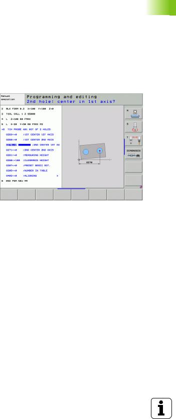
You can program the touch probe cycles in the Programming and Editing operating mode via the TOUCH PROBE key. Like the most recent fixed cycles, touch probe cycles use Q parameters with numbers of 400 and above as transfer parameters. Parameters with the same function that the TNC requires in several cycles always have the same number: For example, Q260 is always assigned the clearance height, Q261 the measuring height, etc.
To simplify programming, the TNC shows a graphic during cycle definition. In the graphic, the parameter that needs to be entered is highlighted (see figure at right).
1.1 General Information on Touch Probe Cycles
HEIDENHAIN iTNC 530 |
19 |
1.1 General Information on Touch Probe Cycles
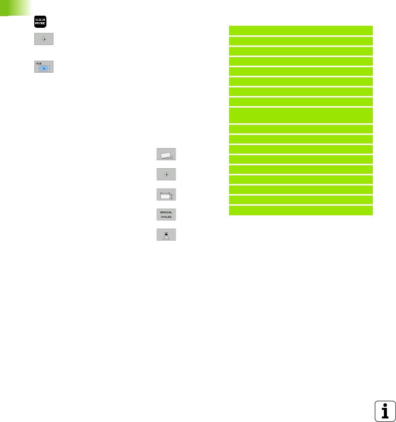
Defining the touch probe cycle in the Programming and Editing mode of operation
8 The soft-key row shows all available touch probe functions divided into groups.
8Select the desired probe cycle, for example datum setting. Digitizing cycles and cycles for automatic tool measurement are available only if your machine has been prepared for them.
8Select a cycle, e.g. datum setting at pocket. The TNC initiates the programming dialog and asks for all required input values. At the same time a graphic of the input parameters is displayed in the right screen window. The parameter that is asked for in the dialog prompt is highlighted.
8Enter all parameters requested by the TNC and conclude each entry with the ENT key.
8The TNC ends the dialog when all required data has been entered.
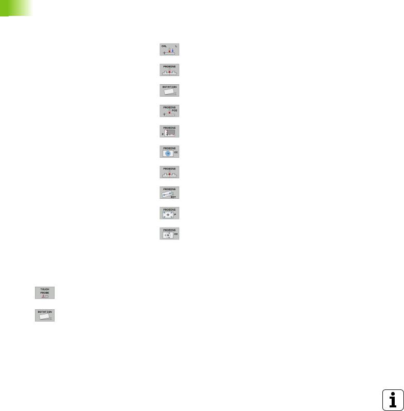
Group of measuring cycles |
Soft key |
Page |
Cycles for automatic measurement and |
|
Page 46 |
compensation of workpiece misalignment |
|
|
|
|
|
Cycles for automatic datum setting |
|
Page 63 |
|
|
|
Cycles for automatic workpiece |
|
Page 105 |
inspection |
|
|
|
|
|
Calibration cycles, special cycles |
|
Page 141 |
|
|
|
Cycles for automatic tool measurement |
|
Page 152 |
(enabled by the machine tool builder) |
|
|
|
|
|
Example: NC blocks
5 TCH PROBE 410 DATUM INSIDE RECTAN.
Q321=+50 ;CENTER IN 1ST AXIS
Q322=+50 ;CENTER IN 2ND AXIS
Q323=60 ;1ST SIDE LENGTH
Q324=20 ;2ND SIDE LENGTH
Q261=-5 ;MEASURING HEIGHT
;SET-UP CLEARANCE
;CLEARANCE HEIGHT
;TRAVERSE TO CLEARANCE HEIGHT
;NO. IN TABLE
;DATUM
;DATUM
;MEAS. VALUE TRANSFER
;PROBE IN TS AXIS
;1ST CO. FOR TS AXIS
;2ND CO. FOR TS AXIS
;3RD CO. FOR TS AXIS
;DATUM
20 |
1 Introduction |
1.2Before You Start Working with Touch Probe Cycles
To make it possible to cover the widest possible range of applications, machine parameters enable you to determine the behavior common to all touch probe cycles:
Maximum traverse to touch point: MP6130
If the stylus is not deflected within the path defined in MP6130, the TNC outputs an error message.
Safety clearance to touch point: MP6140
In MP6140 you define how far from the defined (or calculated) touch point the TNC is to pre-position the touch probe. The smaller the value you enter, the more exactly must you define the touch point position. In many touch probe cycles you can also define a setup clearance in addition that is added to Machine Parameter 6140.
Orient the infrared touch probe to the programmed probe direction: MP6165
To increase measuring accuracy, you can use MP 6165 = 1 to have an infrared touch probe oriented in the programmed probe direction before every probe process. In this way the stylus is always deflected in the same direction.
If you change MP6165, you must recalibrate the touch probe.
1.2 Before You Start Working with Touch Probe Cycles
HEIDENHAIN iTNC 530 |
21 |

1.2 Before You Start Working with Touch Probe Cycles
Consider a basic rotation in the Manual Operation mode: MP6166
Set MP 6166 = 1 for the TNC to consider an active basic rotation during the probing process (the workpiece is approached along an angular path if required) to ensure that the measuring accuracy for probing individual positions is also increased in Setup mode.
This feature is not active during the following functions in the Manual Operation mode:
Calibrate length
Calibrate radius
Measure basic rotation
Multiple measurement: MP6170
To increase measuring certainty, the TNC can run each probing process up to three times in sequence. If the measured position values differ too greatly, the TNC outputs an error message (the limit value is defined in MP6171). With multiple measurement it is possible to detect random errors, e.g., from contamination.
If the measured values lie within the confidence interval, the TNC saves the mean value of the measured positions.
Confidence interval for multiple measurement: MP6171
In MP6171 you store the value by which the results may differ when you make multiple measurements. If the difference in the measured values exceeds the value in MP6171, the TNC outputs an error message.
22 |
1 Introduction |
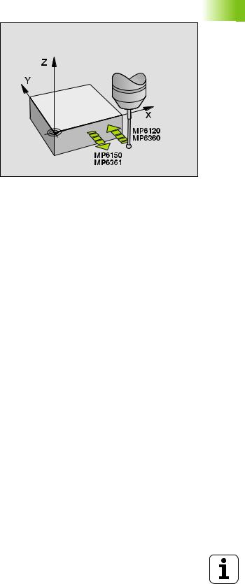
Touch trigger probe, probing feed rate: MP6120
In MP6120 you define the feed rate at which the TNC is to probe the workpiece.
Touch trigger probe, rapid traverse for positioning: MP6150
In MP6150 you define the feed rate at which the TNC pre-positions the touch probe, or positions it between measuring points.
Touch trigger probe, rapid traverse for positioning: MP6151
In MP6151 you define whether the TNC is to position the touch probe at the feed rate defined in MP6150 or at rapid traverse.
Input value = 0: Position at feed rate from MP6150
Input value = 1: Pre-position at rapid traverse
1.2 Before You Start Working with Touch Probe Cycles
HEIDENHAIN iTNC 530 |
23 |

1.2 Before You Start Working with Touch Probe Cycles
Running touch probe cycles
All touch probe cycles are DEF active. This means that the TNC runs the cycle automatically as soon as the TNC executes the cycle definition in the program run.
Make sure that at the beginning of the cycle the compensation data (length, radius) from the calibrated data or from the last TOOL CALL block are active (selection via MP7411, see the User’s Manual of the iTNC 530, “General User Parameters”).
You can also run the touch probe cycles 408 to 419 during an active basic rotation. Make sure, however, that the basic rotation angle does not change when you use Cycle 7 DATUM SHIFT with datum tables after the measuring cycle.
Touch probe cycles with a number greater than 400 position the touch probe according to a positioning logic:
If the current coordinate of the south pole of the stylus is less than the coordinate of the clearance height (defined in the cycle), the TNC retracts the touch probe in the probe axis to the clearance height and then positions it in the working plane to the first starting position.
If the current coordinate of the south pole of the stylus is greater than the coordinate of the clearance height, the TNC first positions the probe in the working plane to the first starting position and then moves it immediately to the measuring height in the touch probe axis.
24 |
1 Introduction |
2
Touch Probe Cycles
in the Manual and
Electronic Handwheel Modes
2.1 Introduction
2.1 Introduction
Overview
The following touch probe cycles are available in the Manual mode:
Function |
Soft key |
Page |
Calibrate the effective length |
|
Page 30 |
|
|
|
Calibrate the effective radius |
|
Page 31 |
|
|
|
Measure a basic rotation using a line |
|
Page 33 |
|
|
|
Set the datum in any axis |
|
Page 35 |
|
|
|
Set a corner as datum |
|
Page 36 |
|
|
|
Set a circle center as datum |
|
Page 37 |
|
|
|
Set a center line as datum |
|
Page 38 |
|
|
|
Measure a basic rotation using two holes/ |
|
Page 39 |
cylindrical studs |
|
|
|
|
|
Set the datum using four holes/cylindrical |
|
Page 39 |
studs |
|
|
|
|
|
Set a circle center using three holes/ |
|
Page 39 |
cylindrical studs |
|
|
|
|
|
Selecting probe cycles
8Select the Manual Operation or Electronic Handwheel mode of operation.
8To choose the touch probe functions, press the TOUCH PROBE soft key. The TNC displays additional soft keys—see table above.
8To select the probe cycle, press the appropriate soft key, for example PROBING ROT, and the TNC displays the associated menu.
26 |
2 Touch Probe Cycles in the Manual and Electronic Handwheel Modes |
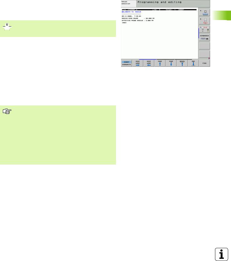
Recording measured values from the touch probe cycles
The TNC must be specially prepared by the machine tool builder for use of this function. The machine tool manual provides further information.
After executing any selected touch probe cycle, the TNC displays the PRINT soft key. If you press this soft key, the TNC will record the current values determined in the active touch probe cycle. You can then use the PRINT function in the menu for setting the data interface (see the User's Manual Chapter 12, “MOD Functions, Setting the Data Interfaces”) to define whether the TNC is to
print the measuring result,
store the measuring results on the TNC’s hard disk, or
store the measuring results on a PC.
If you store the measuring results, the TNC creates the ASCII file %TCHPRNT.A. Unless you define a specific path and interface in the interface configuration menu, the TNC will store the %TCHPRNT file in the main directory TNC:\.
When you press the PRINT soft key, the %TCHPRNT.A file must not be active in the Programming and Editing mode of operation. The TNC will otherwise display an error message.
The TNC stores the measured data in the %TCHPRNT.A file only. If you execute several touch probe cycles in succession and want to store the resulting measured data, you must make a backup of the contents stored in %TCHPRNT.A between the individual cycles by copying or renaming the file.
Format and contents of the %TCHPRNT file are preset by the machine tool builder.
2.1 Introduction
HEIDENHAIN iTNC 530 |
27 |
2.1 Introduction
Writing the measured values from touch probe cycles in datum tables
This function is active only if you have datum tables active on your TNC (bit 3 in Machine Parameter 7224.0 =0).
Use this function if you want to save measured values in the workpiece coordinate system. If you want to save measured values in the fixed machine coordinate system (REF coordinates), press the ENTER IN PRESET TABLE soft key (see “Writing the measured values from touch probe cycles in the preset table” on page 29).
With the ENTER IN DATUM TABLE soft key, the TNC can write the values measured during a touch probe cycle in a datum table:
Note that during an active datum shift the TNC always bases the probed value on the active preset (or on the datum most recently set in the Manual operating mode), although the datum shift is included in the position display.
8Select any probe function.
8Enter the desired coordinates of the datum in the appropriate input boxes (depends on the touch probe cycle being run).
8Enter the datum number in the Number in table= input box.
8Enter the name of the datum table (complete path) in the Datum table input box.
8Press the ENTER IN DATUM TABLE soft key. The TNC saves the datum in the indicated datum table under the entered number.
28 |
2 Touch Probe Cycles in the Manual and Electronic Handwheel Modes |
Writing the measured values from touch probe cycles in the preset table
Use this function if you want to save measured values in the fixed machine coordinate system (REF coordinates). If you want to save measured values in the workpiece coordinate system, press the ENTER IN DATUM TABLE soft key (see “Writing the measured values from touch probe cycles in datum tables” on page 28).
With the ENTER IN PRESET TABLE soft key, the TNC can write the values measured during a probe cycle in the preset table. The measured values are then stored referenced to the machine-based coordinate system (REF coordinates). The preset table has the name PRESET.PR, and is saved in the directory TNC:\.
Note that during an active datum shift the TNC always bases the probed value on the active preset (or on the datum most recently set in the Manual operating mode), although the datum shift is included in the position display.
8Select any probe function.
8Enter the desired coordinates of the datum in the appropriate input boxes (depends on the touch probe cycle being run).
8Enter the preset number in the Number in table: input box.
8Press the ENTER IN PRESET TABLE soft key. The TNC saves the datum in the preset table under the entered number.
If you overwrite the active datum, the TNC shows a warning. If you really want to overwrite it, press the ENT key. If not, press the NO ENT key.
2.1 Introduction
HEIDENHAIN iTNC 530 |
29 |
2.2 Calibrating a Touch Trigger Probe
2.2Calibrating a Touch Trigger Probe
Introduction
The touch probe must be calibrated in the following cases:
Commissioning
Stylus breakage
Stylus exchange
Change in the probe feed rate
Irregularities caused, for example, when the machine heats up
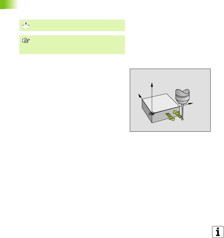
During calibration, the TNC finds the “effective” length of the stylus and the “effective” radius of the ball tip. To calibrate the touch probe, clamp a ring gauge of known height and known internal radius to the machine table.
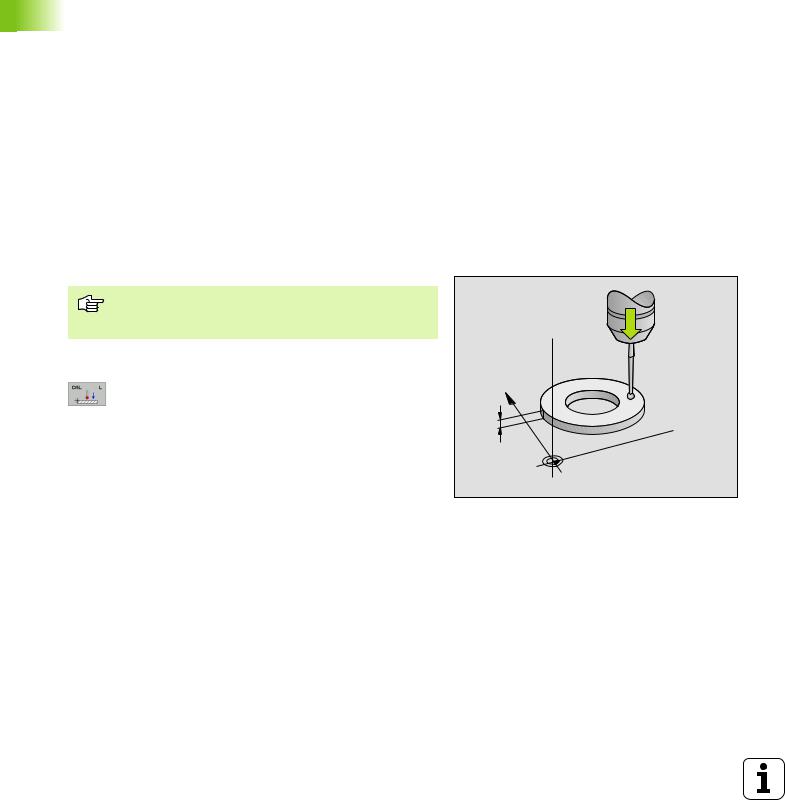
Calibrating the effective length
The effective length of the touch probe is always referenced to the tool datum. The machine tool builder usually defines the spindle tip as the tool datum.
8Set the datum in the spindle axis such that for the machine tool table Z=0.
8To select the calibration function for the touch probe length, press the TOUCH PROBE and CAL. L soft keys. The TNC then displays a menu window with four input boxes.
8Enter the tool axis (with the axis key).
8Datum: Enter the height of the ring gauge.
8The menu items Effective ball radius and Effective length do not require input.
8Move the touch probe to a position just above the ring gauge.
8To change the traverse direction (if necessary), press a soft key or an arrow key.
8To probe the upper surface of the ring gauge, press the machine START button.
Z 
Y
5
 X
X
30 |
2 Touch Probe Cycles in the Manual and Electronic Handwheel Modes |
Loading...