


iTNC 530
Table of contents
 Loading...
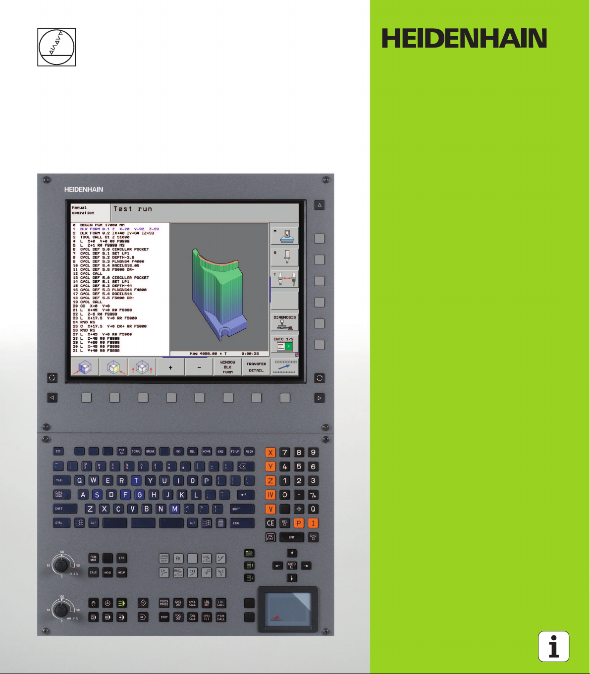
User’s Manual
HEIDENHAIN
Conversational
iTNC 530
NC Software
340 490-05
340 491-05
340 492-05
340 493-05
340 494-05
English (en)
12/2008
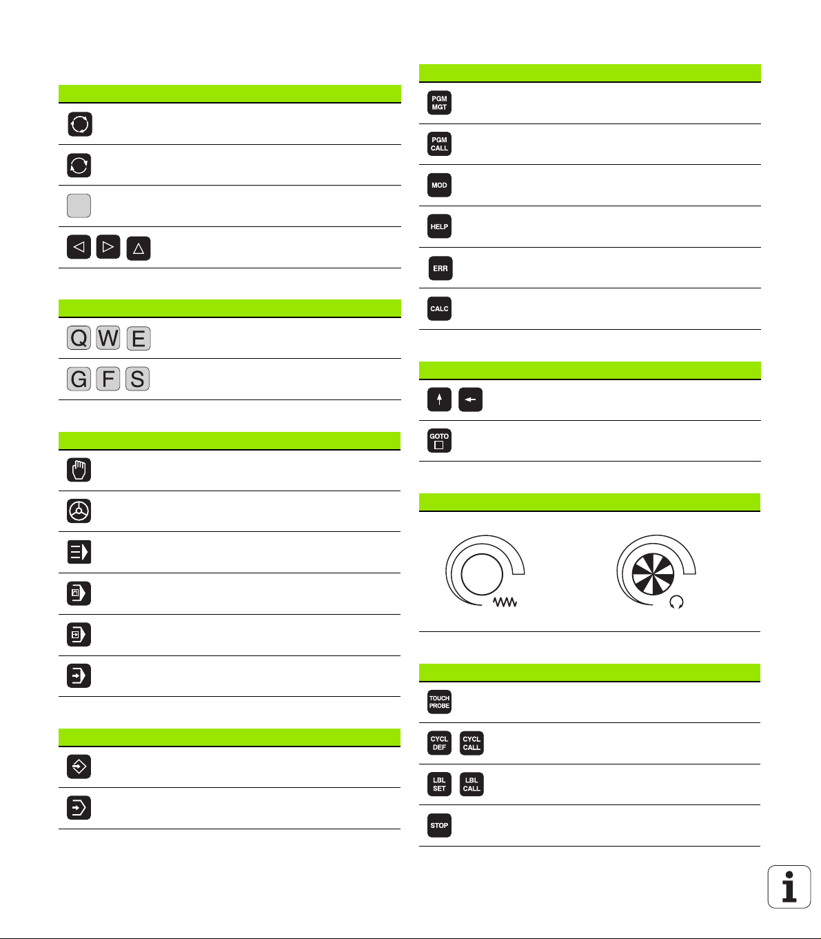
Controls of the TNC
Keys on visual display unit
Key Function
Split screen layout
Toggle display between machining and
programming modes
Soft keys for selecting functions on
screen
Shift between soft-key rows
Alphanumeric keyboard
Key Function
File names, comments
DIN/ISO programming
Machine operating modes
Key Function
Manual Operation
Electronic Handwheel
Program/file management, TNC functions
Key Function
Select or delete programs and files,
external data transfer
Define program call, select datum and
point tables
Select MOD functions
Display help text for NC error messages,
call TNCguide
Display all current error messages
Show pocket calculator
Navigation keys
Key Function
Move highlight
Go directly to blocks, cycles and
parameter functions
Potentiometer for feed rate and spindle speed
Feed rate Spindle speed
smarT.NC
Positioning with Manual Data Input
Program Run, Single Block
Program Run, Full Sequence
Programming modes
Key Function
Programming and Editing
Test Run
100
0
1
S %
50
50
100
0
1
F %
50
50
Cycles, subprograms and program section repeats
Key Function
Define touch probe cycles
Define and call cycles
Enter and call labels for subprogramming
and program section repeats
Program stop in a program
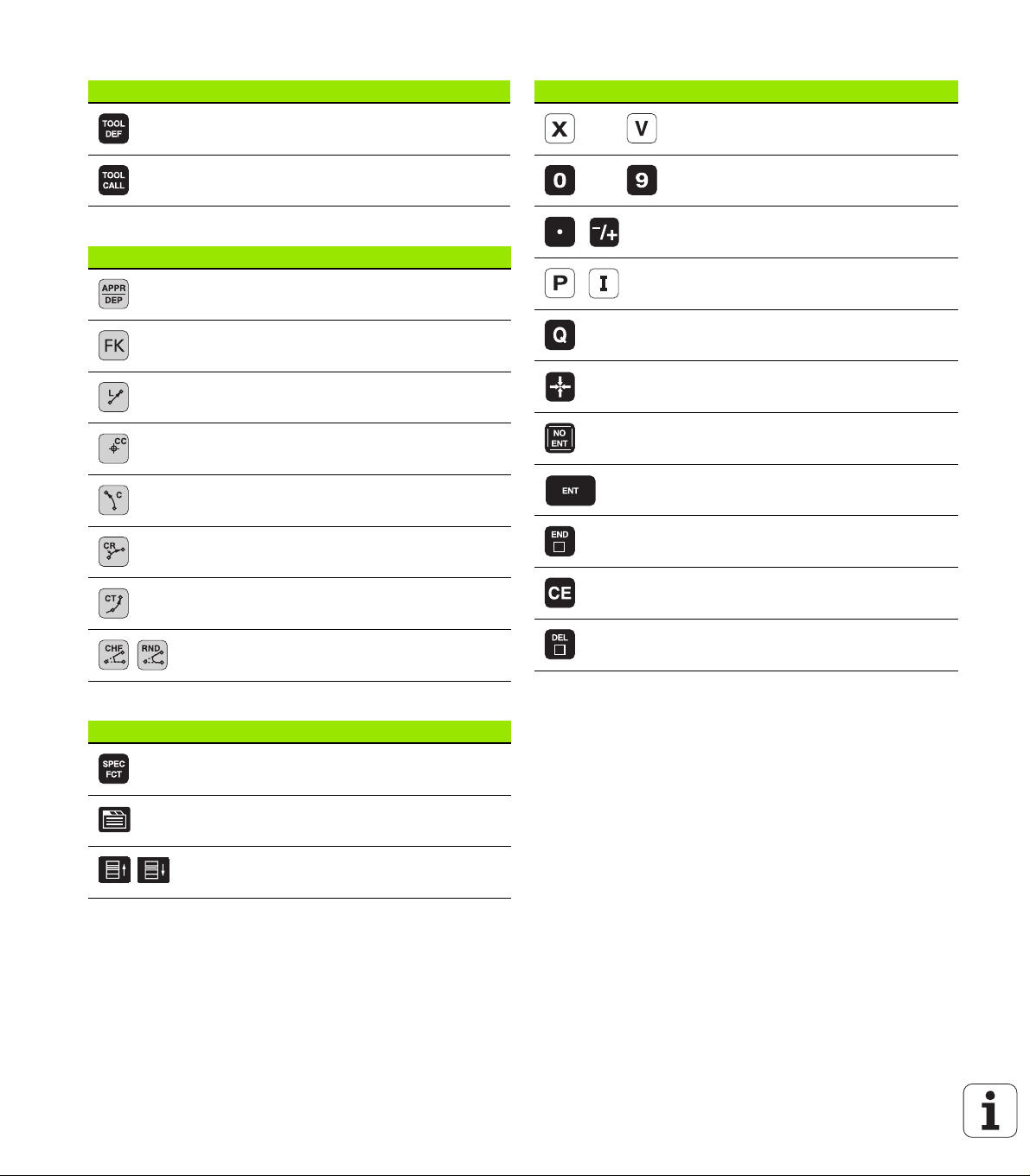
Tool functions
Key Function
Define tool data in the program
Coordinate axes and numbers: Entering and editing
Key Function
. . .
Select coordinate axes or
enter them into the program
Call tool data
Programming path movements
Key Function
Approach/depart contour
FK free contour programming
Straight line
Circle center/pole for polar coordinates
Circle with center
Circle with radius
Circular arc with tangential connection
Chamfering/Corner rounding
. . .
Numbers
Decimal point / Reverse algebraic sign
Polar coordinate input / Incremental
values
Q parameter programming /
Q parameter status
Save actual position or values from
calculator
Skip dialog questions, delete words
Confirm entry and resume dialog
Conclude block and exit entry
Clear numerical entry or TNC error
message
Abort dialog, delete program section
Special functions / smarT.NC
Key Function
Show special functions
smarT.NC: Select next tab on form
smarT.NC: Select first input field in
previous/next frame

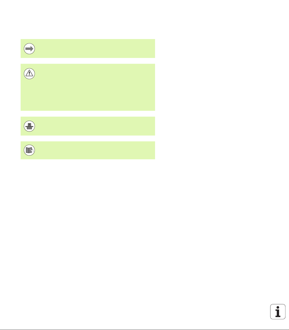
About this Manual
The symbols used in this manual are described below.
This symbol indicates that important notes about the
function described must be adhered to.
This symbol indicates that using the function described
runs one or more than one of the following risks:
Danger to workpiece
Danger to fixtures
Danger to tool
Danger to machine
Danger to operator
This symbol indicates that the described function must be
adapted by the machine tool builder. The function
described may therefore vary depending on the machine.
This symbol indicates that you can find detailed
information about a function in another manual.
About this Manual
Do you desire any changes, or have you found any errors?
We are continuously striving to improve documentation for you.
Please help us by sending your requests to the following e-mail
address: tnc-userdoc@heidenhain.de.
HEIDENHAIN iTNC 530 5

TNC Model, Software and Features
This manual describes functions and features provided by TNCs as of
the following NC software numbers.
TNC model NC software number
iTNC 530 340 490-05
iTNC 530 E 340 491-05
iTNC 530 340 492-05
iTNC 530 E 340 493-05
iTNC 530 programming station 340 494-05
The suffix E indicates the export version of the TNC. The export
version of the TNC has the following limitations:
Simultaneous linear movement in up to 4 axes
The machine tool builder adapts the usable features of the TNC to his
machine by setting machine parameters. Some of the functions
described in this manual may therefore not be among the features
provided by the TNC on your machine tool.
TNC Model, Software and Features
TNC functions that may not be available on your machine include:
Tool measurement with the TT
Please contact your machine tool builder to become familiar with the
features of your machine.
Many machine manufacturers, as well as HEIDENHAIN, offer
programming courses for the TNCs. We recommend these courses as
an effective way of improving your programming skill and sharing
information and ideas with other TNC users.
User’s Manual for Cycles:
All of the cycle functions (touch probe cycles and fixed
cycles) are described in a separate manual. Please contact
HEIDENHAIN if you require a copy of this User’s Manual.
ID: 670 388-xx
smarT.NC user documentation:
The smarT.NC operating mode is described in a separate
Pilot. Please contact HEIDENHAIN if you require a copy of
this Pilot. ID: 533 191-xx
6

Software options
The iTNC 530 features various software options that can be enabled
by you or your machine tool builder. Each option is to be enabled
separately and contains the following respective functions:
Software option 1
Cylinder surface interpolation (Cycles 27, 28, 29 and 39)
Feed rate in mm/min for rotary axes: M116
Tilting the machining plane (Cycle 19, PLANE function and 3-D ROT
soft key in the Manual Operation mode)
Circle in 3 axes with tilted working plane
Software option 2
Block processing time 0.5 ms instead of 3.6 ms
5-axis interpolation
Spline interpolation
3-D machining:
M114: Automatic compensation of machine geometry when
working with swivel axes
M128: Maintaining the position of the tool tip when positioning
with swivel axes (TCPM)
FUNCTION TCPM: Maintaining the position of the tool tip when
positioning with swivel axes (TCPM) in selectable modes
M144: Compensating the machine’s kinematics configuration for
ACTUAL/NOMINAL positions at end of block
Additional parameters for finishing/roughing and tolerance for
rotary axes in Cycle 32 (G62)
LN blocks (3-D compensation)
TNC Model, Software and Features
DCM Collision software option Description
Function that monitors areas defined by the
machine manufacturer to prevent collisions.
DXF Converter software option Description
Extract contours and machining positions from
DXF files (R12 format).
HEIDENHAIN iTNC 530 7
Page 365
Page 240

Additional dialog language software
option
Function for enabling the conversational
languages Slovenian, Slovak, Norwegian,
Latvian, Estonian, Korean, Turkish, Romanian,
Lithuanian
Global Program Settings software option Description
Function for superimposing coordinate
transformations in the Program Run modes,
handwheel superimposed traverse in virtual
axis direction.
AFC software option Description
Function for adaptive feed-rate control for
optimizing the machining conditions during
series production.
KinematicsOpt software option Description
Touch-probe cycles for inspecting and
optimizing the machine accuracy.
TNC Model, Software and Features
Description
Page 620
Page 380
Page 391
User’s Manual for
Cycles
8

Feature content level (upgrade functions)
Along with software options, significant further improvements of the
TNC software are managed via the Feature Content Level (FCL)
upgrade functions. Functions subject to the FCL are not available
simply by updating the software on your TNC.
All upgrade functions are available to you without surcharge
when you receive a new machine.
Upgrade functions are identified in the manual with FCL n, where n
indicates the sequential number of the feature content level.
You can purchase a code number in order to permanently enable the
FCL functions. For more information, contact your machine tool
builder or HEIDENHAIN.
FCL 4 functions Description
Graphical depiction of the protected
space when DCM collision monitoring is
active
Page 370
Handwheel superimposition in stopped
condition when DCM collision
monitoring is active
3-D basic rotation (set-up compensation) Machine Manual
FCL 3 functions Description
Touch probe cycle for 3-D probing User’s Manual for Cycles
Touch probe cycles for automatic datum
setting using the center of a slot/ridge
Feed-rate reduction for the machining of
contour pockets with the tool being in full
contact with the workpiece
PLANE function: Entry of axis angle Page 442
User documentation as a contextsensitive help system
smarT.NC: Programming of smarT.NC
and machining can be carried out
simultaneously
smarT.NC: Contour pocket on point
pattern
smarT.NC: Preview of contour programs
in the file manager
Page 369
User’s Manual for Cycles
User’s Manual for Cycles
Page 150
Page 118
smarT.NC Pilot
smarT.NC Pilot
TNC Model, Software and Features
smarT.NC: Positioning strategy for
machining point patterns
HEIDENHAIN iTNC 530 9
smarT.NC Pilot

FCL 2 functions Description
3-D line graphics Page 142
Virtual tool axis Page 541
USB support of block devices (memory
sticks, hard disks, CD-ROM drives)
Filtering of externally created contours Page 405
Possibility of assigning different depths
to each subcontour in the contour
formula
DHCP dynamic IP-address management Page 598
Touch-probe cycle for global setting of
touch-probe parameters
smarT.NC: Graphic support of block scan smarT.NC Pilot
smarT.NC: Coordinate transformation smarT.NC Pilot
smarT.NC: PLANE function smarT.NC Pilot
Intended place of operation
TNC Model, Software and Features
The TNC complies with the limits for a Class A device in accordance
with the specifications in EN 55022, and is intended for use primarily
in industrially-zoned areas.
Page 128
User’s Manual for
Cycles
User’s Manual for Touch
Probe Cycles
Legal information
This product uses open source software. Further information is
available on the control under
U Programming and Editing operating mode
U MOD function
U LEGAL INFORMATION soft key
10

New functions in 340 49x-01 since the predecessor versions 340 422-xx/340 423-xx
A new form-based operating mode, smarT.NC, has been
introduced. These cycles are described in a separate user's
document. In connection with this the TNC operating panel was
enhanced. There are some new keys available for quicker navigation
within smarT.NC
The single-processor version supports pointing devices (mice) via
the USB interface.
The tooth feed f
alternate feed entries (see “Possible feed rate input” on page 103).
New cycle CENTERING (see User’s Manual for Cycles)
New M function M150 for suppressing limit switch messages (see
“Suppress limit switch message: M150” on page 358)
M128 is now also permitted for mid-program startup (see “Mid-
program startup (block scan)” on page 572)
The number of available Q parameters was expanded to 2000 (see
“Principle and Overview” on page 274).
The number of available label numbers was expanded to 1000. Now
label names can be assigned as well (see “Labeling Subprograms
and Program Section Repeats” on page 258).
In the Q parameter functions FN9 to FN12 you can now also assign
label names as jump targets (see “If-Then Decisions with
Q Parameters” on page 284).
Selectively machine points from a point table (see User's Manual for
Cycles)
The current time is also shown in the additional status display
window (see “General program information (PGM tab)” on page
83).
Several columns were added to the tool table (see “Tool table:
Standard tool data” on page 162).
The Test Run can now also be stopped and resumed within
machining cycles (see “Running a program test” on page 563).
and feed per revolution fu can now be defined as
z
340 422-xx/340 423-xx
HEIDENHAIN iTNC 530 11
New functions in 340 49x-01 since the predecessor versions

New functions with 340 49x-02
DXF files can be opened directly on the TNC, in order to extract
contours into a plain-language program (see “Processing DXF Files
(Software Option)” on page 240)
3-D line graphics are now available in the Programming and Editing
operating mode (see “3-D Line Graphics (FCL2 Function)” on page
142)
The active tool-axis direction can now be set as the active machining
direction for manual operation (see “Setting the current tool-axis
direction as the active machining direction (FCL 2 function)” on page
541)
The machine manufacturer can now define any areas on the
machine for collision monitoring (see “Dynamic Collision Monitoring
(Software Option)” on page 365)
Instead of the spindle speed S you can now define the cutting speed
Vc in m/min (see “Calling tool data” on page 173)
The TNC can now display freely definable tables in the familiar table
view or as forms (see “Switching between table and form view” on
page 422)
The function for converting FK programs to H was expanded.
New functions with 340 49x-02
Programs can now also be output in linearized format (see
“Converting FK programs into HEIDENHAIN conversational format”
on page 224)
You can filter contours that were created using external
programming systems (see “Filtering Contours (FCL 2 Function)”
on page 405)
For contours which you connect via the contour formula, you can
now assign separate machining depths for each subcontour (see
User's Manual for Cycles)
The single-processor version now supports not only pointing
devices (mice), but also USB block devices (memory sticks, disk
drives, hard disks, CD-ROM drives) (see “USB devices on the TNC
(FCL 2 function)” on page 134)
12

New functions with 340 49x-03
The Adaptive Feed Control function (AFC) was introduced (see
“Adaptive Feed Control Software Option (AFC)” on page 391)
The global parameter settings function makes it possible to set
various transformations and settings in the program run modes (see
“Global Program Settings (Software Option)” on page 380).
The TNC now features a context-sensitive help system, the
TNCguide (see “The Context-Sensitive Help System TNCguide
(FCL3 Function)” on page 150).
Now you can extract point files from DXF files(see “Selecting and
storing machining positions” on page 250).
Now, in the DXF converter, you can divide or lengthen laterally
joined contour elements (see “Dividing, extending and shortening
contour elements” on page 249).
In the PLANE function the working plane can now also be defined
directly by its axis angle (see “Tilting the working plane through axis
angle: PLANE AXIAL (FCL 3 function)” on page 442).
In Cycle 22 ROUGH-OUT, you can define a feed-rate reduction if the
tool is cutting on its entire circumference (FCL3 function, see User's
Manual for Cycles)
In Cycle 208 BORE MILLING, you can now choose between climb or
up-cut milling (see User's Manual for Cycles)
String processing has been introduced in Q parameter programming
(see “String Parameters” on page 312)
A screen saver can be activated through machine parameter 7392
(see “General User Parameters” on page 620)
The TNC now also supports a network connection over the NFS V3
protocol (see “Ethernet Interface” on page 591)
The maximum manageable number of tools in a pocket table was
increased to 9999 (see “Pocket table for tool changer” on page 170)
Parallel programming is possible with smarT.NC (see “Select
smarT.NC programs” on page 118)
The system time can now be set through the MOD function (see
“Setting the System Time” on page 615)
New functions with 340 49x-03
HEIDENHAIN iTNC 530 13

New functions with 340 49x-04
The global parameter settings function makes it possible to activate
handwheel superimposed traverse in the active tool axis direction
(virtual axis) (see “Virtual axis VT” on page 390)
Machining patterns can now easily be defined with PATTERN DEF
(see User's Manual for Cycles)
Program defaults valid globally can now be defined for machining
cycles (see User's Manual for Cycles)
Now, in Cycle 209 TAPPING WITH CHIP BREAKING, you can define a
factor for the retraction shaft speed, so that you can depart the hole
faster (see User's Manual for Cycles)
In Cycle 22 ROUGH-OUT, you can now define the fine-roughing
strategy (see User's Manual for Cycles)
In the new Cycle 270 CONTOUR TRAIN DATA, you can define the type
of approach of Cycle 25 CONTOUR TRAIN (see User's Manual for
Cycles)
New Q-parameter function for reading a system datum was
introduced (see “Copying system data to a string parameter,” page
317)
New functions with 340 49x-04
New functions for copying, moving and deleting files from within
the NC program were introduced (see “File Functions,” page 406)
DCM: Collision objects can now be shown three-dimensionally
during machining (see “Graphic depiction of the protected space
(FCL4 function),” page 370)
DXF converter: New settings possibility introduced, with which the
TNC automatically selects the circle center when loading points
from circular elements (see “Basic settings,” page 242)
DXF converter: Element information is shown in an additional info
window (see “Selecting and saving a contour,” page 247)
AFC: A line diagram is now shown in the additional AFC status
display (see “Adaptive Feed Control (AFC tab, software option)” on
page 89)
AFC: Control settings parameters selectable by machine tool builder
(see “Adaptive Feed Control Software Option (AFC)” on page 391)
AFC: The spindle reference load currently being taught is shown in
a pop-up window in the teach-in mode. In addition, the learning
phase can be restarted at any time via soft key (see “Recording a
teach-in cut” on page 395).
AFC: The dependent file <name>.H.AFC.DEP can now also be
modified in the Programming and Editing operating mode (see
“Recording a teach-in cut” on page 395)
14

The maximum path permitted for LIFTOFF was increased to 30 mm
(see “Automatically retract tool from the contour at an NC stop:
M148” on page 357)
File management was adapted to the file management of smarT.NC
(see “Overview: Functions of the file manager” on page 114)
New function for generating service files was introduced (see
“Generating service files” on page 149)
A window manager was introduced (see “Window Manager” on
page 90)
The new dialog languages Turkish and Romanian were introduced
(software option, Page 620)
New functions with 340 49x-04
HEIDENHAIN iTNC 530 15

New functions with 340 49x-05
DCM: Integrated fixture management (see “Fixture Monitoring
(Software Option)” on page 372)
DCM: No collision checking in the Test Run mode(see “Collision
monitoring in the Test Run mode of operation” on page 371)
DCM: Management of tool-carrier kinematics has been simplified
(see “Tool-carrier kinematics” on page 168)
Processing DXF data: Fast point selection via mouse area (see
“Quick selection of hole positions in an area defined by the mouse”
on page 252)
Processing DXF data: Fast point selection via diameter input (see
“Quick selection of hole positions in an area defined by the mouse”
on page 252)
DXF data processing: Polyline support was integrated (see
“Processing DXF Files (Software Option)” on page 240)
AFC: Smallest occurring feed rate will now also be saved in the log
file (see “Log file” on page 399)
AFC: Monitoring for tool breakage/tool wear (see “Tool
breakage/tool wear monitoring” on page 401)
New functions with 340 49x-05
AFC: Direct monitoring of spindle load (see “Spindle load
monitoring” on page 401)
Global program settings: Function also partially effective with
M91/M92 blocks (see “Global Program Settings (Software Option)”
on page 380)
Pallet preset table added (see “Pallet datum management with the
pallet preset table,” page 477 or see “Application,” page 474 or see
“Storing measured values in the pallet preset table,” page 521 or
see “Saving the basic rotation in the preset table,” page 526)
The additional status display now has an additional tab, i.e. PAL, on
which an active pallet preset is displayed (see “General pallet
information (PAL tab)” on page 84)
New tool management (see “Tool management” on page 179)
New column R2TOL in the tool table (see “Tool table: Tool data
required for automatic tool measurement” on page 164)
Tools can now also be selected during tool call by soft key directly
from TOOL.T (see “Calling tool data” on page 173)
TNCguide: Context sensitivity has been improved in that when the
cursor is engaged it jumps to the appropriate description (see
“Calling the TNCguide” on page 151)
Lithuanian dialog added, machine parameter 7230 (see “List of
general user parameters” on page 621)
M116 allowed in combination with M128 (see “Feed rate in
mm/min on rotary axes A, B, C: M116 (software option 1)” on page
455)
Introduction of local and nonvolatile Q parameters QL and QR (see
“Principle and Overview” on page 274)
The MOD function can now test the data medium (see “Checking
the Data Carrier” on page 614)
New Cycle 241 for Single-Fluted Deep-Hole Drilling (see User’s
Manual for Cycles)
16

Touch probe cycle 404 (SET BASIC ROTATION) was expanded by
parameter Q305 (Number in table) in order to write basic rotations
to the preset table (see User's Manual for Cycles)
Touch probe cycles 408 to 419: The TNC now also writes to line 0
of the preset table when the display value is set (see User's Manual
for Cycles)
Touch probe cycle 416 (Datum on Circle Center) was expanded by
parameter Q320 (safety clearance) (see User's Manual for Cycles)
Touch probe cycles 412, 413, 421 and 422: Additional parameter
Q365 (type of traverse) (see User's Manual for Cycles)
Touch probe cycle 425 (Measure Slot) was expanded by parameters
Q301 (Move to clearance height) and Q320 (setup clearance) (see
User's Manual for Cycles)
Touch probe cycle 450 (Save Kinematics) was expanded by input
option 2 (Display saving status) in parameter Q410 (mode) (see
User's Manual for Cycles)
Touch probe cycle 451 (Measure Kinematics) was expanded by
parameters Q423 (number of circular measurements) and Q432 (set
preset) (see User's Manual for Cycles)
New touch probe cycle 452 (Preset Compensation) simplifies the
measurement of tool changer heads (see User's Manual for Cycles)
New touch probe cycle 484 for calibrating the wireless TT 449 tool
touch probe (see User's Manual for Cycles)
New functions with 340 49x-05
HEIDENHAIN iTNC 530 17

Changed functions in 340 49x-01 since the predecessor versions 340 422-xx/340 423-xx
The layouts of the status display and additional status display were
redesigned (see “Status Displays” on page 81)
Software 340 490 no longer supports the small resolution in
combination with the BC 120 screen (see “Visual display unit” on
page 75)
New key layout of the TE 530 B keyboard unit (see “Operating
panel” on page 77)
The entry range for the EULPR precession angle in the PLANE EULER
function was expanded (see “Defining the machining plane with
340 422-xx/340 423-xx
Euler angles: EULER PLANE” on page 435)
The plane vector in the VECTOR PLANE function no longer has to be
entered in standardized form (see “Defining the machining plane
with two vectors: VECTOR PLANE” on page 437)
Positioning behavior of the CYCL CALL PAT function has been
modified (see User's Manual for Cycles)
The tool types available for selection in the tool table were increased
in preparation for future functions
Instead of the last 10, you can now choose from the last 15 selected
files (see “Choosing one of the last files selected” on page 123)
Changed functions in 340 49x-01 since the predecessor versions
18

Functions changed in 340 49x-02
Access to the preset table was simplified. There are also new
possibilities for entering values in the preset table. See table
“Manually saving the datums in the preset table”
In inch-programs, the function M136 (feed rate in 0.1 inch/rev) can
no longer be combined with the FU function
The feed-rate potentiometers of the HR 420 are no longer switched
over automatically when the handwheel is selected. The selection is
made via soft key on the handwheel. In addition, the pop-up window
for the active handwheel was made smaller, in order to improve the
view of the display beneath it (see “Potentiometer settings” on
page 503)
The maximum number of contour elements for SL cycles was
increased to 8192, so that much more complex contours can be
machined (see User's Manual for Cycles)
FN16: F-PRINT: The maximum number of Q-parameter values that
can be output per line in the format description file was increased to
32 (see “FN 16: F-PRINT: Formatted output of text and Q parameter
values” on page 294)
The soft keys START and START SINGLE BLOCK in the Program
Test mode of operation were switched, so that the soft-key
alignment is the same in all modes of operation (Programming and
Editing, smarT.NC, Test) (see “Running a program test” on page
563)
The design of the soft keys was revised completely
Functions changed in 340 49x-02
HEIDENHAIN iTNC 530 19

Changed functions with 340 49x-03
In Cycle 22 you can now define a tool name also for the coarse
roughing tool (see User's Manual Cycles)
In the PLANE function, an FMAX can now be programmed for the
automatic rotary positioning (see “Automatic positioning:
MOVE/TURN/STAY (entry is mandatory)” on page 444)
When running programs in which non-controlled axes are
programmed, the TNC now interrupts the program run and displays
a menu for returning to the programmed position (see
“Programming of noncontrolled axes (counter axes)” on page 569)
The tool usage file now also includes the total machining time,
which serves as the basis for the progress display in percent in the
Program Run, Full Sequence mode (see “Tool usage test” on page
576)
The TNC now also takes the dwell time into account when
calculating the machining time in the Test Run mode (see
“Measuring the machining time” on page 559)
Arcs that are not programmed in the active working plane can now
also be run as spatial arcs (see “Circular path C around circle center
CC” on page 205)
The EDIT OFF/ON soft key on the pocket table can be deactivated
by the machine tool builder (see “Pocket table for tool changer” on
page 170)
Changed functions with 340 49x-03
The additional status display has been revised. The following
improvements have been introduced (see “Additional status
displays” on page 82):
A new overview page with the most important status displays
were introduced
The individual status pages are now displayed as tabs (as in
smarT.NC). The individual tabs can be selected with the Page soft
keys or with the mouse
The current run time of the program is shown in percent by a
progress bar
The tolerance values set in Cycle 32 are displayed
Active global program settings are displayed, provided that this
software option was enabled
The status of the Adaptive Feed Control (AFC) is displayed,
provided that this software option was enabled
20

Changed functions with 340 49x-04
DCM: Retraction after collision simplified (see “Collision monitoring
in the manual operating modes,” page 367)
The input range for polar angles was increased (see “Circular path
CP around pole CC” on page 215)
The value range for Q-parameter assignment was increased (see
“Programming notes,” page 276)
The pocket-, stud- and slot-milling cycles 210 to 214 were removed
from the standard soft-key row (CYCL DEF >
POCKETS/STUDS/SLOTS). For reasons of compatibility, the cycles
will still be available, and can be selected via the GOTO key
The soft-key rows in the Test Run operating mode were modified to
those of the smarT.NC operating mode
Windows XP is now used on the dual-processor version (see
“Introduction” on page 648)
Conversion from FK to H was moved to the special functions (SPEC
FCT) (see “Converting FK programs into HEIDENHAIN
conversational format” on page 224)
Filtering of contours was moved to the special functions (SPEC FCT)
(see “Filtering Contours (FCL 2 Function)” on page 405)
Loading of values from the pocket calculator was changed (see “To
transfer the calculated value into the program” on page 139)
Changed functions with 340 49x-04
HEIDENHAIN iTNC 530 21

Changed functions with 340 49x-05
GS global program settings: Form was redesigned (see “Global
Program Settings (Software Option),” page 380)
The menu for network configuration was revised (see “Configuring
the TNC” on page 594)
Changed functions with 340 49x-05
22

Table of Contents
First Steps with the iTNC 530
1
Introduction
Programming: Fundamentals, File
Management
Programming: Programming Aids
Programming: Tools
Programming: Programming Contours
Programming: Miscellaneous Functions
Programming: Data Transfer from DXF
Files
Programming: Subprograms and
Program Section Repeats
Programming: Q Parameters
Programming: Miscellaneous Functions
Programming: Special Functions
Programming: Multi-axis Machining
2
3
4
5
6
7
8
9
10
11
12
13
Programming: Pallet Management
Positioning with Manual Data Input
Test Run and Program Run
MOD Functions
Tables and Overviews
iTNC 530 with Windows XP (option)
HEIDENHAIN iTNC 530 23
14
15
16
17
18
19


1 First Steps with the iTNC 530 ..... 51
1.1 Overview ..... 52
1.2 Machine Switch-On ..... 53
Acknowledge the power interruption and move to the reference points ..... 53
1.3 Programming the First Part ..... 54
Select the correct operating mode ..... 54
The most important TNC keys ..... 54
Create a new program/file management ..... 55
Define a workpiece blank ..... 56
Program layout ..... 57
Program a simple contour ..... 58
Create a cycle program ..... 61
1.4 Graphically Testing the Program ..... 64
Select the correct operating mode ..... 64
Select the tool table for the test run ..... 64
Choose the program you want to test ..... 65
Select the screen layout and the view ..... 65
Start the program test ..... 66
1.5 Setting Up Tools ..... 67
Select the correct operating mode ..... 67
Prepare and measure tools ..... 67
The tool table TOOL.T ..... 67
The pocket table TOOL_P.TCH ..... 68
1.6 Workpiece Setup ..... 69
Select the correct operating mode ..... 69
Clamp the workpiece ..... 69
Align the workpiece with a 3-D touch probe system ..... 70
Set the datum with a 3-D touch probe ..... 71
1.7 Running the First Program ..... 72
Select the correct operating mode ..... 72
Choose the program you want to run ..... 72
Start the program ..... 72
HEIDENHAIN iTNC 530 25

2 Introduction ..... 73
2.1 The iTNC 530 ..... 74
Programming: HEIDENHAIN conversational, smarT.NC and DIN/ISO formats ..... 74
Compatibility ..... 74
2.2 Visual Display Unit and Keyboard ..... 75
Visual display unit ..... 75
Sets the screen layout ..... 76
Operating panel ..... 77
2.3 Operating Modes ..... 78
Manual Operation and Electronic Handwheel ..... 78
Positioning with Manual Data Input ..... 78
Programming and Editing ..... 79
Test Run ..... 79
Program Run, Full Sequence and Program Run, Single Block ..... 80
2.4 Status Displays ..... 81
“General” status display ..... 81
Additional status displays ..... 82
2.5 Window Manager ..... 90
2.6 Accessories: HEIDENHAIN 3-D Touch Probes and Electronic Handwheels ..... 91
3-D touch probes ..... 91
HR electronic handwheels ..... 92
26

3 Programming: Fundamentals, File Management ..... 93
3.1 Fundamentals ..... 94
Position encoders and reference marks ..... 94
Reference system ..... 94
Reference system on milling machines ..... 95
Polar coordinates ..... 96
Absolute and incremental workpiece positions ..... 97
Setting the datum ..... 98
3.2 Creating and Writing Programs ..... 99
Organization of an NC program in HEIDENHAIN Conversational ..... 99
Define the blank: BLK FORM ..... 99
Creating a new part program ..... 100
Programming tool movements in conversational format ..... 102
Actual position capture ..... 104
Editing a program ..... 105
The TNC search function ..... 109
3.3 File Management: Fundamentals ..... 111
Files ..... 111
Data backup ..... 112
3.4 Working with the File Manager ..... 113
Directories ..... 113
Paths ..... 113
Overview: Functions of the file manager ..... 114
Calling the file manager ..... 115
Selecting drives, directories and files ..... 116
Creating a new directory (only possible on the drive TNC:\) ..... 119
Creating a new file (only possible on the drive TNC:\) ..... 119
Copying a single file ..... 120
Copying files into another directory ..... 121
Copying a table ..... 122
Copying a directory ..... 123
Choosing one of the last files selected ..... 123
Deleting a file ..... 124
Deleting a directory ..... 124
Tagging files ..... 125
Renaming a file ..... 127
Additional functions ..... 128
Working with shortcuts ..... 130
Data transfer to or from an external data medium ..... 131
The TNC in a network ..... 133
USB devices on the TNC (FCL 2 function) ..... 134
HEIDENHAIN iTNC 530 27

4 Programming: Programming Aids ..... 135
4.1 Adding Comments ..... 136
Function ..... 136
Entering comments during programming ..... 136
Inserting comments after program entry ..... 136
Entering a comment in a separate block ..... 136
Functions for editing of the comment ..... 137
4.2 Structuring Programs ..... 138
Definition and applications ..... 138
Displaying the program structure window / Changing the active window ..... 138
Inserting a structuring block in the (left) program window ..... 138
Selecting blocks in the program structure window ..... 138
4.3 Integrated Pocket Calculator ..... 139
Operation ..... 139
4.4 Programming Graphics ..... 140
Generating / Not generating graphics during programming: ..... 140
Generating a graphic for an existing program ..... 140
Block number display ON/OFF ..... 141
Erasing the graphic ..... 141
Magnifying or reducing a detail ..... 141
4.5 3-D Line Graphics (FCL2 Function) ..... 142
Function ..... 142
Functions of the 3-D line graphics ..... 142
Highlighting NC blocks in the graphics ..... 144
Block number display ON/OFF ..... 144
Erasing the graphic ..... 144
4.6 Immediate Help for NC Error Messages ..... 145
Displaying error messages ..... 145
Display HELP ..... 145
4.7 List of All Current Error Messages ..... 146
Function ..... 146
Show error list ..... 146
Window contents ..... 147
Calling the TNCguide help system ..... 148
Generating service files ..... 149
4.8 The Context-Sensitive Help System TNCguide (FCL3 Function) ..... 150
Function ..... 150
Working with the TNCguide ..... 151
Downloading current help files ..... 155
28

5 Programming: Tools ..... 157
5.1 Entering Tool-Related Data ..... 158
Feed rate F ..... 158
Spindle speed S ..... 159
5.2 Tool Data ..... 160
Requirements for tool compensation ..... 160
Tool numbers and tool names ..... 160
Tool length L ..... 160
Tool radius R ..... 160
Delta values for lengths and radii ..... 161
Entering tool data into the program ..... 161
Entering tool data in the table ..... 162
Tool-carrier kinematics ..... 168
Using an external PC to overwrite individual tool data ..... 169
Pocket table for tool changer ..... 170
Calling tool data ..... 173
Tool change ..... 175
Tool usage test ..... 177
Tool management ..... 179
5.3 Tool Compensation ..... 182
Introduction ..... 182
Tool length compensation ..... 182
Tool radius compensation ..... 183
HEIDENHAIN iTNC 530 29

6 Programming: Programming Contours ..... 187
6.1 Tool Movements ..... 188
Path functions ..... 188
FK free contour programming ..... 188
Miscellaneous functions M ..... 188
Subprograms and program section repeats ..... 188
Programming with Q parameters ..... 188
6.2 Fundamentals of Path Functions ..... 189
Programming tool movements for workpiece machining ..... 189
6.3 Contour Approach and Departure ..... 192
Overview: Types of paths for contour approach and departure ..... 192
Important positions for approach and departure ..... 193
Approaching on a straight line with tangential connection: APPR LT ..... 195
Approaching on a straight line perpendicular to the first contour point: APPR LN ..... 195
Approaching on a circular path with tangential connection: APPR CT ..... 196
Approaching on a circular arc with tangential connection from a straight line to the contour: APPR LCT ..... 197
Departing on a straight line with tangential connection: DEP LT ..... 198
Departing on a straight line perpendicular to the last contour point: DEP LN ..... 198
Departure on a circular path with tangential connection: DEP CT ..... 199
Departing on a circular arc tangentially connecting the contour and a straight line: DEP LCT ..... 199
6.4 Path Contours—Cartesian Coordinates ..... 200
Overview of path functions ..... 200
Straight line L ..... 201
Inserting a chamfer between two straight lines ..... 202
Corner rounding RND ..... 203
Circle center CCI ..... 204
Circular path C around circle center CC ..... 205
Circular path CR with defined radius ..... 206
Circular path CT with tangential connection ..... 208
6.5 Path Contours—Polar Coordinates ..... 213
Overview ..... 213
Zero point for polar coordinates: pole CC ..... 214
Straight line LP ..... 214
Circular path CP around pole CC ..... 215
Circular path CTP with tangential connection ..... 216
Helical interpolation ..... 217
30
Loading...