


iTNC 530
Table of contents
 Loading...
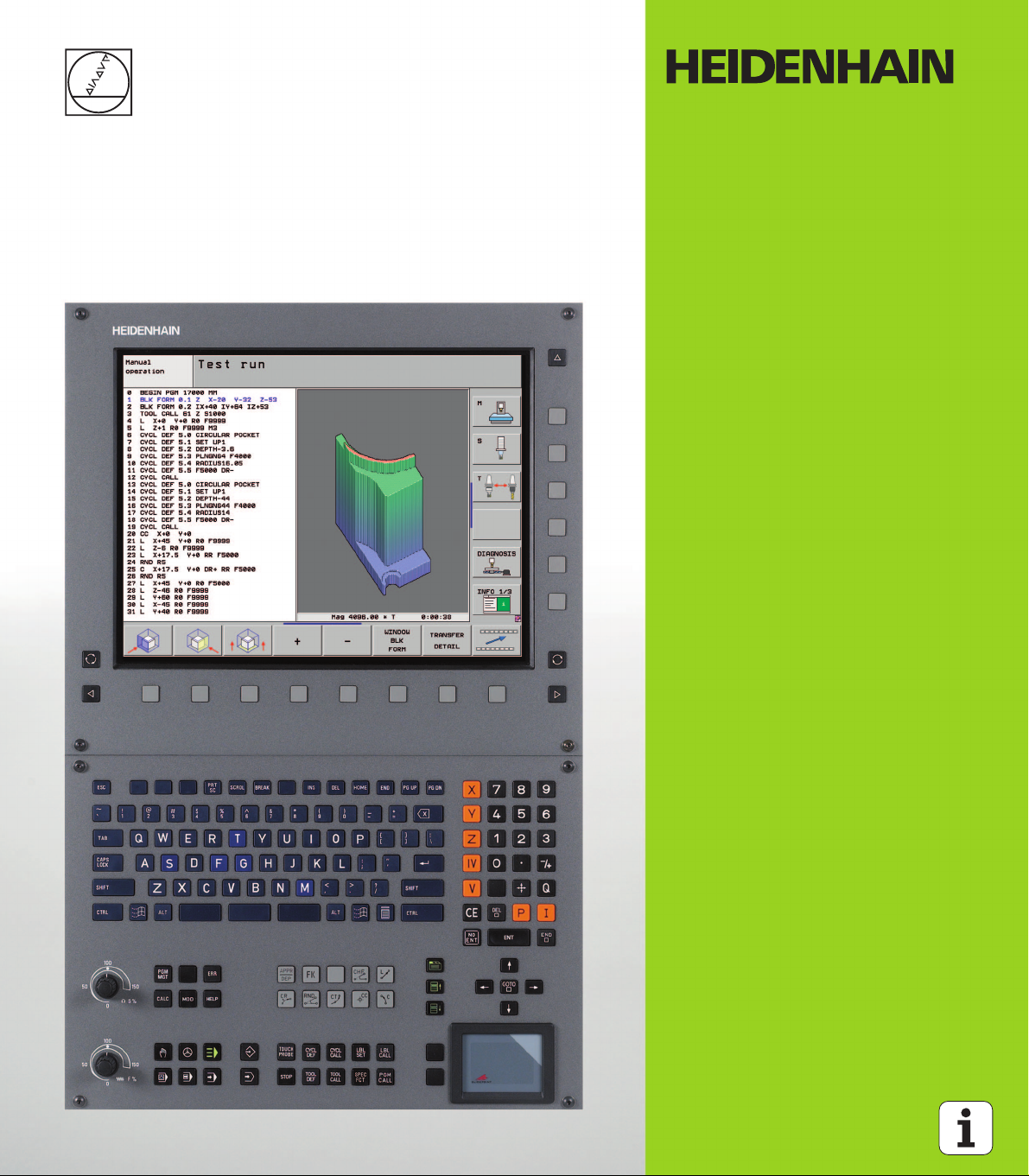
User’s Manual
DIN/ISO
Programming
iTNC 530
NC Software
340 490-06
340 491-06
340 492-06
340 493-06
340 494-06
English (en)
6/2010
Controls of the TNC
1
50
0
50
100
F %
1
50
0
50
100
S %
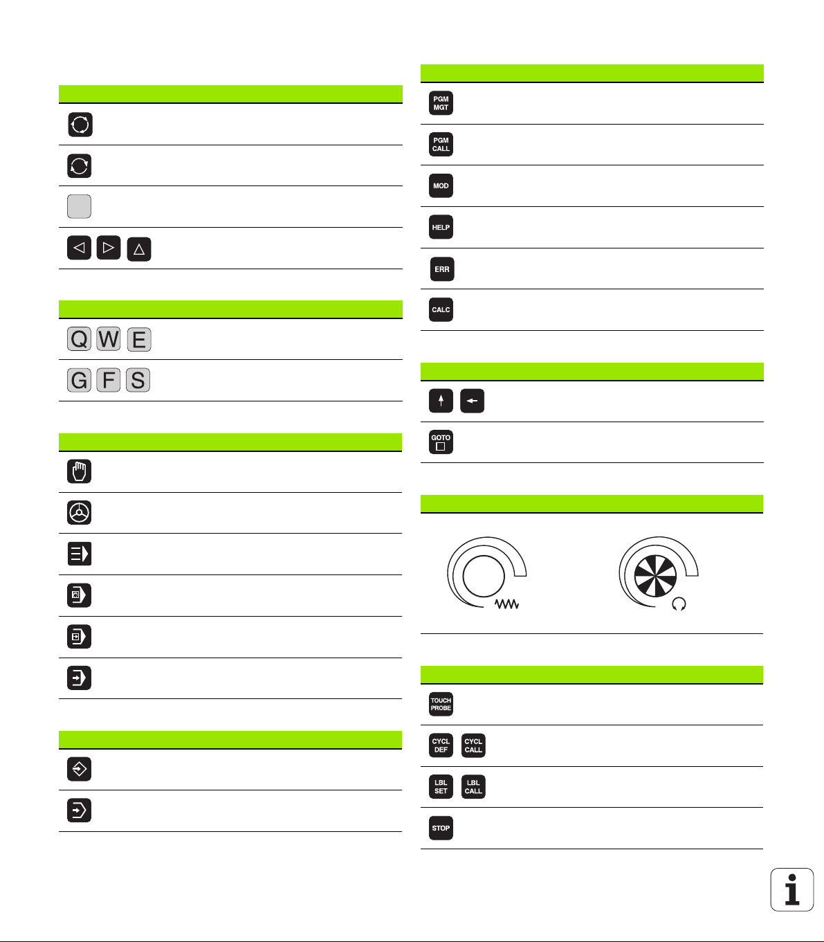
Keys on visual display unit
Key Function
Split screen layout
Toggle the display between machining
and programming modes
Soft keys for selecting functions on
screen
Shifts between soft-key rows
Alphanumeric keyboard
Key Function
File names, comments
DIN/ISO programming
Machine operating modes
Key Function
Manual Operation
Electronic Handwheel
Program/file management, TNC functions
Key Function
Select or delete programs and files,
external data transfer
Define program call, select datum and
point tables
Select MOD functions
Display help text for NC error messages,
call TNCguide
Display all current error messages
Show calculator
Navigation keys
Key Function
Move highlight
Go directly to blocks, cycles and
parameter functions
Potentiometer for feed rate and spindle speed
Feed rate Spindle speed
Programming modes
Key Function
smarT.NC
Positioning with Manual Data Input
Program Run, Single Block
Program Run, Full Sequence
Programming and Editing
Test Run
Cycles, subprograms and program section repeats
Key Function
Define touch probe cycles
Define and call cycles
Enter and call labels for subprogramming
and program section repeats
Program stop in a program
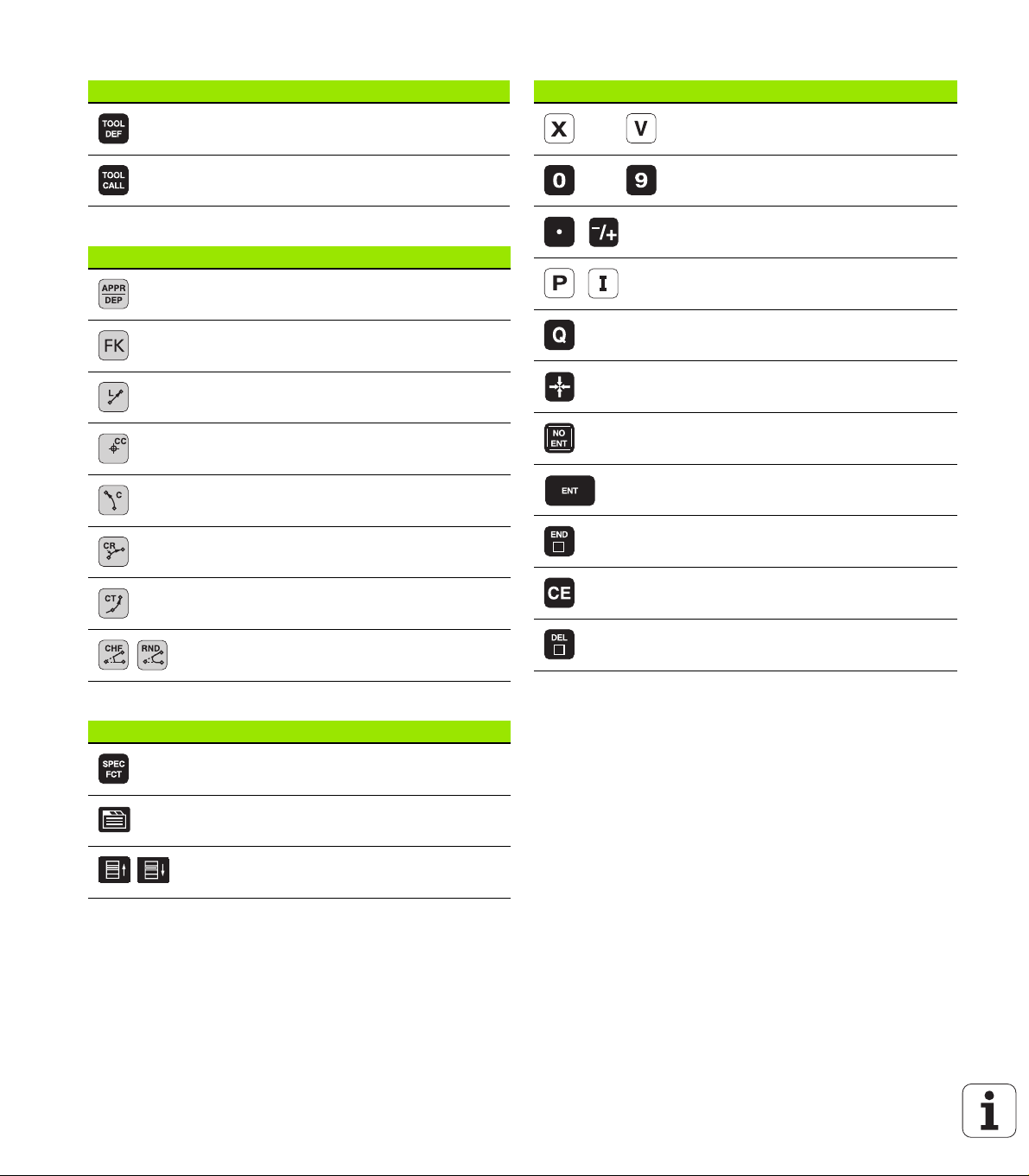
Tool functions
Key Function
Define tool data in the program
Coordinate axes and numbers: Entering and editing
Key Function
Select coordinate axes or
enter them into the program
Call tool data
Programming path movements
Key Function
Approach/depart contour
FK free contour programming
Straight line
Circle center/pole for polar coordinates
Circle with center
Circle with radius
Circular arc with tangential connection
Chamfering/corner rounding
Numbers
Decimal point / Reverse algebraic sign
Polar coordinate input / Incremental
values
Q parameter programming /
Q parameter status
Save actual position or values from
calculator
Skip dialog questions, delete words
Confirm entry and resume dialog
Conclude block and exit entry
Clear numerical entry or TNC error
message
Abort dialog, delete program section
Special functions / smarT.NC
Key Function
Show special functions
smarT.NC: Select next tab on form
smarT.NC: Select first input field in
previous/next frame

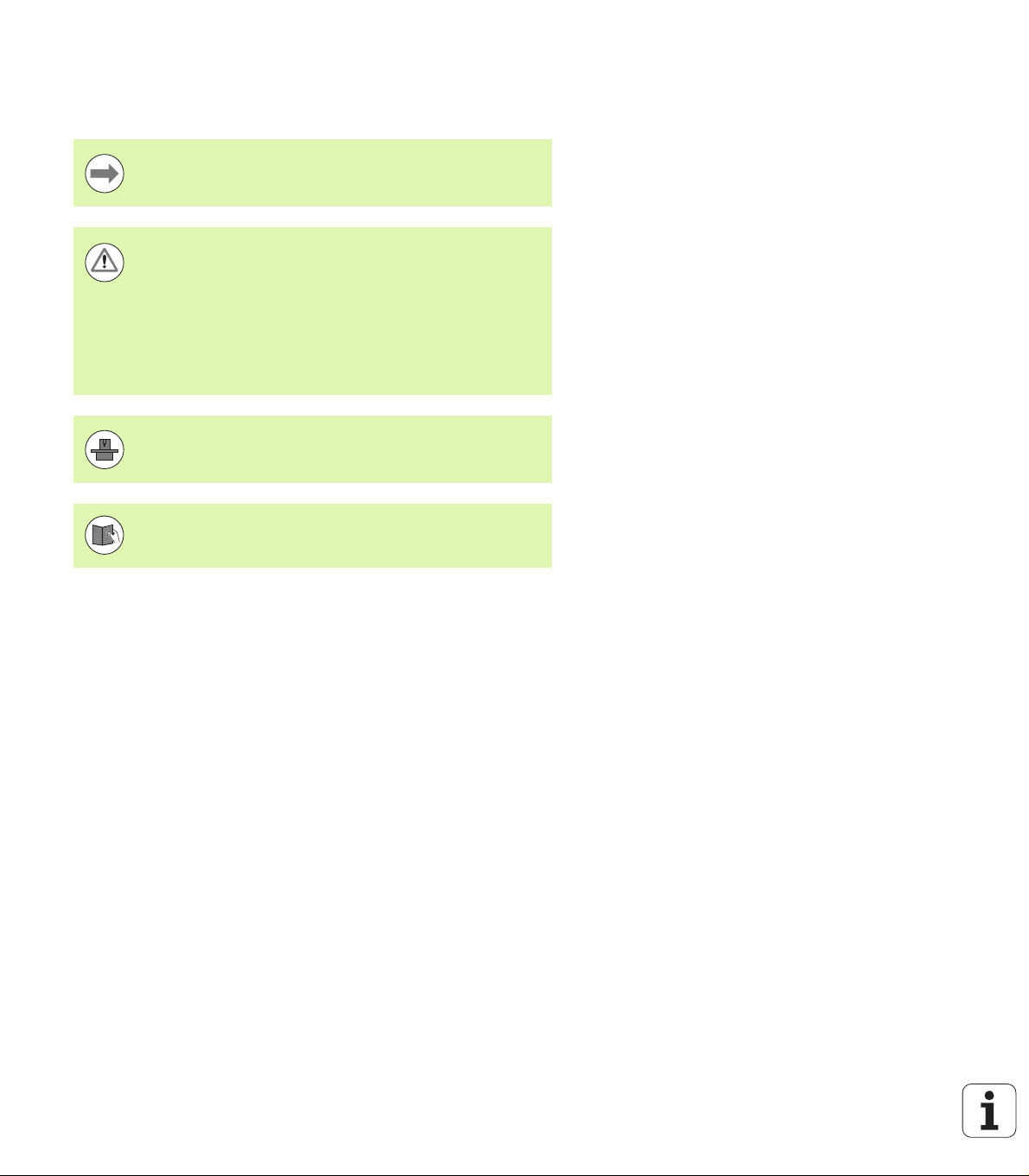
About this Manual
The symbols used in this manual are described below.
This symbol indicates that important notes about the
function described must be adhered to.
This symbol indicates that there is one or more of the
following risks when using the described function:
Danger to workpiece
Danger to fixtures
Danger to tool
Danger to machine
Danger to operator
This symbol indicates that the described function must be
adapted by the machine tool builder. The function
described may therefore vary depending on the machine.
This symbol indicates that you can find detailed
information about a function in another manual.
About this Manual
Would you like any changes, or have you found any errors?
We are continuously striving to improve documentation for you.
Please help us by sending your requests to the following e-mail
address: tnc-userdoc@heidenhain.de.
HEIDENHAIN iTNC 530 5

TNC Model, Software and Features
This manual describes functions and features provided by TNCs as of
the following NC software numbers.
TNC model NC software number
iTNC 530 340 490-06
iTNC 530 E 340 491-06
iTNC 530 340 492-06
iTNC 530 E 340 493-06
iTNC 530 programming station 340 494-06
The suffix E indicates the export version of the TNC. The export
version of the TNC has the following limitations:
Simultaneous linear movement in up to 4 axes
The machine tool builder adapts the usable features of the TNC to his
machine by setting machine parameters. Some of the functions
described in this manual may therefore not be among the features
provided by the TNC on your machine tool.
TNC Model, Software and Features
TNC functions that may not be available on your machine include:
Tool measurement with the TT
Please contact your machine tool builder to become familiar with the
features of your machine.
6

Many machine manufacturers, as well as HEIDENHAIN, offer
programming courses for the TNCs. We recommend these courses as
an effective way of improving your programming skill and sharing
information and ideas with other TNC users.
User’s Manual for Cycle Programming:
All of the cycle functions (touch probe cycles and fixed
cycles) are described in a separate manual. Please contact
HEIDENHAIN if you require a copy of this User’s Manual.
ID: 670 388-xx
smarT.NC user documentation:
The smarT.NC operating mode is described in a separate
Pilot. Please contact HEIDENHAIN if you require a copy of
this Pilot. ID: 533 191-xx.
TNC Model, Software and Features
HEIDENHAIN iTNC 530 7

Software options
The iTNC 530 features various software options that can be enabled
by you or your machine tool builder. Each option is to be enabled
separately and contains the following respective functions:
Software option 1
Cylinder surface interpolation (Cycles 27, 28, 29 and 39)
Feed rate in mm/min for rotary axes: M116
Tilting the machining plane (Cycle 19, PLANE function and 3-D ROT
soft key in the Manual operating mode)
Circle in 3 axes with tilted working plane
Software option 2
Block processing time 0.5 ms instead of 3.6 ms
5-axis interpolation
Spline interpolation
3-D machining:
M114: Automatic compensation of machine geometry when
TNC Model, Software and Features
working with swivel axes
M128: Maintaining the position of the tool tip when positioning
with tilted axes (TCPM)
FUNCTION TCPM: Maintaining the position of the tool tip when
positioning with tilted axes (TCPM) in selectable modes
M144: Compensating the machine’s kinematic configuration for
ACTUAL/NOMINAL positions at end of block
Additional parameters for finishing/roughing and tolerance
for rotary axes in Cycle 32 (G62)
LN blocks (3-D compensation)
DCM Collision software option Description
Function that monitors areas defined by the
machine manufacturer to prevent collisions.
DXF Converter software option Description
Extract contours and machining positions
from DXF files (R12 format).
Additional dialog language software
option
Function for enabling the conversational
languages Slovenian, Slovak, Norwegian,
Latvian, Estonian, Korean, Turkish, Romanian,
Lithuanian.
8
Page 337
Page 226
Description
Page 584

Global Program Settings software option Description
Function for superimposing coordinate
transformations in the Program Run modes,
handwheel superimposed traverse in virtual
axis direction.
AFC software option Description
Function for adaptive feed-rate control for
optimizing the machining conditions during
series production.
KinematicsOpt software option Description
Touch-probe cycles for inspecting and
optimizing the machine accuracy.
3D-ToolComp software option Description
3-D radius compensation depending on the
tool’s contact angle for LN blocks.
Page 355
Page 366
User’s Manual for
Cycles
Page 366
TNC Model, Software and Features
HEIDENHAIN iTNC 530 9

Feature content level (upgrade functions)
Along with software options, significant further improvements of the
TNC software are managed via the Feature Content Level (FCL)
upgrade functions. Functions subject to the FCL are not available
simply by updating the software on your TNC.
All upgrade functions are available to you without surcharge
when you receive a new machine.
Upgrade functions are identified in the manual with FCL n, where n
indicates the sequential number of the feature content level.
You can purchase a code number in order to permanently enable the
FCL functions. For more information, contact your machine tool
builder or HEIDENHAIN.
FCL 4 functions Description
Graphical depiction of the protected
space when DCM collision monitoring is
active
Page 341
Handwheel superimposition in stopped
condition when DCM collision
monitoring is active
TNC Model, Software and Features
3-D basic rotation (set-up
compensation)
FCL 3 functions Description
Touch probe cycle for 3-D probing User’s Manual for
Touch probe cycles for automatic datum
setting using the center of a slot/ridge
Feed-rate reduction for the machining of
contour pockets with the tool being in
full contact with the workpiece
PLANE function: Entry of axis angle Page 406
User documentation as a
context-sensitive help system
smarT.NC: Programming of smarT.NC
and machining can be carried out
simultaneously
smarT.NC: Contour pocket on point
pattern
Page 340
Machine Manual
Cycles
User’s Manual for
Cycles
User’s Manual for
Cycles
Page 154
Page 121
smarT.NC Pilot
10

FCL 3 functions Description
smarT.NC: Preview of contour
programs in the file manager
smarT.NC Pilot
smarT.NC: Positioning strategy for
machining point patterns
FCL 2 functions Description
3-D line graphics Page 146
Virtual tool axis Page 501
USB support of block devices (memory
sticks, hard disks, CD-ROM drives)
Possibility of assigning different depths
to each subcontour in the contour
formula
DHCP dynamic IP-address
management
Touch-probe cycle for global setting of
touch-probe parameters
smarT.NC: Graphic support of block
scan
smarT.NC: Coordinate transformation smarT.NC Pilot
smarT.NC: PLANE function smarT.NC Pilot
smarT.NC Pilot
Page 131
User’s Manual for
Cycles
Page 559
User’s Manual for
Touch Probe Cycles
smarT.NC Pilot
TNC Model, Software and Features
Intended place of operation
The TNC complies with the limits for a Class A device in accordance
with the specifications in EN 55022, and is intended for use primarily
in industrially-zoned areas.
Legal information
This product uses open source software. Further information is
available on the control under
U Programming and Editing operating mode
U MOD function
U LEGAL INFORMATION soft key
HEIDENHAIN iTNC 530 11

New functions in 340 49x-01 since the predecessor versions 340 422-xx/340 423-xx
A new form-based operating mode, smarT.NC, has been
introduced. These cycles are described in a separate user's
document. In connection with this the TNC operating panel was
enhanced. There are some new keys available for quicker navigation
within smarT.NC.
The single-processor versions supports pointing devices (mice) via
the USB interface.
The tooth feed f
alternate feed entries.
340 422-xx/340 423-xx
New cycle CENTERING (see User’s Manual for Cycles).
New M function M150 for suppressing limit switch messages (see
“Suppress limit switch message: M150” on page 330).
M128 is now also permitted for mid-program startup (see “Mid-
program startup (block scan)” on page 533).
The number of available Q parameters was expanded to 2000 (see
“Principle and Overview” on page 262).
The number of available label numbers was expanded to 1000. Now
label names can be assigned as well (see “Labeling Subprograms
and Program Section Repeats” on page 244).
In the Q parameter functions FN9 to FN12 you can now also assign
label names as jump targets (see “If-Then Decisions with Q
Parameters” on page 271).
Selectively machine points from a point table (see User's Manual for
Cycles).
The current time is also shown in the additional status display
window (see “General program information (PGM tab)” on page
86).
Several columns were added to the tool table (see “Tool table:
Standard tool data” on page 166).
The Test Run can now also be stopped and resumed within
machining cycles (see “Executing a test run” on page 523).
and feed per revolution fu can now be defined as
z
New functions in 340 49x-01 since the predecessor versions
12

New functions with 340 49x-02
DXF files can be opened directly on the TNC, in order to extract
contours into a plain-language program (see “Processing DXF Files
(Software Option)” on page 226).
3-D line graphics are now available in the Programming and Editing
operating mode (see “3-D Line Graphics (FCL2 Function)” on page
146).
The active tool-axis direction can now be set as the active machining
direction for manual operation (see “Setting the current tool-axis
direction as the active machining direction (FCL 2 function)” on page
501).
The machine manufacturer can now define any areas on the
machine for collision monitoring (see “Dynamic Collision Monitoring
(Software Option)” on page 337).
Instead of the spindle speed S you can now define the cutting speed
Vc in m/min (see “Calling tool data” on page 179).
The TNC can now display freely definable tables in the familiar table
view or as forms.
The function for converting FK programs to H was expanded.
Programs can now also be output in linearized format.
You can filter contours that were created using external
programming systems.
For contours which you connect via the contour formula, you can
now assign separate machining depths for each subcontour (see
User's Manual for Cycles).
The single-processor version now supports not only pointing
devices (mice), but also USB block devices (memory sticks, disk
drives, hard disks, CD-ROM drives) (see “USB devices on the TNC
(FCL 2 function)” on page 137).
New functions with 340 49x-02
HEIDENHAIN iTNC 530 13

New functions with 340 49x-03
The Adaptive Feed Control function (AFC) was introduced (see
“Adaptive Feed Control Software Option (AFC)” on page 366).
The global parameter settings function makes it possible to set
various transformations and settings in the program run modes (see
“Global Program Settings (Software Option)” on page 355).
The TNC now features a context-sensitive help system, the
TNCguide (see “The Context-Sensitive Help System TNCguide
(FCL3 Function)” on page 154).
Now you can extract point files from DXF files(see “Selecting and
storing machining positions” on page 236).
Now, in the DXF converter, you can divide or lengthen laterally
joined contour elements (see “Dividing, extending and shortening
contour elements” on page 235).
In the PLANE function the working plane can now also be defined
directly by its axis angle (see “Tilting the working plane through axis
angle: PLANE AXIAL (FCL 3 function)” on page 406).
In Cycle 22 ROUGH-OUT, you can define a feed-rate reduction if the
tool is cutting on its entire circumference (FCL3 function, see User's
Manual for Cycles).
New functions with 340 49x-03
In Cycle 208 BORE MILLING, you can now choose between climb or
up-cut milling (see User's Manual for Cycles).
String processing has been introduced in Q parameter programming
(see “String Parameters” on page 285).
A screen saver can be activated through machine parameter 7392
(see “General User Parameters” on page 584).
The TNC now also supports a network connection over the NFS V3
protocol (see “Ethernet Interface” on page 551).
The maximum manageable number of tools in a pocket table was
increased to 9999 (see “Pocket table for tool changer” on page
176).
Parallel programming is possible with smarT.NC (see “Select
smarT.NC programs” on page 121).
The system time can now be set through the MOD function (see
“Setting the System Time” on page 576).
14

New functions with 340 49x-04
The global parameter settings function makes it possible to activate
handwheel superimposed traverse in the active tool axis direction
(virtual axis) (see “Virtual axis VT” on page 365).
Machining patterns can now easily be defined with PATTERN DEF
(see User's Manual for Cycles).
Program defaults valid globally can now be defined for machining
cycles (see User's Manual for Cycles).
Now, in Cycle 209 TAPPING WITH CHIP BREAKING, you can define a
factor for the retraction shaft speed, so that you can depart the hole
faster (see User's Manual for Cycles).
In Cycle 22 ROUGH-OUT, you can now define the fine-roughing
strategy (see User's Manual for Cycles).
In the new Cycle 270 CONTOUR TRAIN DATA, you can define the type
of approach of Cycle 25 CONTOUR TRAIN (see User's Manual for
Cycles).
New Q-parameter function for reading a system datum was
introduced (see "Copying system data to a string parameter", page
290).
New functions for copying, moving and deleting files from within
the NC program were introduced.
DCM: Collision objects can now be shown three-dimensionally
during machining (see "Graphic depiction of the protected space
(FCL4 function)", page 341).
DXF converter: New settings possibility introduced, with which the
TNC automatically selects the circle center when loading points
from circular elements (see "Basic settings", page 228).
DXF converter: Element information is shown in an additional info
window (see "Selecting and saving a contour", page 233).
AFC: A line diagram is now shown in the additional AFC status
display (see “Adaptive Feed Control (AFC tab, software option)” on
page 92).
AFC: Control settings parameters selectable by machine tool builder
(see “Adaptive Feed Control Software Option (AFC)” on page 366).
AFC: The spindle reference load currently being taught is shown in
a pop-up window in the teach-in mode. In addition, the learning
phase can be restarted at any time via soft key (see “Recording a
teach-in cut” on page 370).
AFC: The dependent file <name>.H.AFC.DEP can now also be
modified in the Programming and Editing operating mode (see
“Recording a teach-in cut” on page 370).
The maximum path permitted for LIFTOFF was increased to 30 mm
(see “Automatically retract tool from the contour at an NC stop:
M148” on page 329).
New functions with 340 49x-04
HEIDENHAIN iTNC 530 15

File management was adapted to the file management of smarT.NC
(see “Overview: Functions of the file manager” on page 117).
New function for generating service files was introduced (see
“Generating service files” on page 153).
A window manager was introduced (see “Window Manager” on
page 93).
The new dialog languages Turkish and Romanian were introduced
(software option, Page 584).
New functions with 340 49x-04
16

New functions with 340 49x-05
DCM: Integrated fixture management (see “Fixture Monitoring
(Software Option)” on page 343)
DCM: Collision checking in the Test Run mode (see “Collision
monitoring in the Test Run mode of operation” on page 342)
DCM: Management of tool-carrier kinematics has been simplified
(see “Tool-carrier kinematics” on page 174)
Processing DXF data: Fast point selection via mouse area (see
“Quick selection of hole positions in an area defined by the mouse”
on page 238)
Processing DXF data: Fast point selection via diameter input (see
“Quick selection of hole positions in an area defined by the mouse”
on page 238)
DXF data processing: Polyline support was integrated (see
“Processing DXF Files (Software Option)” on page 226)
AFC: Smallest occurring feed rate will now also be saved in the log
file (see “Log file” on page 374)
AFC: Monitoring for tool breakage/tool wear (see “Tool
breakage/tool wear monitoring” on page 376)
AFC: Direct monitoring of spindle load (see “Spindle load
monitoring” on page 376)
Global program settings: Function also partially effective with
M91/M92 blocks (see “Global Program Settings (Software Option)”
on page 355)
Pallet preset table added (see "Pallet datum management with the
pallet preset table", page 429 or see "Application", page 426 or see
"Storing measured values in the pallet preset table", page 477 or see
"Saving the basic rotation in the preset table", page 483)
The additional status display now has an additional tab, i.e. PAL, on
which an active pallet preset is displayed (see “General pallet
information (PAL tab)” on page 87)
New tool management (see “Tool management (software option)”
on page 186)
New column R2TOL in the tool table (see “Tool table: Tool data
required for automatic tool measurement” on page 169)
Tools can now also be selected during tool call by soft key directly
from TOOL.T (see “Calling tool data” on page 179)
TNCguide: Context sensitivity has been improved in that when the
cursor is engaged it jumps to the appropriate description (see
“Calling the TNCguide” on page 155)
Lithuanian dialog added, machine parameter 7230 (see “List of
general user parameters” on page 585)
M116 allowed in combination with M128 (see “Feed rate in
mm/min on rotary axes A, B, C: M116 (software option 1)” on page
414)
Introduction of local and nonvolatile Q parameters QL and QR (see
“Principle and Overview” on page 262)
The MOD function can now test the data medium (see “Checking
the Data Carrier” on page 575)
New functions with 340 49x-05
HEIDENHAIN iTNC 530 17

New Cycle 241 for Single-Fluted Deep-Hole Drilling (see User’s
Manual for Cycles)
Touch probe cycle 404 (SET BASIC ROTATION) was expanded by
parameter Q305 (Number in table) in order to write basic rotations
to the preset table (see User's Manual for Cycles)
Touch probe cycles 408 to 419: The TNC now also writes to line 0
of the preset table when the display value is set (see User's Manual
for Cycles).
Touch probe cycle 416 (Datum on Circle Center) was expanded by
parameter Q320 (safety clearance) (see User's Manual for Cycles)
Touch probe cycles 412, 413, 421 and 422: Additional parameter
Q365 (type of traverse) (see User's Manual for Cycles)
Touch probe cycle 425 (Measure Slot) was expanded by parameters
Q301 (Move to clearance height) and Q320 (setup clearance) (see
User's Manual for Cycles)
Touch probe cycle 450 (Save Kinematics) was expanded by input
option 2 (Display saving status) in parameter Q410 (mode) (see
User's Manual for Cycles)
Touch probe cycle 451 (Measure Kinematics) was expanded by
parameters Q423 (number of circular measurements) and Q432 (set
preset) (see User's Manual for Cycles)
New functions with 340 49x-05
New touch probe cycle 452 (Preset Compensation) simplifies the
measurement of tool changer heads (see User's Manual for Cycles)
New touch probe cycle 484 for calibrating the wireless TT 449 tool
touch probe (see User's Manual for Cycles)
18

New functions 340 49x-06
The new HR 510, HR 520 and HR 550 FS handwheels are supported
(see “Traversing with electronic handwheels” on page 452)
New software option 3-D ToolComp: 3-D tool radius compensation
depending on the tool’s contact angle on blocks with surface normal
vectors (LN blocks)
3-D line graphics is now also possible in full-screen mode (see “3-D
Line Graphics (FCL2 Function)” on page 146)
A file selection dialog for selecting files in different NC functions and
in the table view of the pallet table is available now (see “Calling any
program as a subprogram” on page 248)
DCM: Saving and restoring of fixture situations
DCM: The form for test program generation now also contains icons
and tooltips (see “Check the position of the measured fixture” on
page 348)
DCM, FixtureWizard: Touch points and probing sequence are shown
more clearly now
DCM, FixtureWizard: Designations, touch points and measuring
points can be shown or hidden as desired.(see “Operating
FixtureWizard” on page 345)
DCM, FixtureWizard: Chucking equipment and insertion points can
now also be selected by mouse click
DCM: A library with standard chucking equipment is available now
(see “Fixture templates” on page 344)
DCM: Tool carrier management (see “Tool Holder Management
(DCM Software Option)” on page 352)
New functions 340 49x-06
HEIDENHAIN iTNC 530 19

In the Test Run mode, the working plane can now by defined
manually (see “Setting a tilted working plane for the test run” on
page 526)
On machines without encoders in the rotary axes, the rotary axis
coordinates to define the virtual axis direction VT can now be
specified via M114 (see “Virtual axis VT” on page 365)
In Manual mode the RW-3D mode for position display is now also
available (see “Position Display Types” on page 567)
Entries in the tool table TOOL.T (see “Tool table: Standard tool data”
on page 166)
New DR2TABLE column for definition of a compensation table for
tool radius compensation depending on the tool’s contact angle
New LAST_USE column, into which the TNC enters the date and
time of the last tool call
Q parameter programming: QS string parameters can now also be
used for jump addresses of conditional jumps, subprograms or
program section repeats (see "Calling a subprogram", page 246, see
"Calling a program section repeat", page 247 and see "Programming
New functions 340 49x-06
If-Then decisions", page 272)
The generation of tool usage lists in the Program Run modes can be
configured in a form (see “Settings for the tool usage test” on page
183)
The behavior during deletion of tools from the tool table can now be
influenced via machine parameter 7263 (see “Editing tool tables” on
page 172)
In the positioning mode TURN of the PLANE function you can now
define a clearance height to which the tool is to be retracted before
tilting to tool axis direction (see “Automatic positioning:
MOVE/TURN/STAY (entry is mandatory)” on page 408)
The following additional functions are now available in the expanded
tool management (see “Tool management (software option)” on
page 186):
Columns with special functions are also editable now
The form view of the tool data can now be exited with or without
saving changed values
The table view now offers a search function
Indexed tools are now shown correctly in the form view
The tool sequence list includes more detailed information now
The loading and unloading list of the tool magazine can now be
loaded and unloaded by drag and drop
Columns in the table view can be moved simply by drag and drop
Several special functions (SPEC FCT) are now available in the MDI
operating mode (see “Programming and Executing Simple
Machining Operations” on page 504)
There is a new manual probing cycle that can be used to
compensate workpiece misalignments by rotating the rotary table
(see “Workpiece alignment using 2 points” on page 486)
20

New touch probe cycle for calibrating a touch probe by means of a
calibration sphere (see User's Manual for Cycle Programming)
KinematicsOpt: Better support for positioning of Hirth-coupled axes
(see User's Manual for Cycle Programming)
KinematicsOpt: An additional parameter for determination of the
backlash in a rotary axis was introduced (see User's Manual for
Cycle Programming)
New Cycle 275 for Trochoidal Slot Milling (see User’s Manual for
Cycle Programming)
In Cycle 241 "Single-Fluted Deep-Hole Drilling" it is now possible to
define a dwell depth (see User's Manual for Cycle Programming)
The approach and departure behavior of Cycle 39 "Cylinder Surface
Contour" can now be adjusted (see User's Manual for Cycle
Programming)
New functions 340 49x-06
HEIDENHAIN iTNC 530 21

Changed functions in 340 49x-01 since the predecessor versions 340 422-xx/340 423-xx
The layouts of the status display and additional status display were
redesigned (see “Status Displays” on page 83).
Software 340 490 no longer supports the small resolution in
combination with the BC 120 screen (see “Visual display unit” on
page 77).
New key layout of the TE 530 B keyboard unit (see “Operating
panel” on page 79).
The entry range for the EULPR precession angle in the PLANE EULER
function was expanded (see “Defining the machining plane with
340 422-xx/340 423-xx
Euler angles: EULER PLANE” on page 399).
The plane vector in the VECTOR PLANE function no longer has to be
entered in standardized form (see “Defining the working plane with
two vectors: VECTOR PLANE” on page 401).
Positioning behavior of the CYCL CALL PAT function has been
modified (see User's Manual for Cycles).
The tool types available for selection in the tool table were increased
in preparation for future functions.
Instead of the last 10, you can now choose from the last 15 selected
files (see “Choosing one of the last files selected” on page 126).
Changed functions in 340 49x-01 since the predecessor versions
22

Functions changed in 340 49x-02
Access to the preset table was simplified. There are also new
possibilities for entering values in the preset table See table
“Manually saving the datums in the preset table”.
In inch-programs, the function M136 (feed rate in 0.1 inch/rev) can
no longer be combined with the FU function.
The feed-rate potentiometers of the HR 420 are no longer switched
over automatically when the handwheel is selected. The selection is
made via soft key on the handwheel. In addition, the pop-up window
for the active handwheel was made smaller, in order to improve the
view of the display beneath it.
The maximum number of contour elements for SL cycles was
increased to 8192, so that much more complex contours can be
machined (see User's Manual for Cycles).
FN16: F-PRINT: The maximum number of Q-parameter values that
can be output per line in the format description file was increased to
32.
The soft keys START and START SINGLE BLOCK in the Program
Test mode of operation were switched, so that the soft-key
alignment is the same in all modes of operation (Programming and
Editing, smarT.NC, Test) (see “Executing a test run” on page 523).
The design of the soft keys was revised completely.
Functions changed in 340 49x-02
HEIDENHAIN iTNC 530 23

Changed functions with 340 49x-03
In Cycle 22 you can now define a tool name also for the coarse
roughing tool (see User's Manual Cycles).
In the PLANE function, an FMAX can now be programmed for the
automatic rotary positioning (see “Automatic positioning:
MOVE/TURN/STAY (entry is mandatory)” on page 408).
When running programs in which non-controlled axes are
programmed, the TNC now interrupts the program run and displays
a menu for returning to the programmed position (see
“Programming of noncontrolled axes (counter axes)” on page 530).
The tool usage file now also includes the total machining time,
which serves as the basis for the progress display in percent in the
Program Run, Full Sequence mode.
The TNC now also takes the dwell time into account when
calculating the machining time in the Test Run mode (see
“Measuring the machining time” on page 519).
Arcs that are not programmed in the active working plane can now
also be run as spatial arcs (see “Circular path C around circle center
CC” on page 209).
The EDIT OFF/ON soft key on the pocket table can be deactivated
by the machine tool builder (see “Pocket table for tool changer” on
page 176).
The additional status display has been revised. The following
Changed functions with 340 49x-03
improvements have been introduced (see “Additional status
displays” on page 85):
A new overview page with the most important status displays
was introduced.
The individual status pages are now displayed as tabs (as in
smarT.NC). The individual tabs can be selected with the Page soft
keys or with the mouse.
The current run time of the program is shown in percent by a
progress bar.
The tolerance values set in Cycle 32 are displayed.
Active global program settings are displayed, provided that this
software option was enabled.
The status of the Adaptive Feed Control (AFC) is displayed,
provided that this software option was enabled.
24

Changed functions with 340 49x-04
DCM: Retraction after collision simplified (see "Collision monitoring
in the manual operating modes", page 339).
The input range for polar angles was increased (see “Circular path
G12/G13/G15 around pole I, J” on page 219).
The value range for Q-parameter assignment was increased (see
"Programming notes", page 264).
The pocket-, stud- and slot-milling cycles 210 to 214 were removed
from the standard soft-key row (CYCL DEF >
POCKETS/STUDS/SLOTS). For reasons of compatibility, the cycles
will still be available, and can be selected via the GOTO key.
The soft-key rows in the Test Run operating mode were modified to
those of the smarT.NC operating mode.
Windows XP is now used on the dual-processor version (see
“Introduction” on page 614).
Conversion from FK to H was moved to the special functions (SPEC
FCT).
Filtering of contours was moved to the special functions (SPEC
FCT).
Loading of values from the pocket calculator was changed (see “To
transfer the calculated value into the program” on page 143).
Changed functions with 340 49x-04
HEIDENHAIN iTNC 530 25

Changed functions with 340 49x-05
GS global program settings: Form was redesigned (see "Global
Program Settings (Software Option)", page 355).
The menu for network configuration was revised (see “Configuring
the TNC” on page 554).
Changed functions with 340 49x-05
26

Changed functions 340 49x-06
In the calibration menus for touch probe length and radius, the
number and name of the active tool are also displayed now (if the
calibration data from the tool table are to be used, MP7411 = 1, see
"Managing more than one block of calibrating data", page 480).
During tilting in the Distance-To-Go mode, the PLANE function now
shows the angle actually left to be traversed until the target position
(see “Position display” on page 393).
The approach behavior during side finishing with Cycle 24 (DIN/ISO:
G124) was changed (see User's Manual for Cycle Programming).
Changed functions 340 49x-06
HEIDENHAIN iTNC 530 27

Changed functions 340 49x-06
28

Table of Contents
First Steps with the iTNC 530
1
Introduction
2
Programming: Fundamentals, File
Management
3
Programming: Programming Aids
4
Programming: Tools
5
Programming: Programming Contours
6
Programming: Miscellaneous Functions
7
Programming: Data Transfer from DXF
Files
8
Programming: Subprograms and Program
Section Repeats
9
Programming: Q Parameters
10
Programming: Miscellaneous Functions
11
Programming: Special Functions
12
Programming: Multiple Axis Machining
13
Programming: Pallet Editor
14
Positioning with Manual Data Input
15
Test Run and Program Run
16
MOD Functions
17
Tables and Overviews
18
iTNC 530 with Windows XP (Option)
19
HEIDENHAIN iTNC 530 29
 Loading...