


iTNC 530
Table of contents
 Loading...
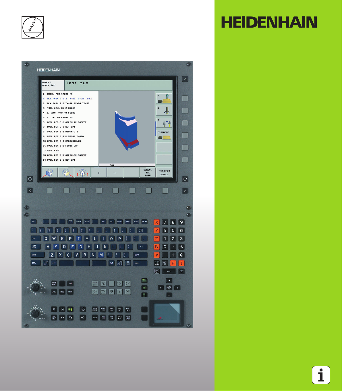
User’s Manual
ISO Programming
iTNC 530
NC Software
340 490-xx
340 491-xx
340 492-xx
340 493-xx
340 494-xx
English (en)
12/2005
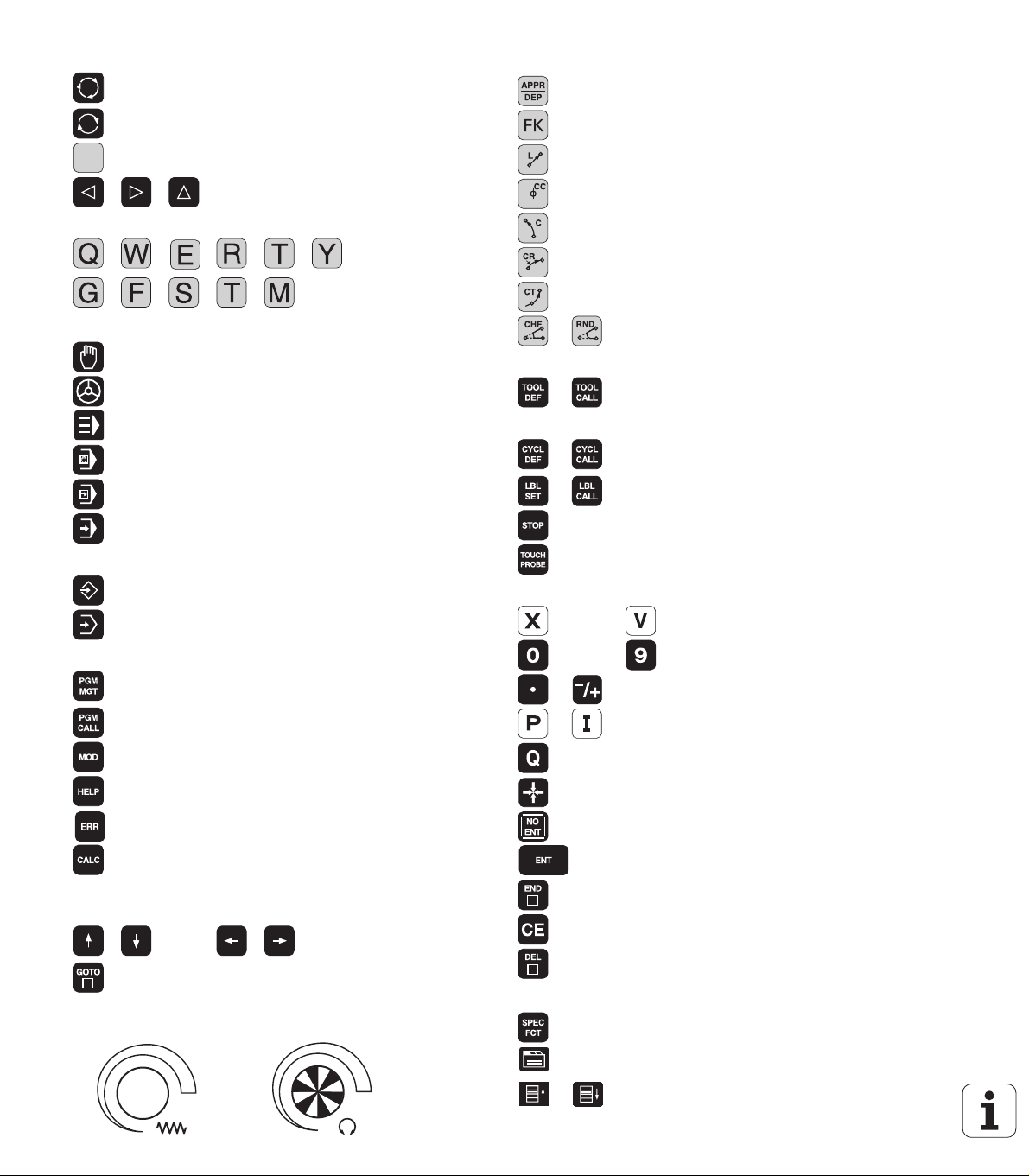
Controls on the visual display unit
Split screen layout
Switch between machining or
programming modes
Soft keys for selecting functions in
screen
Switch the soft-key rows
Programming path movements
Approach/depart contour
FK free contour programming
Straight line
Circle center/pole for polar coordinates
Typewriter keyboard for entering letters and symbols
File names
Comments
ISO
programs
Machine operating modes
Manual Operation
Electronic Handwheel
smarT.NC
Positioning with Manual Data Input (MDI)
Program Run, Single Block
Program Run, Full Sequence
Programming modes
Programming and Editing
Test Run
Program/file management, TNC functions
Select or delete programs and files
External data transfer
Define program call, select datum and point tables
Select MOD function
Display help texts for NC error messages
Display all current error messages
Pocket calculator
Circular arc with center
Circular arc with radius
Circular arc with tangential connection
Chamfer/corner rounding
Tool functions
Enter and call tool length and radius
Cycles, subprograms and program section repeats
Program stop in a program
Define touch probe cycles
Define and call cycles
Enter and call labels for subprogramming and
program section repeats
Coordinate axes and numbers: Entering and editing
. . .
. . .
Q parameter programming/Q parameter status
Assume actual position or values from calculator
Skip dialog questions, delete words
Decimal point / Reverse algebraic sign
Polar coordinate input/
Incremental dimensions
Confirm entry and resume dialog
Select coordinate axes or
enter them into the program
Numbers
Moving the highlight, going directly to blocks, cycles
and parameter functions
Go directly to blocks, cycles and parameter
Move highlight
functions
Override control knobs for feed rate/spindle speed
100
100
1
50
50
1
50
0
F %
0
50
S %
Conclude block, exit entry
Clear numerical entry or clear TNC error message
Abort dialog, delete program section
Special functions / smarT.NC
Show special functions
smarT.NC: Select next tab on form
smarT.NC: Select first input field in next/
previous frame


TNC Model, Software and Features
This manual describes functions and features provided by TNCs as of
the following NC software numbers.
TNC model NC software number
iTNC 530 340 490-02
iTNC 530 E 340 491-02
iTNC 530 340 492-02
iTNC 530 E 340 493-02
iTNC 530 programming station 340 494-02
The suffix E indicates the export version of the TNC. The export
version of the TNC has the following limitations:
Linear movement is possible in no more than 4 axes simultaneously.
The machine tool builder adapts the useable features of the TNC to his
machine by setting machine parameters. Some of the functions
described in this manual may not be among the features provided by
your machine tool.
TNC functions that may not be available on your machine include:
Tool measurement with the TT
Please contact your machine tool builder to become familiar with the
features of your machine.
Many machine manufacturers, as well as HEIDENHAIN, offer
programming courses for the TNCs. We recommend these courses as
an effective way of improving your programming skill and sharing
information and ideas with other TNC users.
Touch Probe Cycles User’s Manual:
All of the touch probe functions are described in a separate
manual. Please contact HEIDENHAIN if you need a copy of
this User’s Manual. Part number: 533 189-xx
User documentation:
The new smarT.NC operating mode is described in a
separate Pilot. Please contact HEIDENHAIN if you require
a copy of this Pilot. Part number: 533 191-xx.
HEIDENHAIN iTNC 530 5

Software options
The iTNC 530 features various software options that can be enabled
by you or your machine tool builder. Each option is to be enabled
separately and contains the following respective functions:
Software option 1
Cylinder surface interpolation (Cycles 27, 28, 29 and 39)
Feed rate in mm/min on rotary axes: M116
Tilting the machining plane (Cycle 19, PLANE function and 3-D ROT
soft key in the Manual operating mode)
Circle in 3 axes (with tilted working plane)
Software option 2
Block processing time 0.5 ms instead of 3.6 ms
5-axis interpolation
Spline interpolation
3-D machining:
M114: Automatic compensation of machine geometry when
working with tilted axes
M128: Maintaining the position of the tool tip when positioning
with tilted axes (TCPM)
FUNCTION TCPM: Maintaining the position of the tool tip when
positioning with tilted axes (TCPM) in selectable modes
M144: Compensating the machine’s kinematic configuration for
ACTUAL/NOMINAL positions at end of block
Additional parameters finishing/roughing and tolerance for
rotary axes in Cycle 32 (G62)
LN blocks (3-D compensation)
DXF Converter software option Description
Extract contours from DXF files (R12
format).
DCM software option Description
Function which monitors areas defined
by the machine manufacturer to
prevent collisions.
Additional dialog language software
option
Slovenian Page 581
6
Page 221
Page 83
Description

Feature content level (upgrade functions)
Along with software options, significant further improvements of the
TNC software are managed via the Feature Content Level. Functions
subject to the FCL are not available simply by updating the software
on your TNC. These functions are identified in the manual with FCL-n,
where n indicates the sequential number of the feature content level.
You can purchase a code number in order to permanently enable the
FCL functions. For more information, contact your machine tool
builder or HEIDENHAIN.
FCL-2 functions Description
3-D line graphics Page 131
Virtual tool axis Page 82
USB support of block devices (memory
sticks, hard disks, CD-ROM drives)
Filtering of externally created contours Conversational
Possibility of assigning different depths
to each subcontour in the contour
formula
DHCP dynamic IP-address
management
Touch-probe cycle for global setting of
touch-probe parameters
smarT.NC: Graphic support of block
scan
smarT.NC: Coordinate transformation smarT.NC Pilot
smarT.NC: PLANE function smarT.NC Pilot
Page 117
Programming User’s
Manual
Page 396
Page 552
Touch Probe Cycles
User’s Manual
smarT.NC Pilot
Location of use
The TNC complies with the limits for a Class A device in accordance
with the specifications in EN 55022, and is intended for use primarily
in industrially-zoned areas.
HEIDENHAIN iTNC 530 7

Functions new since the predecessor versions 340 422-xx and 340 423-xx
A new form-based operating mode, smarT.NC, has been
introduced. These cycles are described in a separate user's
document. In connection with this the TNC operating panel was
enhanced. There are some new keys available for quicker navigation
within smarT.NC (see “Operating panel” on page 41).
The single-processor versions supports pointing devices (mice) via
the USB 2.0 interface.
New CENTERING cycle (see “CENTERING (Cycle 240)” on page 274)
New M function M150 for suppressing limit switch messages (see
“Suppress limit switch message: M150” on page 249)
M128 is now also permitted for mid-program startup (see “Mid-
program startup (block scan)” on page 534).
The number of available Q parameters was expanded to 2000 (see
“Programming: Q Parameters” on page 483).
The number of available label numbers was expanded to 1000. Now
label names can be assigned as well (see “Labeling Subprograms
and Program Section Repeats” on page 468).
In the Q parameter functions D9 to D12 you can now also assign
label names as jump targets (see “If-Then Decisions with
Q Parameters” on page 492).
The current time is also shown in the additional status display
window (see “General program information” on page 46).
Several columns were added to the tool table (see “Tool table:
Standard tool data” on page 167).
The Test Run can now also be stopped and continued within
machining cycles (see “Running a program test” on page 528).
8

Functions changed since the predecessor versions 340 422-xx and 340 423-xx
The layouts of the status display and additional status display were
redesigned (see “Status Displays” on page 45).
Software 340 490 no longer supports the small resolution in
combination with the BC 120 screen (see “Visual display unit” on
page 39).
New key layout of the TE 530 B keyboard unit (see “Operating
panel” on page 41)
The tool types available for selection in the tool table were increased
in preparation for future functions.
HEIDENHAIN iTNC 530 9

New functions with 340 49x-02
DXF files can be opened directly on the TNC, in order to extract
contours into a plain-language program (see “Generating Contour
Programs from DXF Data (Software Option)” on page 221)
3-D line graphics are now available in the Programming and Editing
operating mode (see “3-D Line Graphics (FCL 2 Function)” on page
131)
The active tool-axis direction can now be set as the active machining
direction for manual operation (see “Setting the current tool-axis
direction as the active machining direction (FCL 2 function)” on page
82)
The machine manufacturer can now define any areas on the
machine for collision monitoring (see “Dynamic Collision Monitoring
(Software Option)” on page 83)
The TNC can now display freely definable tables in the familiar table
view or as forms (see “Switching between table and form view” on
page 191)
For contours which you connect via the contour formula, you can
now assign separate machining depths for each subcontour (see
“SL Cycles with Contour Formula” on page 396)
The single-processor version now supports not only pointing
devices (mice), but also USB block devices (memory sticks, disk
drives, hard disks, CD-ROM drives) (see “USB devices on the TNC
(FCL 2 function)” on page 117)
10

Functions changed in 340 49x-02
Access to the preset table was simplified. There are also new
possibilities for entering values in the preset table. See table
“Manually saving the datums in the preset table”
In inch-programs, the function M136 (feed rate in 0.1 inch/rev) can
no longer be combined with the function FU
The feed-rate potentiometers of the HR 420 are no longer switched
over automatically when the handwheel is selected. The selection is
made via soft key on the handwheel. In addition, the pop-up window
for the active handwheel was made smaller, in order to improve the
view of the display beneath it (see “Potentiometer settings” on
page 62)
The maximum number of contour elements for SL cycles was
increased to 8192, so that much more complex contours can be
machined (see “SL Cycles” on page 365)
FN16: F-PRINT: The maximum number of Q-parameter values that
can be output per line in the format description file was increased to
32 (Conversational Programming User's Manual).
The soft keys START and START SINGLE BLOCK in the Program
Test mode of operation were switched, so that the soft-key
alignment is the same in all modes of operation (Programming and
Editing, smarT.NC, Test) (see “Running a program test” on page
528)
The design of the soft keys was revised completely
HEIDENHAIN iTNC 530 11


Contents
Introduction
1
Manual Operation and Setup
Positioning with Manual Data Input
(MDI)
Programming: Fundamentals of File
Management, Programming Aids
Programming: Tools
Programming: Programming Contours
Programming: Miscellaneous Functions
Programming: Cycles
Programming: Special Functions
Programming: Subprograms and
Program Section Repeats
Programming: Q Parameters
Test Run and Program Run
MOD Functions
2
3
4
5
6
7
8
9
10
11
12
13
Tables and Overviews
iTNC 530 with Windows 2000 (Option)
HEIDENHAIN iTNC 530 13
14
15


1 Introduction ..... 37
1.1 The iTNC 530 ..... 38
Programming: HEIDENHAIN conversational, smarT.NC and ISO formats ..... 38
Compatibility ..... 38
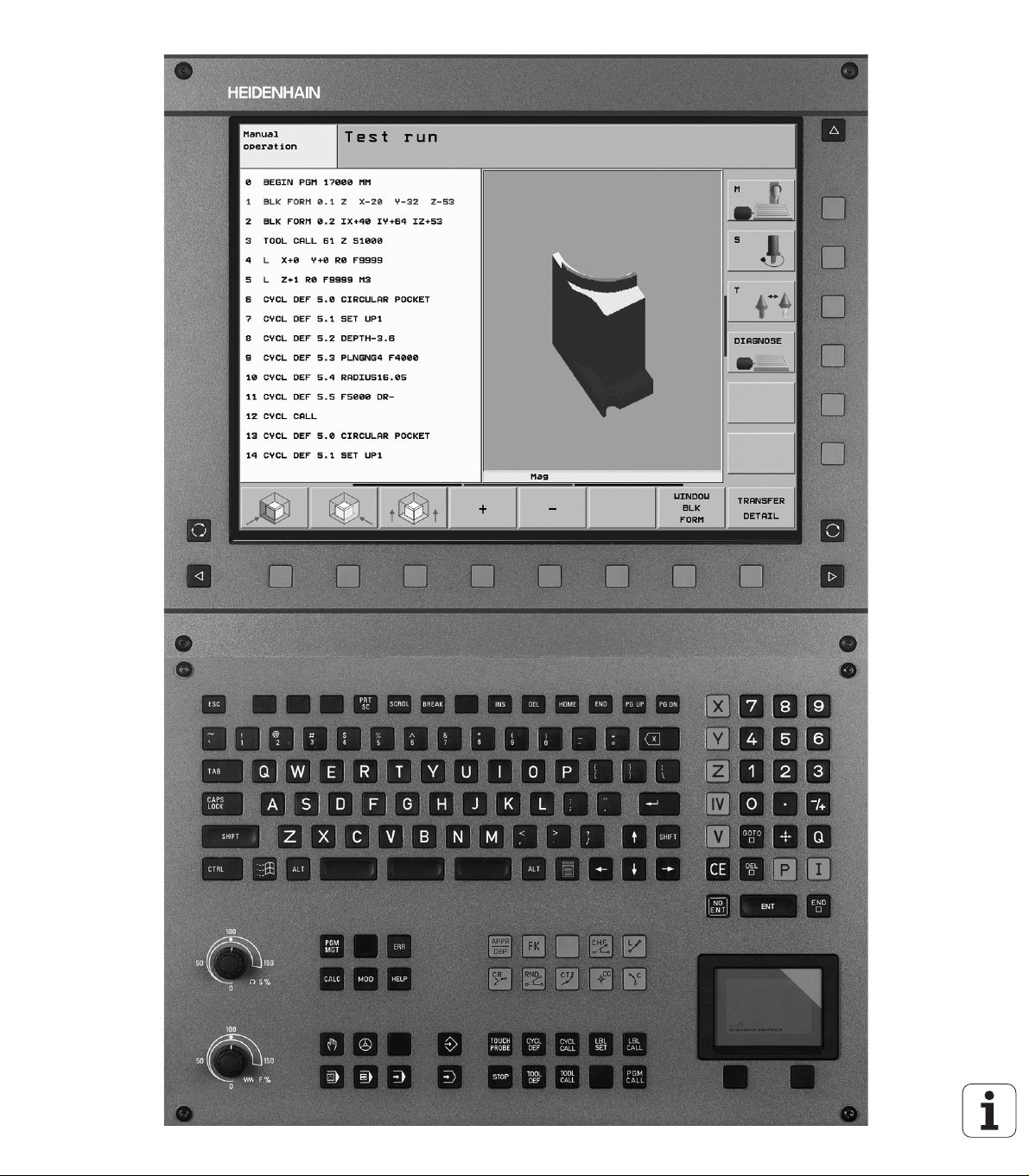
1.2 Visual Display Unit and Operating Panel ..... 39
Visual display unit ..... 39
Screen layout ..... 40
Operating panel ..... 41
1.3 Modes of Operation ..... 42
Manual operation and electronic handwheel ..... 42
Positioning with Manual Data Input (MDI) ..... 42
Programming and editing ..... 43
Test Run ..... 43
Program Run, Full Sequence and Program Run, Single Block ..... 44
1.4 Status Displays ..... 45
“General” status display ..... 45
Additional status displays ..... 46
1.5 Accessories: HEIDENHAIN 3-D Touch Probes and Electronic Handwheels ..... 50
3-D touch probes ..... 50
HR electronic handwheels ..... 51
HEIDENHAIN iTNC 530 15

2 Manual Operation and Setup ..... 53
2.1 Switch-On, Switch-Off ..... 54
Switch-on ..... 54
Switch-off ..... 56
2.2 Moving the Machine Axes ..... 57
Note ..... 57
To traverse with the machine axis direction buttons: ..... 57
Incremental jog positioning ..... 58
Traversing with the HR 410 electronic handwheel ..... 59
HR 420 electronic handwheel ..... 60
2.3 Spindle Speed S, Feed Rate F and Miscellaneous Functions M ..... 66
Function ..... 66
Entering values ..... 66
Changing the spindle speed and feed rate ..... 67
2.4 Datum Setting (Without a 3-D Touch Probe) ..... 68
Note ..... 68
Preparation ..... 68
Datum setting with axis keys ..... 69
Datum management with the preset table ..... 70
2.5 Tilting the Working Plane (Software Option 1) ..... 77
Application, function ..... 77
Traversing the reference points in tilted axes ..... 78
Setting the datum in a tilted coordinate system ..... 79
Datum setting on machines with rotary tables ..... 79
Datum setting on machines with spindle-head changing systems ..... 79
Position display in a tilted system ..... 80
Limitations on working with the tilting function ..... 80
Activating manual tilting ..... 81
Setting the current tool-axis direction as the active machining direction (FCL 2 function) ..... 82
2.6 Dynamic Collision Monitoring (Software Option) ..... 83
Function ..... 83
Collision monitoring in the manual operating modes ..... 83
Collision monitoring in Automatic operation ..... 85
16

3 Positioning with Manual Data Input (MDI) ..... 87
3.1 Programming and Executing Simple Machining Operations ..... 88
Positioning with Manual Data Input (MDI) ..... 88
Protecting and erasing programs in $MDI ..... 91
HEIDENHAIN iTNC 530 17

4 Fundamentals of NC, File Management, Programming Aids, Pallet Management ..... 93
4.1 Fundamentals ..... 94
Position encoders and reference marks ..... 94
Reference system ..... 94
Reference system on milling machines ..... 95
Polar coordinates ..... 96
Absolute and incremental workpiece positions ..... 97
Setting the datum ..... 98
4.2 File Management: Fundamentals ..... 99
Files ..... 99
Data backup ..... 100
4.3 Working with the File Manager ..... 101
Directories ..... 101
Paths ..... 101
Overview: Functions of the file manager ..... 102
Calling the file manager ..... 103
Selecting drives, directories and files ..... 104
Creating a new directory (only possible on the drive TNC:\) ..... 106
Copying a single file ..... 107
Copying a directory ..... 109
Choosing one of the last files selected ..... 109
Deleting a file ..... 110
Deleting a directory ..... 110
Tagging files ..... 111
Renaming a file ..... 112
Additional functions ..... 112
Data transfer to or from an external data medium ..... 113
Copying files into another directory ..... 115
The TNC in a network ..... 116
USB devices on the TNC (FCL 2 function) ..... 117
4.4 Creating and Writing Programs ..... 118
Organization of an NC program in ISO format ..... 118
Define blank form: G30/G31 ..... 118
Creating a new part program ..... 119
Programming tool movements ..... 121
Actual position capture ..... 122
Editing a program ..... 123
The TNC search function ..... 127
18

4.5 Interactive Programming Graphics ..... 129
Generating / Not generating graphics during programming: ..... 129
Generating a graphic for an existing program ..... 129
Block number display ON/OFF ..... 130
Erasing the graphic ..... 130
Magnifying or reducing a detail ..... 130
4.6 3-D Line Graphics (FCL 2 Function) ..... 131
Function ..... 131
Functions of the 3-D line graphics ..... 132
Highlighting NC blocks in the graphics ..... 134
Block number display ON/OFF ..... 134
Erasing the graphic ..... 134
4.7 Structuring Programs ..... 135
Definition and applications ..... 135
Displaying the program structure window / Changing the active window ..... 135
Inserting a structuring block in the (left) program window ..... 135
Selecting blocks in the program structure window ..... 135
4.8 Adding Comments ..... 136
Function ..... 136
Entering comments during programming ..... 136
Inserting comments after program entry ..... 136
Entering a comment in a separate block ..... 136
Functions for editing of the comment ..... 136
4.9 Creating Text Files ..... 137
Function ..... 137
Opening and exiting text files ..... 137
Editing texts ..... 138
Deleting and inserting characters, words and lines ..... 139
Editing text blocks ..... 140
Finding text sections ..... 141
HEIDENHAIN iTNC 530 19

4.10 Integrated Pocket Calculator ..... 142
Operation ..... 142
4.11 Immediate Help for NC Error Messages ..... 143
Displaying error messages ..... 143
Display HELP ..... 143
4.12 List of All Current Error Messages ..... 144
Function ..... 144
Show error list ..... 144
Window contents ..... 145
4.13 Pallet Management ..... 146
Function ..... 146
Selecting a pallet table ..... 148
Leaving the pallet file ..... 148
Executing the pallet file ..... 149
4.14 Pallet Operation with Tool-Oriented Machining ..... 150
Function ..... 150
Selecting a pallet file ..... 154
Setting up the pallet file with the entry form ..... 155
Sequence of tool-oriented machining ..... 159
Leaving the pallet file ..... 160
Executing the pallet file ..... 160
20

5 Programming: Tools ..... 163
5.1 Entering Tool-Related Data ..... 164
Feed rate F ..... 164
Spindle speed S ..... 164
5.2 Tool Data ..... 165
Requirements for tool compensation ..... 165
Tool numbers and tool names ..... 165
Tool length L ..... 165
Tool radius R ..... 166
Delta values for lengths and radii ..... 166
Entering tool data into the program ..... 166
Entering tool data in tables ..... 167
Using an external PC to overwrite individual tool data ..... 173
Pocket table for tool changer ..... 174
Calling tool data ..... 177
Tool change ..... 178
5.3 Tool Compensation ..... 180
Introduction ..... 180
Tool length compensation ..... 180
Tool radius compensation ..... 181
5.4 Peripheral Milling: 3-D Radius Compensation with Workpiece Orientation ..... 184
Function ..... 184
5.5 Working with Cutting Data Tables ..... 185
Note ..... 185
Applications ..... 185
Table for workpiece materials ..... 186
Table for tool cutting materials ..... 187
Table for cutting data ..... 187
Data required for the tool table ..... 188
Working with automatic speed / feed rate calculation ..... 189
Changing the table structure ..... 190
Switching between table and form view ..... 191
Data transfer from cutting data tables ..... 192
Configuration file TNC.SYS ..... 192
HEIDENHAIN iTNC 530 21

6 Programming: Programming Contours ..... 193
6.1 Tool Movements ..... 194
Path functions ..... 194
Miscellaneous functions M ..... 194
Subprograms and program section repeats ..... 194
Programming with Q parameters ..... 194
6.2 Fundamentals of Path Functions ..... 195
Programming tool movements for workpiece machining ..... 195
6.3 Contour Approach and Departure ..... 197
Starting point and end point ..... 197
Tangential approach and departure ..... 199
6.4 Path Contours—Cartesian Coordinates ..... 201
Overview of path functions ..... 201
Straight line at rapid traverse G00
Straight line with feed rate G01 F. . . ..... 202
Inserting a chamfer between two straight lines ..... 203
Rounding corners G25 ..... 204
Circle center I, J ..... 205
Circular path G02/G03/G05 around circle center I, J ..... 206
Circular path G02/G03/G05 with defined radius ..... 207
Circular path G06 with tangential approach ..... 209
6.5 Path Contours—Polar Coordinates ..... 214
Overview of path functions with polar coordinates ..... 214
Zero point for polar coordinates: pole I, J ..... 214
Straight line at rapid traverse G10
Straight line with feed rate G11 F . . . ..... 215
Circular path G12/G13/G15 around pole I, J ..... 215
Circular arc G16 with tangential connection ..... 216
Helical interpolation ..... 216
6.6 Generating Contour Programs from DXF Data (Software Option) ..... 221
Function ..... 221
Opening a DXF file ..... 221
Basic settings ..... 222
Layer settings ..... 223
Datum specifying ..... 224
Contour selection, saving a contour program ..... 226
Zoom function ..... 227
22

7 Programming: Miscellaneous Functions ..... 229
7.1 Entering Miscellaneous Functions M and G38 ..... 230
Fundamentals ..... 230
7.2 Miscellaneous Functions for Program Run Control, Spindle and Coolant ..... 231
Overview ..... 231
7.3 Miscellaneous Functions for Coordinate Data ..... 232
Programming machine-referenced coordinates: M91/M92 ..... 232
Activating the most recently entered datum: M104 ..... 234
Moving to positions in a non-tilted coordinate system with a tilted working plane: M130 ..... 234
7.4 Miscellaneous Functions for Contouring Behavior ..... 235
Smoothing corners: M90 ..... 235
Insert rounding arc between straight lines: M112 ..... 236
Do not include points when executing non-compensated line blocks: M124 ..... 236
Machining small contour steps: M97 ..... 237
Machining open contours: M98 ..... 239
Feed rate factor for plunging movements: M103 ..... 240
Feed rate in millimeters per spindle revolution: M136 ..... 241
Feed rate for circular arcs: M109/M110/M111 ..... 242
Calculating the radius-compensated path in advance (LOOK AHEAD): M120 ..... 242
Superimposing handwheel positioning during program run: M118 ..... 244
Retraction from the contour in the tool-axis direction: M140 ..... 245
Suppressing touch probe monitoring: M141 ..... 246
Delete modal program information: M142 ..... 247
Delete basic rotation: M143 ..... 247
Automatically retract tool from the contour at an NC stop: M148 ..... 248
Suppress limit switch message: M150 ..... 249
7.5 Miscellaneous Functions for Rotary Axes ..... 250
Feed rate in mm/min on rotary axes A, B, C: M116 (software option 1) ..... 250
Shorter-path traverse of rotary axes: M126 ..... 251
Reducing display of a rotary axis to a value less than 360°: M94 ..... 252
Automatic compensation of machine geometry when working with tilted axes: M114 (software option 2) ..... 253
Maintaining the position of the tool tip when positioning with tilted axes (TCPM): M128 (software
option 2) ..... 254
Exact stop at corners with nontangential transitions: M134 ..... 256
Selecting tilting axes: M138 ..... 256
Compensating the machine’s kinematic configuration for ACTUAL/NOMINAL positions at end of block: M144
(software option 2) ..... 257
HEIDENHAIN iTNC 530 23

7.6 Miscellaneous Functions for Laser Cutting Machines ..... 258
Principle ..... 258
Output the programmed voltage directly: M200 ..... 258
Output voltage as a function of distance: M201 ..... 258
Output voltage as a function of speed: M202 ..... 259
Output voltage as a function of time (time-dependent ramp): M203 ..... 259
Output voltage as a function of time (time-dependent pulse): M204 ..... 259
24

8 Programming: Cycles ..... 261
8.1 Working with Cycles ..... 262
Machine-specific cycles ..... 262
Defining a cycle using soft keys ..... 263
Calling a cycle ..... 265
Calling a cycle with G79 (CYCL CALL) ..... 265
Calling a cycle with G79 PAT (CYCL CALL PAT) ..... 265
Calling a cycle with G79:G01 (CYCL CALL POS) ..... 266
Calling a cycle with M99/89 ..... 266
Working with the secondary axes U/V/W ..... 267
8.2 Point Tables ..... 268
Function ..... 268
Creating a point table ..... 268
Hiding single points from the machining process ..... 269
Selecting a point table in the program ..... 269
Calling a cycle in connection with point tables ..... 270
8.3 Cycles for Drilling, Tapping and Thread Milling ..... 272
Overview ..... 272
CENTERING (Cycle 240) ..... 274
DRILLING (Cycle G200) ..... 276
REAMING (Cycle G201) ..... 278
BORING (Cycle G202) ..... 280
UNIVERSAL DRILLING (Cycle G203) ..... 282
BACK BORING (Cycle G204) ..... 284
UNIVERSAL PECKING (Cycle G205) ..... 287
BORE MILLING (Cycle G208) ..... 290
TAPPING NEW with floating tap holder (Cycle G206) ..... 292
RIGID TAPPING NEW (Cycle G207) ..... 294
TAPPING WITH CHIP BREAKING (Cycle G209) ..... 296
Fundamentals of thread milling ..... 298
THREAD MILLING (Cycle G262) ..... 300
THREAD MILLING/COUNTERSINKING (Cycle G263) ..... 302
THREAD DRILLING/MILLING (Cycle G264) ..... 306
HELICAL THREAD DRILLING/MILLING (Cycle G265) ..... 310
OUTSIDE THREAD MILLING (Cycle G267) ..... 314
HEIDENHAIN iTNC 530 25

8.4 Cycles for Milling Pockets, Studs and Slots ..... 323
Overview ..... 323
RECTANGULAR POCKET (Cycle G251) ..... 324
CIRCULAR POCKET (Cycle G252) ..... 329
SLOT MILLING (Cycle 253) ..... 333
CIRCULAR SLOT (Cycle 254) ..... 338
POCKET FINISHING (Cycle G212) ..... 343
STUD FINISHING (Cycle G213) ..... 345
CIRCULAR POCKET FINISHING (Cycle G214) ..... 347
CIRCULAR STUD FINISHING (Cycle G215) ..... 349
SLOT with reciprocating plunge-cut (Cycle G210) ..... 351
CIRCULAR SLOT with reciprocating plunge-cut (Cycle G211) ..... 353
8.5 Cycles for Machining Point Patterns ..... 358
Overview ..... 358
CIRCULAR PATTERN (Cycle G220) ..... 359
LINEAR PATTERN (Cycle G221) ..... 361
8.6 SL Cycles ..... 365
Fundamentals ..... 365
Overview of SL Cycles ..... 367
CONTOUR GEOMETRY (Cycle G37) ..... 368
Overlapping contours ..... 369
CONTOUR DATA (Cycle G120) ..... 372
PILOT DRILLING (Cycle G121) ..... 373
ROUGH-OUT (Cycle G122) ..... 374
FLOOR FINISHING (Cycle G123) ..... 375
SIDE FINISHING (Cycle G124) ..... 376
CONTOUR TRAIN (Cycle G125) ..... 377
CYLINDER SURFACE (Cycle G127, software option 1) ..... 379
CYLINDER SURFACE slot milling (Cycle G128, software option 1) ..... 381
CYLINDER SURFACE ridge milling (Cycle G129, software option 1) ..... 383
CYLINDER SURFACE outside contour milling (Cycle G139, software option 1) ..... 385
8.7 SL Cycles with Contour Formula ..... 396
Fundamentals ..... 396
Selecting a program with contour definitions ..... 397
Defining contour descriptions ..... 397
Entering a contour formula ..... 398
Overlapping contours ..... 399
Contour machining with SL Cycles ..... 401
26

8.8 Cycles for Multipass Milling ..... 405
Overview ..... 405
RUN 3-D DATA (Cycle G60) ..... 406
MULTIPASS MILLING (Cycle G230) ..... 407
RULED SURFACE (Cycle G231) ..... 409
FACE MILLING (Cycle 232) ..... 412
8.9 Coordinate Transformation Cycles ..... 419
Overview ..... 419
Effect of coordinate transformations ..... 419
DATUM SHIFT (Cycle G54) ..... 420
DATUM SHIFT with datum tables (Cycle G53) ..... 421
DATUM SETTING (Cycle G247) ..... 425
MIRROR IMAGE (Cycle G28) ..... 426
ROTATION (Cycle G73) ..... 428
SCALING FACTOR (Cycle G72) ..... 429
WORKING PLANE (Cycle G80, software option1) ..... 430
8.10 Special Cycles ..... 437
DWELL TIME (Cycle G04) ..... 437
PROGRAM CALL (Cycle G39) ..... 438
ORIENTED SPINDLE STOP (Cycle G36) ..... 439
TOLERANCE (Cycle G62) ..... 440
HEIDENHAIN iTNC 530 27

9 Programming: Special Functions ..... 443
9.1 The PLANE Function: Tilting the Working Plane (Software Option 1) ..... 444
Introduction ..... 444
Define the PLANE function ..... 446
Position display ..... 446
Reset the PLANE function ..... 447
9.2 Defining the Machining Plane with Space Angles: PLANE SPATIAL ..... 448
Function ..... 448
Input parameters ..... 449
9.3 Defining the Machining Plane with Projection Angles: PROJECTED PLANE ..... 450
Function ..... 450
Input parameters ..... 451
9.4 Defining the Machining Plane with Euler Angles: PLANE EULER ..... 452
Function ..... 452
Input parameters ..... 453
9.5 Defining the Machining Plane with Two Vectors: VECTOR PLANE ..... 454
Function ..... 454
Input parameters ..... 455
9.6 Defining the Machining Plane via Three Points: POINTS PLANE ..... 456
Function ..... 456
Input parameters ..... 457
9.7 Defining the Machining Plane with a Single, Incremental Space Angle: PLANE RELATIVE ..... 458
Function ..... 458
Input parameters ..... 459
Abbreviations used ..... 459
9.8 Specifying the Positioning Behavior of the PLANE Function ..... 460
Overview ..... 460
Automatic positioning: MOVE/TURN/STAY (entry is mandatory) ..... 461
Selection of alternate tilting possibilities: SEQ +/– (entry optional) ..... 464
Selecting the type of transformation (entry optional) ..... 465
9.9 Inclined-Tool Machining in the Tilted Plane ..... 466
Function ..... 466
Inclined-tool machining via incremental traverse of a rotary axis ..... 466
28

10 Programming: Subprograms and Program Section Repeats ..... 467
10.1 Labeling Subprograms and Program Section Repeats ..... 468
Labels ..... 468
10.2 Subprograms ..... 469
Operating sequence ..... 469
Programming notes ..... 469
Programming a subprogram ..... 469
Calling a subprogram ..... 469
10.3 Program Section Repeats ..... 470
Label G98 ..... 470
Operating sequence ..... 470
Programming notes ..... 470
Programming a program section repeat ..... 470
Calling a program section repeat ..... 470
10.4 Separate Program as Subprogram ..... 471
Operating sequence ..... 471
Programming notes ..... 471
Calling any program as a subprogram ..... 472
10.5 Nesting ..... 473
Types of nesting ..... 473
Nesting depth ..... 473
Subprogram within a subprogram ..... 473
Repeating program section repeats ..... 474
Repeating a subprogram ..... 475
HEIDENHAIN iTNC 530 29

11 Programming: Q Parameters ..... 483
11.1 Principle and Overview ..... 484
Programming notes ..... 485
Calling Q parameter functions ..... 485
11.2 Part Families—Q Parameters in Place of Numerical Values ..... 486
Example NC blocks ..... 486
Example ..... 486
11.3 Describing Contours through Mathematical Operations ..... 487
Function ..... 487
Overview ..... 487
Programming fundamental operations ..... 488
11.4 Trigonometric Functions ..... 490
Definitions ..... 490
Programming trigonometric functions ..... 491
11.5 If-Then Decisions with Q Parameters ..... 492
Function ..... 492
Unconditional jumps ..... 492
Programming If-Then decisions ..... 492
Abbreviations used: ..... 493
11.6 Checking and Changing Q Parameters ..... 494
Procedure ..... 494
11.7 Additional Functions ..... 495
Overview ..... 495
D14: ERROR: Output error messages ..... 496
D15: PRINT: Output of texts or Q parameter values ..... 498
D19: PLC: Transfer values to the PLC ..... 498
11.8 Entering Formulas Directly ..... 499
Entering formulas ..... 499
Rules for formulas ..... 501
Programming example ..... 502
30
Loading...