


UC2871QTR
Texas Instruments UC2871QTR, UC2871Q, UC2871N, UC2871J, UC2871DWTR Datasheet
...
10/94
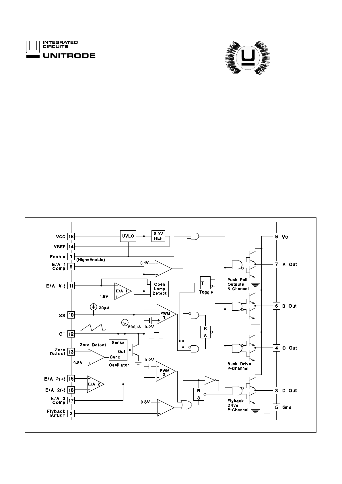
BLOCK DIAGRAM
• 1µA ICC when Disabled
• PWM Control for LCD Supply
• Zero Voltage Switched (ZVS) on
Push-Pull Drivers
• Open Lamp Detect Circuitry
• 4.5V to 20V Operation
• Non-saturating Transformer
Topology
• Smooth 100% Duty Cycle on
Buck PWM and 0% to 95% on
Flyback PWM
The UC1871 Famil y of IC’s is optimized for highly efficient fl uorescent lamp
control. An additional PWM controller is integrated on the IC for applications re-
quiring an additional suppl y, as in LCD displays . When disabled the IC draws
only 1µA, providing a true disconnect feature, which is optimum for battery
powered systems. The switching frequency of all outputs are synchronized to
the resonant frequency of the e xternal passive network, which provides Zero
V oltage Switching on the Push-Pull drivers.
Soft-Start and open lamp detect circuitry have been incorporated to minimize
component stress. An open lamp i s detected on the compl etion of a soft-start
cycle.
The Buck control ler is optimized for smooth duty cycle control to 100%, while
the flyback control ensures a maximum duty cycle of 95%.
Other features include a precision 1% reference, under voltage lockout, flyback
current limit, and accurate minimum and maximum frequency control.
Resonant Fluorescent Lamp Driver
FEATURES
DESCRIPTION
UDG-92061-1
UC1871
UC2871
UC3871
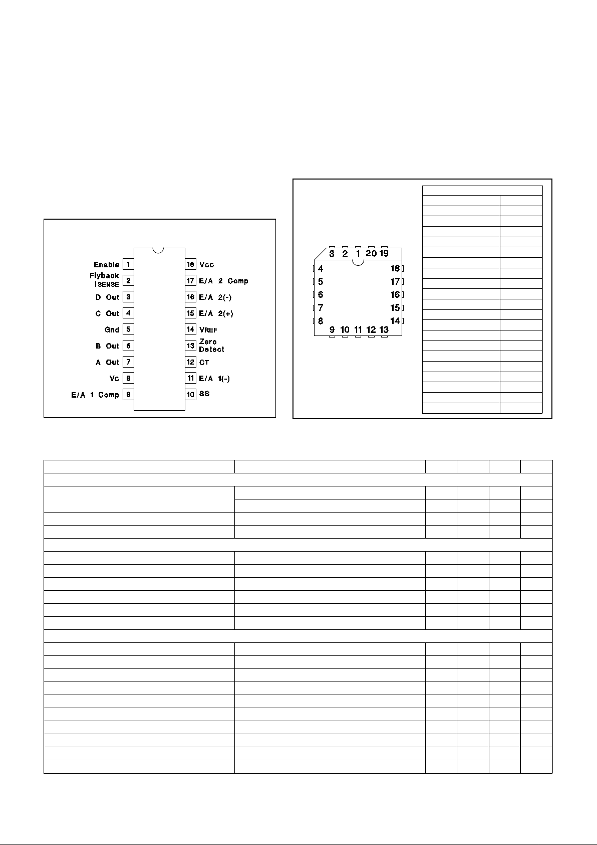
Note: Pin number s refer to DIL- 18 an d SOIC- 18 pa ckag es only.
PARAMETER TEST CONDITION S MIN TYP MAX UNITS
Reference Sect ion
Output Voltage T
J=25°C 2.963 3.000 3.037 V
Overtemp 2.940 3.000 3.060 V
Line Regulation V
CC = 4.75V to 18V 10 mV
Load Regulat io n Io=0 to -5mA 10 mV
Oscillator Section
Free Running Freq T
J=25°C 576878kHz
Max Sync Frequency T
J=25°C 160 200 240 kHz
Charge Curr ent V
CT = 1.5V 180 200 220 µA
Voltage Sta bi lity 2%
Temperature Stability 48%
Zero Detect Threshold 0.46 0.5 0.56 V
Error Amp 1 Sectio n
Input Voltage V
O = 2V 1.445 1.475 1.505 V
Input Bias Current -0.4 -2 µA
Open Loo p Ga in V
O = 0.5 to 3V 65 90 dB
Output High V
EA(-) = 1.3V 3.1 3.5 3.9 V
Output Low V
EA(-) = 1.7V 0.1 0.2 V
Output Source Current V
EA(-) = 1.3V, Vo = 2V -350 -500 µA
Output Sink Current V
EA(-) = 1.7V, Vo = 2V 10 20 mA
Common Mode Range 0V
IN-1V V
Unity Gain Bandwidth T
J = 25°C (Note 4) 1 MHz
Maximum Source Im peda nce Note 5 100k Ω
UC1871
UC2871
UC3871
ELECTRICAL CHARACTERIST ICS
Unless otherwise stated , thes e par am eters apply f or TA = -55°C to +125°C for the
UC1871; -25°C to +85°C for the UC2 871; 0°C t o +70°C f or the UC3871; V
CC = 5V,
V
C = 15V, VENABLE = 5V, CT = 1nF , Z ero Det = 1V.
ABSOLUTE MAXIMUM RATINGS
Analog Inputs . . . . . . . . . . . . . . . . . . . . . . . . . −0.3 to +10V
V
CC, VC Voltage . . . . . . . . . . . . . . . . . . . . . . . . . . . . . +20V
Zero Detect I nput Current
High Impedanc e Source . . . . . . . . . . . . . . . . . . +10mA
Zero Detect
Low Impedance Source. . . . . . . . . . . . . . . . . . . . . +20V
Power Dissipation at T
A = 25°C . . . . . . . . . . . . . . . . . . . 1W
Storage T e mperature. . . . . . . . . . . . . . . . -65 °C to +150°C
Lead Temp erature . . . . . . . . . . . . . . . . . . . . . . . . . . 300°C
Note 1: Current s are pos itive int o, nega tive out of the sp ecif ied te r-
minal.
Note 2: Consult Packaging Sec tion of Databook f or therma l
limitations and considerations of package.
DIL-18, SOIC-18 ( TOP VIEW)
J or N, DW Package
PACKAGE PIN FUNCTION
FUNCTION PIN
Gnd 1
B Out 2
A Out 3
VC 4
E/A 1 Comp 5
SS 6
E/A 1(-) 7
N/C 8
C
T 9
Zero Detect 10
N/C 11
VREF 12
E/A 2(+) 13
E/A 2(-) 14
E/A 2 Comp 15
V
CC 16
Enable 17
Flyback I
SENSE 18
D Out 19
C Out 20
PLCC-20 (Top View)
Q Package
CONNECTION DIAG RAMS
2
 Loading...