


TSB14C01 5-V IEEE 1394-1995 BACKPLANE TRANSCEIVER/ARBITER
|
SLLS231B ± MARCH 1996 ± REVISED MAY 1997 |
|
|
|
|
D Supports Provisions of IEEE 1394-1995 |
D Separate Transmitter and Receiver for |
|
(1394) Standard for High-Performance |
Greater Flexibility |
|
Serial Bus² |
D Data Interface to Link-Layer Controller |
|
D Fully Interoperable With FireWire |
||
(Link) Provided Through Two Parallel |
||
Implementation of 1394 |
Signal Lines at 25/50 MHz |
|
D Provides A Backplane Environment That |
D 100-MHz or 50-MHz Oscillator Provides |
|
Supports 50 or 100 Megabits per Second |
Transmit, Receive-Data, and Link Clocks at |
|
(Mbits/s) |
25/50 MHz |
|
D Logic Performs System Initialization and |
D Single 5-V Supply Operation |
|
Arbitration Functions |
D Packaged in a High-Performance 64-Pin |
|
D Encode and Decode Functions Included for |
TQFP (PM) Package for 0°C to 70°C |
|
Data-Strobe Bit-Level Encoding |
Operation |
|
D Incoming Data Resynchronized to Local |
D Packaged in a 68-Pin CFP (HV) Package for |
|
Clock |
±55°C to 125°C Operation |
description
The TSB14C01 provides the transceiver functions needed to implement a single port node in a backplanebased 1394 network. The TSB14C01 provides two terminals for transmitting, two terminals for receiving, and a single terminal to externally control the drivers for data and strobe. The TSB14C01 is not designed to drive the backplane directly, this function must be provided externally. The TSB14C01 is designed to interface with a link-layer controller (link), such as the TSB12C01A.
The TSB14C01 requires an external 98.304-MHz or 49.152-MHz reference oscillator input for S100/50 operation. The reference signal is internally divided to provide the 49.152-MHz ±100-ppm system clock signals used to control transmission of the outbound encoded strobe and data information. The 49.152-MHz clock signal is supplied to the associated link for synchronization of the two chips, when this device is in the S100 mode of operation, OSC_SEL is asserted high. When the TSB14C01 is in the S50 mode of operation, the clock rate supplied to the link is 24.576 MHz.
Data bits to be transmitted are received from the link on two parallel paths and are latched internally in the TSB14C01 in synchronization with the 49.152-MHz system clock. These bits are combined serially, encoded, and then transmitted at 98.304-Mbits/s (in S100 mode) as the outbound data-strobe information stream. During transmission, the encoded data information is transmitted on TDATA, and the encoded strobe information is transmitted on TSTRB.
During packet reception the encoded information is received on RDATA and strobe information on RSTRB. The received data-strobe information is decoded to recover the receive clock signal and the serial data bits. The serial data bits are split into two parallel streams, resynchronized to the local system clock, and sent to the associated link.
The TSB14C01 is a 5-V device and provides CMOS-level outputs.
AVAILABLE OPTIONS
|
PACKAGES |
|
TA |
|
|
CERAMIC FLAT PACK |
THIN QUAD FLAT PACK |
|
|
(HV) |
(PM) |
|
|
|
0°C to 70°C |
Ð |
TSB14C01PM |
|
|
|
± 55°C to 125°C |
TSB14C01MHV |
Ð |
|
|
|
Please be aware that an important notice concerning availability, standard warranty, and use in critical applications of Texas Instruments semiconductor products and disclaimers thereto appears at the end of this data sheet.
² This serial bus implements technology covered by one or more patents of Apple Computer, Incorporated and SGS Thomson, Limited. FireWire is a trademark of Apple Computer, Incorporated.
PRODUCTION DATA information is current as of publication date. Products conform to specifications per the terms of Texas Instruments standard warranty. Production processing does not necessarily include testing of all parameters.
Copyright 1997, Texas Instruments Incorporated
POST OFFICE BOX 655303 •DALLAS, TEXAS 75265 |
1 |
TSB14C01
5-V IEEE 1394-1995 BACKPLANE TRANSCEIVER/ARBITER
SLLS231B ± MARCH 1996 ± REVISED MAY 1997
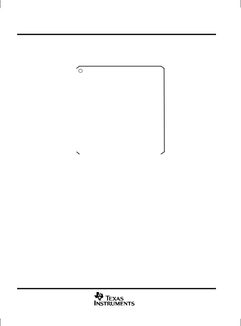
PM PACKAGE (TOP VIEW)
|
|
|
|
GND |
RPREFIX |
V |
|
V |
GND |
V |
TI1 V NC _XI50 |
GND |
NC |
|
_XI100 GND OSC_SEL |
|
GND |
|
|
||||||||||||||||||||
|
|
|
|
|
|
|
|
CC |
|
CC |
|
|
CC |
|
|
CC |
|
|
|
|
|
|
|
|
|
|
|
|
|
|
|
|
|||||||
|
|
|
|
|
|
|
|
|
|
|
|
|
|
|
|
|
|
|
|
|
|
|
|
|
|
|
|
|
|
|
|
|
|
|
|
|
|
|
|
ARB_CLK |
|
|
64 63 62 61 60 59 58 57 56 55 54 53 52 51 50 49 |
|
|
|
NC |
||||||||||||||||||||||||||||||||
|
|
1 |
|
|
|
|
|
|
|
|
|
|
|
|
|
|
|
|
|
|
|
|
|
|
|
|
|
|
|
|
|
48 |
|
||||||
PHYENA |
|
|
2 |
|
|
|
|
|
|
|
|
|
|
|
|
|
|
|
|
|
|
|
|
|
|
|
|
|
|
|
|
|
47 |
|
NC |
||||
|
|
|
|
|
|
|
|
|
|
|
|
|
|
|
|
|
|
|
|
|
|
|
|
|
|
|
|
|
|
|
|
||||||||
VCC |
|
|
3 |
|
|
|
|
|
|
|
|
|
|
|
|
|
|
|
|
|
|
|
|
|
|
|
|
|
|
|
|
|
46 |
|
NC |
||||
|
|
|
|
|
|
|
|
|
|
|
|
|
|
|
|
|
|
|
|
|
|
|
|
|
|
|
|
|
|
|
|
||||||||
ENA_PRI |
|
|
4 |
|
|
|
|
|
|
|
|
|
|
|
|
|
|
|
|
|
|
|
|
|
|
|
|
|
|
|
|
|
45 |
|
NC |
||||
|
|
|
|
|
|
|
|
|
|
|
|
|
|
|
|
|
|
|
|
|
|
|
|
|
|
|
|
|
|
|
|
||||||||
VCC |
|
|
5 |
|
|
|
|
|
|
|
|
|
|
|
|
|
|
|
|
|
|
|
|
|
|
|
|
|
|
|
|
|
44 |
|
NC |
||||
|
|
|
|
|
|
|
|
|
|
|
|
|
|
|
|
|
|
|
|
|
|
|
|
|
|
|
|
|
|
|
|
||||||||
N_POR |
|
|
6 |
|
|
|
|
|
|
|
|
|
|
|
|
|
|
|
|
|
|
|
|
|
|
|
|
|
|
|
|
|
43 |
|
RDATA |
||||
|
|
|
|
|
|
|
|
|
|
|
|
|
|
|
|
|
|
|
|
|
|
|
|
|
|
|
|
|
|
|
|
||||||||
GND |
|
|
7 |
|
|
|
|
|
|
|
|
|
|
|
|
|
|
|
|
|
|
|
|
|
|
|
|
|
|
|
|
|
42 |
|
RSTRB |
||||
LREQ |
|
|
8 |
|
|
|
|
|
|
|
|
|
|
|
|
TSB14C01 |
|
|
|
|
|
|
|
|
|
41 |
|
VCC |
|||||||||||
VCC |
|
|
9 |
|
|
|
|
|
|
|
|
|
|
|
|
|
|
|
|
|
|
|
|
|
40 |
|
TDATA |
||||||||||||
|
|
|
|
|
|
|
|
|
|
|
|
|
|
|
|
|
|
|
|
|
|
|
|
|
|
|
|
|
|
|
|
||||||||
SCLK |
|
|
10 |
|
|
|
|
|
|
|
|
|
|
|
|
|
|
|
|
|
|
|
|
|
|
|
|
|
|
|
|
39 |
|
TSTRB |
|||||
TSCLK |
|
|
11 |
|
|
|
|
|
|
|
|
|
|
|
|
|
|
|
|
|
|
|
|
|
|
|
|
|
|
|
|
38 |
|
GND |
|||||
GND |
|
|
12 |
|
|
|
|
|
|
|
|
|
|
|
|
|
|
|
|
|
|
|
|
|
|
|
|
|
|
|
|
37 |
|
N_OEB_D |
|||||
CTL0 |
|
|
13 |
|
|
|
|
|
|
|
|
|
|
|
|
|
|
|
|
|
|
|
|
|
|
|
|
|
|
|
|
36 |
|
GND |
|||||
CTL1 |
|
|
14 |
|
|
|
|
|
|
|
|
|
|
|
|
|
|
|
|
|
|
|
|
|
|
|
|
|
|
|
|
35 |
|
PTEST_INDRV |
|||||
D0 |
|
|
15 |
|
|
|
|
|
|
|
|
|
|
|
|
|
|
|
|
|
|
|
|
|
|
|
|
|
|
|
|
34 |
|
VCC |
|||||
D1 |
|
|
16 |
|
|
|
|
|
|
|
|
|
|
|
|
|
|
|
|
|
|
|
|
|
|
|
|
|
|
|
|
33 |
|
NC |
|||||
|
|
|
1718 19 |
20 21 22 23 24 25 26 27 28 |
29 30 31 |
32 |
|
|
|
|
|
||||||||||||||||||||||||||||
|
|
|
|
|
|
|
|
|
|
|
|
|
|
|
|
|
|
|
|
|
|
|
|
|
|
|
|
|
|
|
|
|
|
|
|
|
|
|
|
|
|
|
|
CC |
EN EXID |
EN EXPRI |
|
EX ID5 |
EX ID4 |
EX ID3 |
EX ID2 EX ID1 EX ID0 GND |
EX PRI3 |
EX PRI2 |
|
EX PRI1 EX PRI0 NC |
|
NC |
|
|
||||||||||||||||||||
|
|
|
|
V |
|
|
|
|
|
||||||||||||||||||||||||||||||
NC ± No connection
2 |
POST OFFICE BOX 655303 •DALLAS, TEXAS 75265 |

TSB14C01 5-V IEEE 1394-1995 BACKPLANE TRANSCEIVER/ARBITER
SLLS231B ± MARCH 1996 ± REVISED MAY 1997
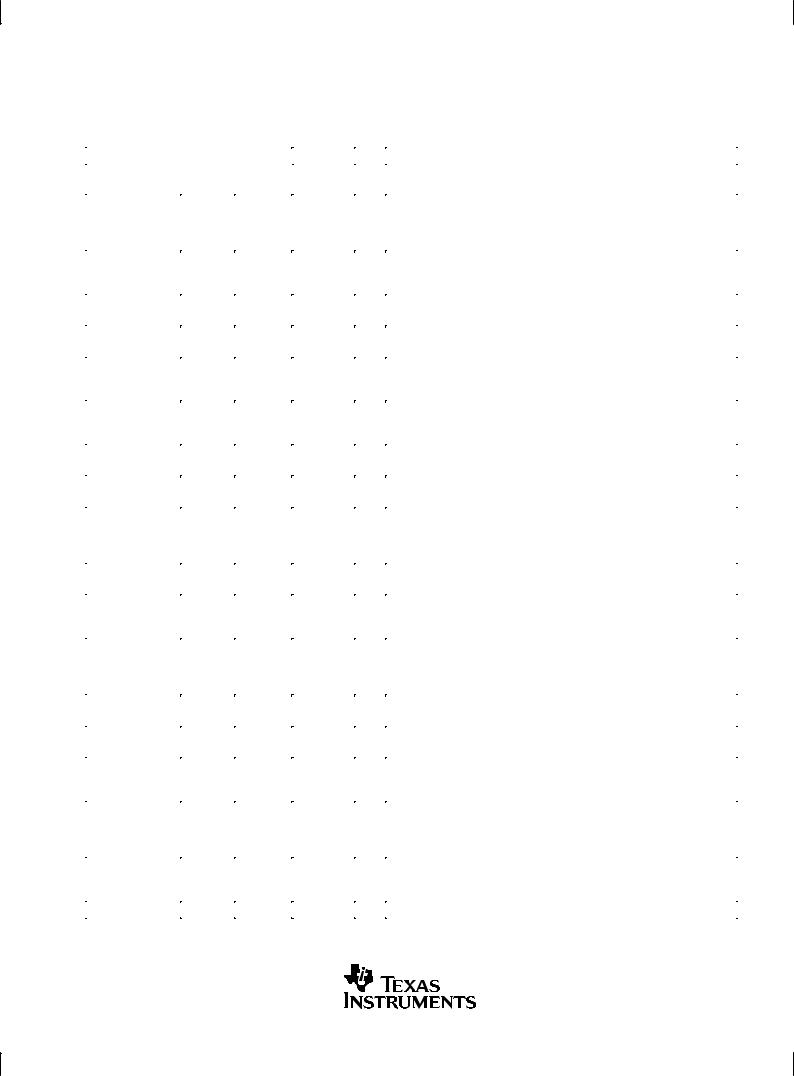
HV PACKAGE (TOP VIEW)
|
NC |
GND |
RPREFIX |
CC |
CC |
GND |
CC |
TI1 |
CC |
NC XI50 |
GND |
NC XI100 |
GND |
OSCSEL |
GND |
|
|
V |
V |
V |
V |
|
|||||||||||
NC |
9 |
8 |
7 |
6 |
5 |
4 |
3 |
2 |
1 |
68 67 66 65 64 63 62 61 |
NC |
|||||
10 |
|
|
|
|
|
|
|
|
|
|
|
|
|
60 |
||
ARB_CLK |
11 |
|
|
|
|
|
|
|
|
|
|
|
|
|
59 |
NC |
PHYENA |
12 |
|
|
|
|
|
|
|
|
|
|
|
|
|
58 |
NC |
VCC |
13 |
|
|
|
|
|
|
|
|
|
|
|
|
|
57 |
NC |
ENA_PRI |
14 |
|
|
|
|
|
|
|
|
|
|
|
|
|
56 |
NC |
VCC |
15 |
|
|
|
|
|
|
|
|
|
|
|
|
|
55 |
RDATA |
N_POR |
16 |
|
|
|
|
|
|
|
|
|
|
|
|
|
54 |
RSTRB |
GND |
17 |
|
|
|
|
|
TSB14C01M |
|
|
|
|
53 |
VCC |
|||
LREQ |
18 |
|
|
|
|
|
|
|
|
|
52 |
TDATA |
||||
VCC |
19 |
|
|
|
|
|
|
|
|
|
|
|
|
|
51 |
TSTRB |
SCLK |
20 |
|
|
|
|
|
|
|
|
|
|
|
|
|
50 |
GND |
TSCLK |
21 |
|
|
|
|
|
|
|
|
|
|
|
|
|
49 |
N_OEB_D |
GND |
22 |
|
|
|
|
|
|
|
|
|
|
|
|
|
48 |
GND |
CTL0 |
23 |
|
|
|
|
|
|
|
|
|
|
|
|
|
47 |
PTEST_INDRV |
CTL1 |
24 |
|
|
|
|
|
|
|
|
|
|
|
|
|
46 |
VCC |
D0 |
25 |
|
|
|
|
|
|
|
|
|
|
|
|
|
45 |
NC |
D1 |
26 |
|
|
|
|
|
|
|
|
|
|
|
|
|
44 |
NC |
|
27 |
28 29 30 31 32 33 34 35 36 37 38 39 40 41 42 43 |
|
|||||||||||||
|
NC |
NC |
CC |
EN EXID |
EN EXPRI |
EX ID5 |
EX ID4 |
EX ID3 |
EX ID2 |
EX ID1 EX ID0 |
GND |
EX PRI3 EX PRI2 |
EX PRI1 |
EX PRI0 |
NC |
|
|
V |
|
||||||||||||||
NC ± No connection
POST OFFICE BOX 655303 •DALLAS, TEXAS 75265 |
3 |

TSB14C01
5-V IEEE 1394-1995 BACKPLANE TRANSCEIVER/ARBITER
SLLS231B ± MARCH 1996 ± REVISED MAY 1997
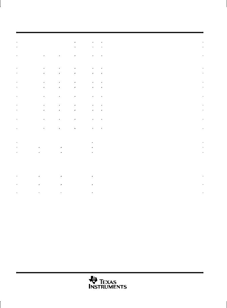
system block diagram
|
|
|
|
|
N_OEB_D |
|
|
|
|
D0 ± D1 |
2 |
|
|
|
|
|
|
/ |
|
|
|
|
|
|
|
|
TSB14C01 |
Tdata |
BPdata |
||
|
|
CTL0 ± CTL1 2 |
|||||
|
1394 Link- |
|
|
|
|
||
Host |
|
/ |
1394 |
Rdata |
|
|
|
Layer |
|
|
|
||||
Interface |
|
|
Backplane |
|
|
|
|
Controller |
|
|
|
|
|
||
|
LREQ |
|
Physical- |
|
|
|
|
|
|
|
Tstrb |
BPstrb |
|
||
|
|
|
|
Layer |
|
||
|
|
|
|
|
|
|
|
|
|
|
|
Controller |
Rstrb |
|
|
|
|
SCLK |
|
|
|
|
|
NOTE A: The backplane transceiver is customer supplied and is different for each type of backplane. |
|
||||||
functional block diagram |
|
|
|
|
|
|
|
|
|
|
|
SCLK |
|
|
|
|
|
|
|
D0, D1 |
Data |
|
|
|
|
|
|
|
|
|
|
|
|
|
|
|
Encode |
|
|
SCLK |
|
|
|
|
|
TxPktStrb |
|
|
|
|
|
|
|
|
|
|
|
Physical ID |
CLK |
|
TxPktData |
|
|
|
|
Pr0 ± Pr3 |
|
|
|
ARB/DATA |
TSTRB |
|
|
|
|
|
|
||
|
2 |
Fair/Urg Req |
|
|
MUX |
TDATA |
|
|
Iso Req |
TxArbStrb |
|
|
|||
D0 ± D1 |
/ |
|
|
||||
Cycle Req |
TxArbData |
|
|
||||
|
2 |
|
|
||||
|
Ack Req |
|
|
|
|
||
CTL0 ± CTL1 |
/ |
|
|
|
|
||
|
|
|
|
|
|
||
LREQ |
|
Arb Won |
ARB |
|
|
LINK/PHY |
Arb Lost |
Control |
|
|
|
|
||
|
|
|
|
|
|
Interface |
Arb Res Gap |
|
|
|
|
|
|
|
|
|
Sub Act Gap |
RxStb |
RSTRB |
|
|
Ack Gap |
RxData |
|
|
|
RDATA |
||
|
|
|
|
|
|
|
Bus Reset |
|
Data |
|
|
|
Resync/ |
|
|
|
CLK |
CLK |
|
CLK |
|
Decode |
||
|
|
|
||
|
|
|
|
|
(see Note A) |
|
|
|
|
|
|
RxData |
|
|
|
|
RxCLK |
RxCLK |
|
NOTE A: CLK is either terminal XI_50 or XI_100 depending on the mode selection.
4 |
POST OFFICE BOX 655303 •DALLAS, TEXAS 75265 |
TSB14C01 5-V IEEE 1394-1995 BACKPLANE TRANSCEIVER/ARBITER
|
|
|
|
|
|
SLLS231B ± MARCH 1996 ± REVISED MAY 1997 |
|
|
|
|
|
|
|
|
|
|
|
|
|
Terminal Functions |
|||
|
|
|
|
|
|
|
|
TERMINAL |
|
|
|
|
|
|
|
NAME |
PM |
HV |
TYPE |
|
I/O |
DESCRIPTION |
|
|
NO. |
NO. |
|
|
|
|
|
|
|
|
|
|
|
|
|
ARB_CLK |
1 |
11 |
TTL |
|
O |
Arbitration clock. ARB_CLK is the clock used for arbitration. ARB_CLK is |
|
|
|
|
|
|
|
for test and debug. It can be put into a high-impedance state by |
|
|
|
|
|
|
|
PTEST_INDRV. This terminal is not used in normal operation and is |
|
|
|
|
|
|
|
always at 49.152 MHz. |
|
|
|
|
|
|
|
|
|
CTL0, CTL1 |
13, 14 |
23, 24 |
TTL |
|
I/O |
Control I/O. These are bidirectional signals that communicate between the |
|
|
|
|
|
|
|
TSB14C01 and the link that control passage of information between the |
|
|
|
|
|
|
|
two devices. |
|
|
|
|
|
|
|
|
|
D0, D1 |
15, 16 |
25, 26 |
TTL |
|
I/O |
Data I/O. These are bidirectional information signals that communicate |
|
|
|
|
|
|
|
between the TSB14C01 and the link. |
|
|
|
|
|
|
|
|
|
ENA_PRI |
4 |
14 |
TTL |
|
I |
Enable priority. ENA_PRI is tied low to enable the 7-bit bus request. See |
|
|
|
|
|
|
|
Table 1 for more information. |
|
|
|
|
|
|
|
|
|
EN_EXID |
18 |
30 |
TTL |
|
I |
Enable external ID. When EN_EXID is asserted high, the ID for this node |
|
|
|
|
|
|
|
is set externally by EX_ID. When this terminal is tied/driven low, the |
|
|
|
|
|
|
|
source of the ID comes from the internal ID register. |
|
|
|
|
|
|
|
|
|
EN_EXPRI |
19 |
31 |
TTL |
|
I |
Enable external priority. When EN_EXPRI is asserted high (external |
|
|
|
|
|
|
|
priority enabled) the priority level for this node is set externally (see |
|
|
|
|
|
|
|
Table 1). This terminal should be tied low when not used. |
|
|
|
|
|
|
|
|
|
EX_ID5 ± EX_ID0 |
20,21,22, |
32,33,34, |
TTL |
|
I |
External ID. The ID for this node is determined by the value on the EX_ID |
|
|
23,24,25 |
35,36,37 |
|
|
|
terminals. Bit 0 is the MSB. |
|
|
|
|
|
|
|
|
|
EX_PRI3 ± |
27,28, |
39,40, |
TTL |
|
I |
External priority. The priority for this node is determined by the values on |
|
EX_PRI0 |
29,30 |
41,42 |
|
|
|
the EX_PRI terminals. See Table 1 for more information. |
|
|
|
|
|
|
|
|
|
GND |
7,12,26, |
4,8,17, |
Supply |
|
Ð |
Circuit ground |
|
|
36,38,49, |
22,38,48, |
|
|
|
|
|
|
51,54,60, |
50,61,63, |
|
|
|
|
|
|
64 |
66 |
|
|
|
|
|
|
|
|
|
|
|
|
|
LREQ |
8 |
18 |
TTL |
|
I |
Link request input. LREQ is an input from the link used by the link to |
|
|
|
|
|
|
|
signal the TSB14C01 of a request to perform some service. |
|
|
|
|
|
|
|
|
|
VCC |
3,5,9,17, |
1,3,5,6, |
Supply |
|
Ð |
Circuit power |
|
|
34,41,57, |
13,15,19, |
|
|
|
|
|
|
59,61,62 |
29,46,53 |
|
|
|
|
|
|
|
|
|
|
|
|
|
NC |
31,32,33, |
9,10,27, |
Ð |
|
Ð |
Not connected. These terminals must be left floating. |
|
|
44,45,46, |
28,43±45, |
|
|
|
|
|
|
47,48,53, |
56±60, |
|
|
|
|
|
|
56 |
65,68 |
|
|
|
|
|
|
|
|
|
|
|
|
|
N_OEB_D |
37 |
49 |
TTL |
|
O |
External driver enable. N_OEB_D is a negative active signal that enables |
|
|
|
|
|
|
|
the external driver for TDATA and TSTRB. |
|
|
|
|
|
|
|
|
|
N_POR |
6 |
16 |
TTL |
|
I |
Logic reset input . Forcing N_POR low causes a reset condition and |
|
|
|
|
|
|
|
resets the internal logic to the reset start state. |
|
|
|
|
|
|
|
|
|
OSC_SEL |
50 |
62 |
VCC / |
|
I |
Select clock frequency. OSC_SEL should be pulled up to VCC when the |
|
|
|
|
GND |
|
|
operating frequency is 50 MHz. When the operating frequency is 100 MHz |
|
|
|
|
|
|
|
then it should be pulled to ground. It should not be left floating. |
|
PHYENA |
2 |
12 |
TTL |
|
O |
Phy enable. When the phy is driving it is low, PHYENA is the control to the |
|
|
|
|
|
|
|
CTL0, CTL1, D0, and D1 drivers. PHYENA is for test and debug. It can |
|
|
|
|
|
|
|
be put into a high-impedance state by PTEST_INDRV. This terminal is not |
|
|
|
|
|
|
|
used in normal operation. |
|
|
|
|
|
|
|
|
|
PTEST_INDRV |
35 |
47 |
TTL |
|
I |
Test output enable. PTEST_INDRV enables/disables the drivers to the |
|
|
|
|
|
|
|
test terminals ARB_CLK, PHYENA, and RPREFIX. During normal |
|
|
|
|
|
|
|
operation, PTEST_INDRV should be tied to VCC to disable the drivers. |
|
RDATA |
43 |
55 |
TTL |
|
I |
Receive data. Incoming data is received at the data rate. |
|
|
|
|
|
|
|
|
|
|
|
|
|
|
|
|
|
POST OFFICE BOX 655303 •DALLAS, TEXAS 75265 |
5 |
TSB14C01
5-V IEEE 1394-1995 BACKPLANE TRANSCEIVER/ARBITER
SLLS231B ± MARCH 1996 ± REVISED MAY 1997
Terminal Functions (continued)
|
TERMINAL |
|
|
|
|
|
|
NAME |
|
PM |
HV |
TYPE |
I/O |
DESCRIPTION |
|
|
|
NO. |
NO. |
|
|
|
|
|
|
|
|
|
|
|
|
RPREFIX |
|
63 |
7 |
TTL |
O |
Receiver prefix. When asserted high (enabled), RPREFIX alerts the |
|
|
|
|
|
|
|
receiver of an incoming packet. RPREFIX is for test and debug and is not |
|
|
|
|
|
|
|
used in normal operation. |
|
|
|
|
|
|
|
|
|
RSTRB |
|
42 |
54 |
TTL |
I |
Receive strobe. RSTRB decodes the received data. |
|
|
|
|
|
|
|
|
|
SCLK |
|
10 |
20 |
TTL |
O |
System clock output. A 49.152-MHz or 24.576-MHz clock signal |
|
|
|
|
|
|
|
synchronized with the data transfers, and provided to the link. |
|
|
|
|
|
|
|
|
|
TDATA |
|
40 |
52 |
CMOS |
O |
Transmit data. Data to be transmitted is serialized on TDATA. |
|
|
|
|
|
|
|
|
|
TI1 |
|
58 |
2 |
TTL |
I |
Test input 1. TI1 is used for test purposes only and should be tied to |
|
|
|
|
|
|
|
ground for normal operation. |
|
|
|
|
|
|
|
|
|
TSCLK |
|
11 |
21 |
TTL |
O |
System clock output. A 49.152-MHz or 24.576-MHz clock signal that is 180 |
|
|
|
|
|
|
|
degrees out of phase with SCLK; it is available if needed. |
|
|
|
|
|
|
|
|
|
TSTRB |
|
39 |
51 |
CMOS |
O |
Transmit strobe. TSTRB encodes transmit data. |
|
|
|
|
|
|
|
|
|
XI_50 |
|
55 |
67 |
CMOS |
I |
External oscillator input. An external 49.152-MHz oscillator can drive the |
|
|
|
|
|
|
|
TSB14C01. |
|
|
|
|
|
|
|
|
|
XI_100 |
|
52 |
64 |
CMOS |
I |
External oscillator input. An external 98.304-MHz oscillator can drive the |
|
|
|
|
|
|
|
TSB14C01. |
|
|
|
|
|
|
|
|
|
|
|
Table 1. External Priority Coding |
||
|
|
|
|
|
EXTERNAL PRIORITY TERMINALS |
DESCRIPTION |
|||
|
|
|
||
ENA_PRI |
EN_EXPRI |
EX_PRI0 ± EX_PRI3 |
||
|
||||
|
|
|
|
|
|
|
L L L L |
|
|
|
|
L L L H |
|
|
X |
H |
. |
The priority for this node is determined by the values on EX_PRI0 ± EX_PRI3. |
|
. |
The state of ENA_PRI can be either tied to VCC or GND. |
|||
|
|
|||
|
|
. |
|
|
|
|
H H H H |
|
|
|
|
|
|
|
L |
L |
X |
This sets a 7-bit bus request and is the cable environment format. Priority must be |
|
|
|
|
set by executing a write request (see Table 10). |
|
|
|
|
|
|
H |
L |
X |
This sets an 11-bit bus request and is the backplane environment format. Priority |
|
|
|
|
is dynamically set as part of the bus request (see Table 8) |
|
6 |
POST OFFICE BOX 655303 •DALLAS, TEXAS 75265 |
TSB14C01 5-V IEEE 1394-1995 BACKPLANE TRANSCEIVER/ARBITER
SLLS231B ± MARCH 1996 ± REVISED MAY 1997
absolute maximum ratings over operating free-air temperature range (unless otherwise noted)²
Supply voltage range, VCC . . . . . . . . . . . . . . . . . . . . . . . . . . . . . . . . . . . . . . . . . . . . . . . . . . . . . . . . . ±0.5 V to 6.0 V Input voltage range, VI . . . . . . . . . . . . . . . . . . . . . . . . . . . . . . . . . . . . . . . . . . . . . . . . . . . . . . ±0.5 V to VCC + 0.5 V Output voltage range at any output, VO . . . . . . . . . . . . . . . . . . . . . . . . . . . . . . . . . . . . . . . ±0.5 V to VCC + 0.5 V Continuous total power dissipation . . . . . . . . . . . . . . . . . . . . . . . . . . . . . . . . . . . . . . See Dissipation Rating Table
Operating free air temperature, TA: TSB14C01 . . . . . . . . . . . . . . . . . . . . . . . . . . . . . . . . . . . . . . . . . . 0°C to 70°C TSB14C01M . . . . . . . . . . . . . . . . . . . . . . . . . . . . . . . . . . . . . . ±55°C to 125°C
Storage temperature range, Tstg . . . . . . . . . . . . . . . . . . . . . . . . . . . . . . . . . . . . . . . . . . . . . . . . . . . . ±65°C to 150°C Lead temperature 1,6 mm (1/16 inch) from case for 10 seconds . . . . . . . . . . . . . . . . . . . . . . . . . . . . . . . . 300°C
²Stresses beyond those listed under ªabsolute maximum ratingsº may cause permanent damage to the device. These are stress ratings only, and functional operation of the device at these or any other conditions beyond those indicated under ªrecommended operating conditionsº is not implied. Exposure to absolute-maximum-rated conditions for extended periods may affect device reliability.
DISSIPATION RATING TABLE
|
T ≤ 25°C |
DERATING FACTOR³ |
T = 70°C |
T = 125°C |
|
PACKAGE |
A |
ABOVE TA = 25°C |
A |
A |
|
POWER RATING |
POWER RATING |
POWER RATING |
|||
|
|||||
HV |
1689 mW |
13.5 mW/°C |
1081 mW |
337 mW |
|
|
|
|
|
|
|
PM |
1350 mW |
10.8 mW/°C |
864 mW |
Ð |
³This is the inverse of the traditional junction-to-ambient thermal resistance (RθJA) and uses a board-mounted RθJA of 92.5°C/W for the PM package and 74°C/W for the HV package.
recommended operating conditions
|
|
MIN |
NOM |
|
MAX |
UNIT |
|
|
|
|
|
|
|
Supply voltage, VCC |
|
4.5 |
5 |
5.25 |
V |
|
High-level input voltage, VIH |
CMOS inputs |
0.7 VCC |
|
|
|
V |
TTL input |
2 |
|
|
VCC |
V |
|
|
|
|
||||
Low-level input voltage, VIL |
CMOS inputs |
0 |
|
|
0.2 VCC |
V |
TTL input |
0 |
|
|
0.8 |
V |
|
|
|
|
||||
|
|
|
|
|
|
|
Input voltage, VI |
CMOS/TTL |
0 |
|
|
VCC |
V |
High-level output current, IOH |
CMOS Drivers |
|
|
|
12 |
mA |
|
|
|
|
|
||
TTL Drivers |
|
|
|
8 |
||
|
|
|
|
|
||
|
|
|
|
|
|
|
Low-level output current, IOL |
CMOS Drivers |
|
|
|
24 |
mA |
|
|
|
|
|
||
TTL Drivers |
|
|
|
8 |
||
|
|
|
|
|
||
|
|
|
|
|
|
|
POST OFFICE BOX 655303 •DALLAS, TEXAS 75265 |
7 |
TSB14C01
5-V IEEE 1394-1995 BACKPLANE TRANSCEIVER/ARBITER
SLLS231B ± MARCH 1996 ± REVISED MAY 1997
electrical characteristics over recommended ranges of operating conditions (unless otherwise noted)
device
|
PARAMETER |
TEST CONDITIONS |
MIN |
TYP |
|
MAX |
UNIT |
|
|
|
|
|
|
|
|
|
|
VOH |
High-level output voltage |
IOH = max, |
VCC = min |
VCC± 0.8 |
|
|
|
V |
VOL |
Low-level output voltage |
IOL = min, |
VCC = max |
|
|
|
0.5 |
V |
|
Input current |
VI = VCC or 0 |
|
|
|
|
± 1 |
μA |
IOZ |
Off-state output current |
VI = VCC or 0 |
|
|
|
|
± 10 |
μA |
thermal characteristics
|
PARAMETER |
TEST CONDITION |
MIN |
|
TYP |
MAX |
UNIT |
|
|
|
|
|
|
|
|
|
|
RθJA |
Junction-to-free-air thermal resistance |
TSB14C01 |
Board mounted, No air flow |
|
|
83 |
|
°C/W |
|
|
|
|
|
|
|||
TSB14C01M |
|
|
74 |
|
°C/W |
|||
|
|
|
|
|
|
|||
|
|
|
|
|
|
|
|
|
RθJC |
Junction-to-case thermal resistance |
TSB14C01 |
|
|
|
16 |
|
°C/W |
|
|
|
|
|
|
|
||
TSB14C01M |
|
|
|
3 |
|
°C/W |
||
|
|
|
|
|
|
|||
|
|
|
|
|
|
|
|
|
switching characteristics, VCC = 5 V, TA = 25°C (See Note 1)
|
PARAMETER |
MEASURED |
TEST CONDITION |
MIN |
|
TYP |
MAX |
UNIT |
|
|
|
|
|
|
|
|
|
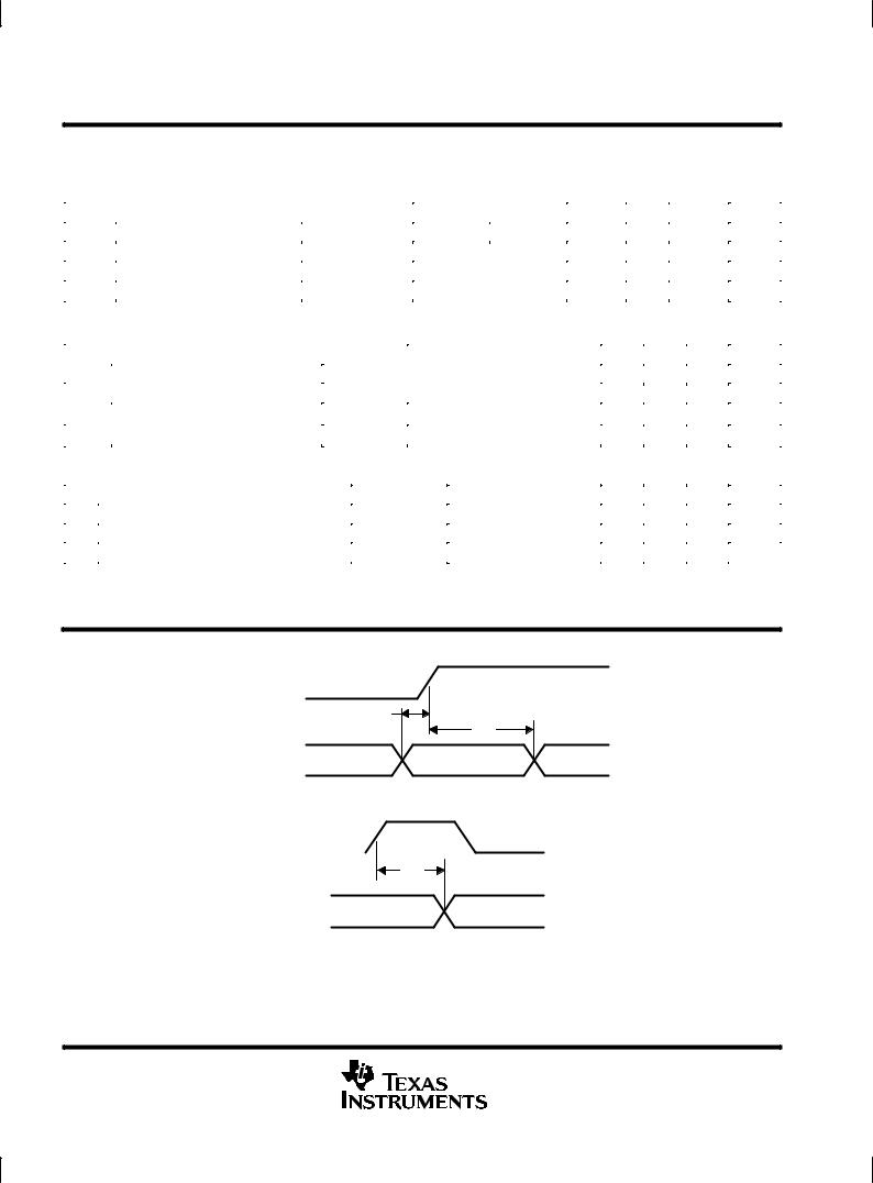
tsu |
D, CTL, LREQ low or high before SCLK high |
50% to 50% |
See Figure 1 |
7 |
|
|
|
ns |
th |
D, CTL, LREQ low or high after SCLK high |
50% to 50% |
See Figure 1 |
1 |
|
|
|
ns |
td |
Delay time, SCLK high to D, CTL high or low |
50% to 50% |
See Figure 2 |
|
|
|
10 |
ns |
NOTE 1: These parameters are ensured by design and are not production tested.
PARAMETER MEASUREMENT INFORMATION
SCLK |
|
|
50% |
|
|
tsu
th
D, CTL, LREQ
Figure 1. D, CTL, LREQ Input Setup and Hold Timing Waveforms
SCLK |
|
|
|
50% |
|
|
|
|
|
|
|
td
D, CTL
Figure 2. D, CTL Output Delay Relative to SCLK Timing Waveforms
8 |
POST OFFICE BOX 655303 •DALLAS, TEXAS 75265 |
TSB14C01 5-V IEEE 1394-1995 BACKPLANE TRANSCEIVER/ARBITER
SLLS231B ± MARCH 1996 ± REVISED MAY 1997
APPLICATION INFORMATION
internal register configuration
The accessible internal registers of this device are listed in Table 2. Bit field descriptions for the registers are given in Table 3.
Table 2. Format for Registers
ADDRESS |
0 |
1 |
2 |
3 |
4 |
5 |
6 |
7 |
|
|
|
|
|
|
|
|
|
0000 |
Physical |
Physical |
Physical |
Physical |
Physical |
Physical |
Reserved |
Reserved |
|
ID[0] |
ID[1] |
ID[2] |
ID[3] |
ID[4] |
ID[5] |
|
|
|
|
|
|
|
|
|
|
|
0001 |
INHB |
IBR |
|
|
RESERVED |
|
|
|
|
|
|
|
|
|
|
|
|
0011 |
|
|
|
RESERVED |
|
|
|
|
|
|
|
|
|
|
|
|
|
0100 |
Priority |
Priority |
Priority |
Priority |
|
RESERVED |
|
|
|
level[0] |
level[1] |
level[2] |
level[3] |
|
|
||
|
|
|
|
|
||||
|
|
|
|
|
|
|
|
|
|
|
|
Table 3. Register Bit Field Key |
|
|
|
|
FIELD |
SIZE |
TYPE |
DESCRIPTION |
|
(Bits) |
|
|
|
|
|
|
Physical ID |
6 |
Read/Write |
Physical identification. Physical ID is the address of the local node and is set to zero on power up. |
|
|
|
|
INHB |
1 |
Read/Write |
Inhibit Drivers. INHB is used to turn off the drivers to TDATA and TSTRB. |
|
|
|
|
IBR |
1 |
Read/Write |
Initiate Bus Reset. IBR is turned on by the link and turned off by the phy when reset is complete. |
|
|
|
|
Priority |
4 |
Read/Write |
Priority setting. The four bits contain the priority of the local node. A higher value in this field |
|
|
|
indicates a higher priority. |
|
|
|
|
transceiver selection
The system designer must select transceivers appropriate to the system requirements to be used with the TSB14C01 and the link layer selected. The following lists requirements for the transceivers needed.
DThe transceivers used must be appropriate to the backplane technology used.
The various backplane technologies require different electrical characteristics in their backplanes. For example BTL uses an operating voltage on the backplane of 2.1 V and a characteristic impedance of 33 Ω while GTL uses an operating voltage of 1.2 V and a characteristic impedance of 50 Ω (see GTL/BTL a Low Swing Solution for High-Speed Digital Logic, TI literature number SCEA003). When a backplane is designed to use BTL technology, then it would be appropriate to also use that technology for the two lines dedicated to the 1394 serial bus. The drivers selected also must be able to supply the current required for the expected backplane loading. For example, BTL operates correctly for a FutureBus configuration backplane at 50 Mbits/s or for a limited number of nodes in a custom configuration at 100 Mbits/s. See the GTL/BTL a Low Swing Solution for High-Speed Digital Logic, TI literature number SCEA003 or the documentation for the transceiver being considered.
DThe transceivers used must assert logic states on the backplane in an appropriate manner for the 1394 backplane arbitration.
Arbitration under 1394 backplane rules requires the drivers to assert the bus to indicate a logical 1 state, that is a logic 1 being driven by the TSB14C01. Conversely, the drivers should release the bus to indicate a logic 0 state, a logic 0 being driven by the TSB14C01. In other words, all drivers must operate in a Wired-OR mode during arbitration.
DThe transceivers used must be able to monitor the bus and drive the bus at the same time.
POST OFFICE BOX 655303 •DALLAS, TEXAS 75265 |
9 |
TSB14C01
5-V IEEE 1394-1995 BACKPLANE TRANSCEIVER/ARBITER
SLLS231B ± MARCH 1996 ± REVISED MAY 1997
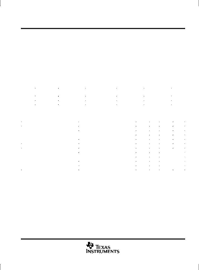
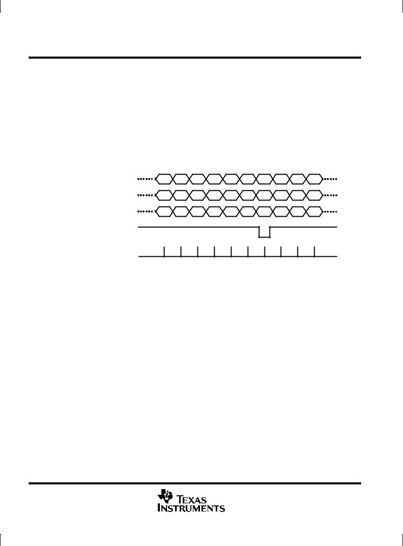
During arbitration, each node that is arbitrating for the bus drives its code then its node number out onto the bus. During each bit period, each node reads back what has been placed on the bus. If it reads back the same data it was sending, the arbitrating node stays in contention for winning the bus. If it reads something different then what it was driving, the arbitrating node loses the bus and drops out of contention. This is the reason for requiring Wired-OR operation during arbitration. As long as each node is still sending 0s onto the bus during arbitration, all nodes are still contending to win the bus. The node with the highest priority (or if all priorities were zero then the highest node number) is the first to drive a 1 onto the bus during arbitration. The node that sends the first 1 (asserting the bus) and reads it back wins the bus. All other nodes read back a 1, which does not match the 0 (releasing the bus) they are sending, and drop out of contention. This arbitration process requires the transceiver selected to be able to read from the bus at the same time it is driving the bus.
For example, if three nodes, each with priority 0 and a node identifiers of 8, 7, and 2, were to arbitrate for the bus the following would occur:
Driven by Node #2 |
0 |
0 |
0 |
0 |
0 |
0 |
0 |
0 |
0 |
0 |
|
(TSB14C01) |
|||||||||||
|
|
|
|
|
|
|
|
|
|
||
Driven by Node #7 |
0 |
0 |
0 |
0 |
0 |
0 |
0 |
0 |
0 |
0 |
|
(TSB14C01) |
|||||||||||
|
|
|
|
|
|
|
|
|
|
||
Driven by Node #8 |
0 |
0 |
0 |
0 |
0 |
0 |
1 |
0 |
0 |
0 |
|
(TSB14C01) |
|||||||||||
|
|
|
|
|
|
|
|
|
|
Bus Data Line (voltage level on the bus)
Bus Read
NOTE A: This bus is reverse logic, a 1 being driven by the TSB14C01 is asserted by driving a 0 onto the bus by the transceiver.
Figure 3. Three Nodes Arbitrating for the Bus
Since the highest node number is 8 (1000b), node 8 outputs the first 1 (assert the bus) and wins the arbitration. The other nodes drop out and do not try to drive their node number onto the bus.
DThe transceivers used must be appropriate for the transfer speed required.
The 1394 bus has two data lines that use Data-Strobe Encoding on the bus. This requires that the transceivers be able to operate at a maximum frequency of one half of the maximum data transfer rate. When operating at 50 Mbits/s, the maximum frequency the drivers are required to operate at is 25 MHz. When operating at 100 Mbits/s, the maximum frequency the drivers are required to operate at is 50 MHz.
10 |
POST OFFICE BOX 655303 •DALLAS, TEXAS 75265 |
 Loading...