


UC3730QTR
Texas Instruments UC3730QTR, UC3730T, UC3730Q, UC3730N, UC2730T Datasheet
...
Thermal Monitor
UC1730
UC2730
UC3730
DESCRIPTION
The UC1730 family of integrated circuit devices are designed to be used in
a number of thermal monitoring applications. Each IC combines a tempera-
ture transducer, precision reference, and temperature comparator allowing
the device to respond with a logic output if temperatures exceed a user pro-
grammed level. The refe rence on these devices is capable of supplying in
excess of 250mA of output current − by setting a l evel o f power dissipation
the rise in die temperature will vary with airflow past the package, allowing
the IC to respond to airflow conditions
These devices come in an 8-Pin DIP, plastic or ceramic, a 5-Pin TO-220 or a
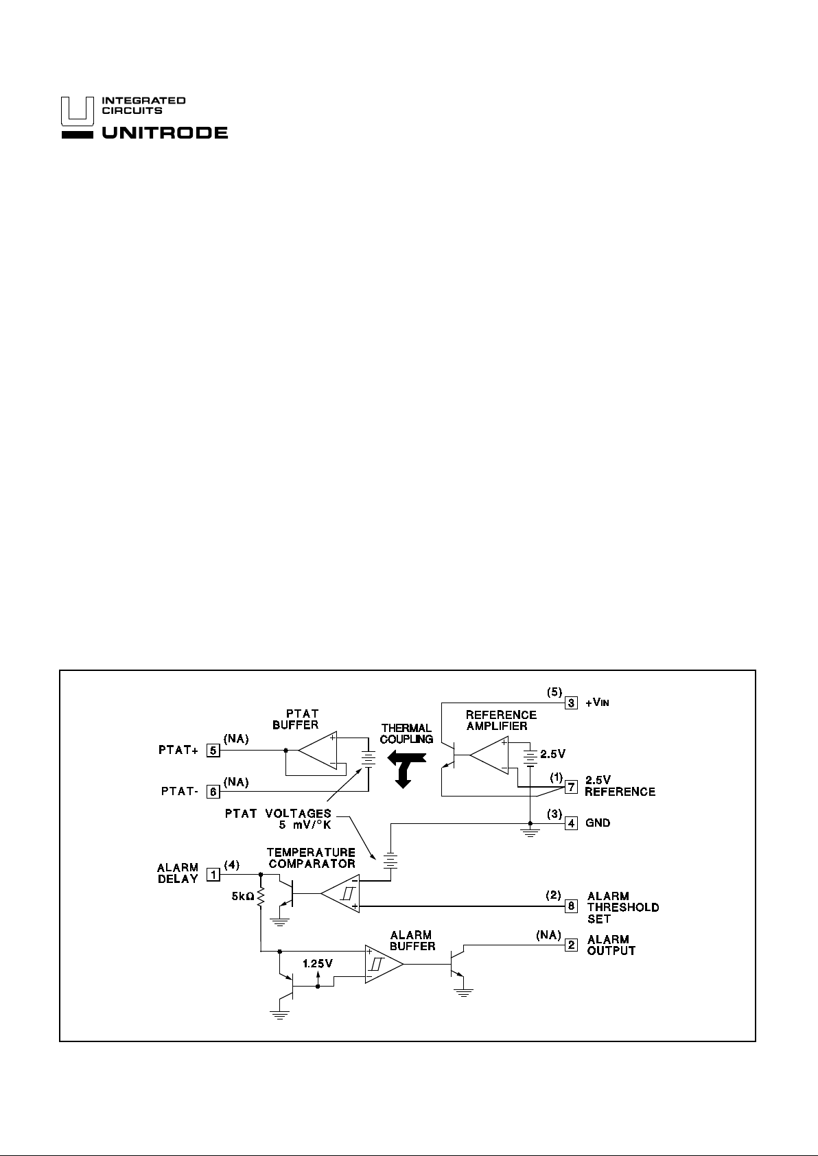
PLCC-20 version. In the 8-Pin version, a PTAT (proportional to absolute
temperature) output reports die tempe rature directly. This output is config-
ured such that its output level can be easily scaled up with two external gain
resistors. A second PTAT source is internal ly refere nced to the temperature
comparator. The other input to this comparator can then be externally pro-
grammed to set a temperature threshold. When this temperature threshold
is exceeded an alarm delay output is activated. Following the activation of
the delay output, a separa te open colle ctor output is turn ed on. The delay
pin can be programmed with an external RC to provide a time separation
between activation of the del ay pin and the alarm pin, p ermitting shutdown
diagnostics in applications where the open collector outputs of multiple parts
are wire OR’ed together .
The 5-Pin version in the TO-220 package is well suited for monitoring
heatsink temperatures. Enha nced airfl ow sensiti vities can be obtained with
this package by mou nting the device to a small heatsink in the airstream.
This version of the device does not include the PTAT output or the open col-
lector alarm output.
FEATURES
• On-Chip Temperature Trans ducer
• Temperature Comparator Gives
Threshold Temperature Alarm
• Power Reference Permits Airflow
Diagnostics
• Precision 2.5V Power Reference
Permits Airflow Diagnostics
• Transducer Output is Easily Scaled
for Increased Sensitivity
• Low 2.5mA Quiescent Current
BLOCK DIAGRAM
10/94
Pin numbers shown for 8-Pin DIP, ( ) number for 5-Pin TO-22 0.
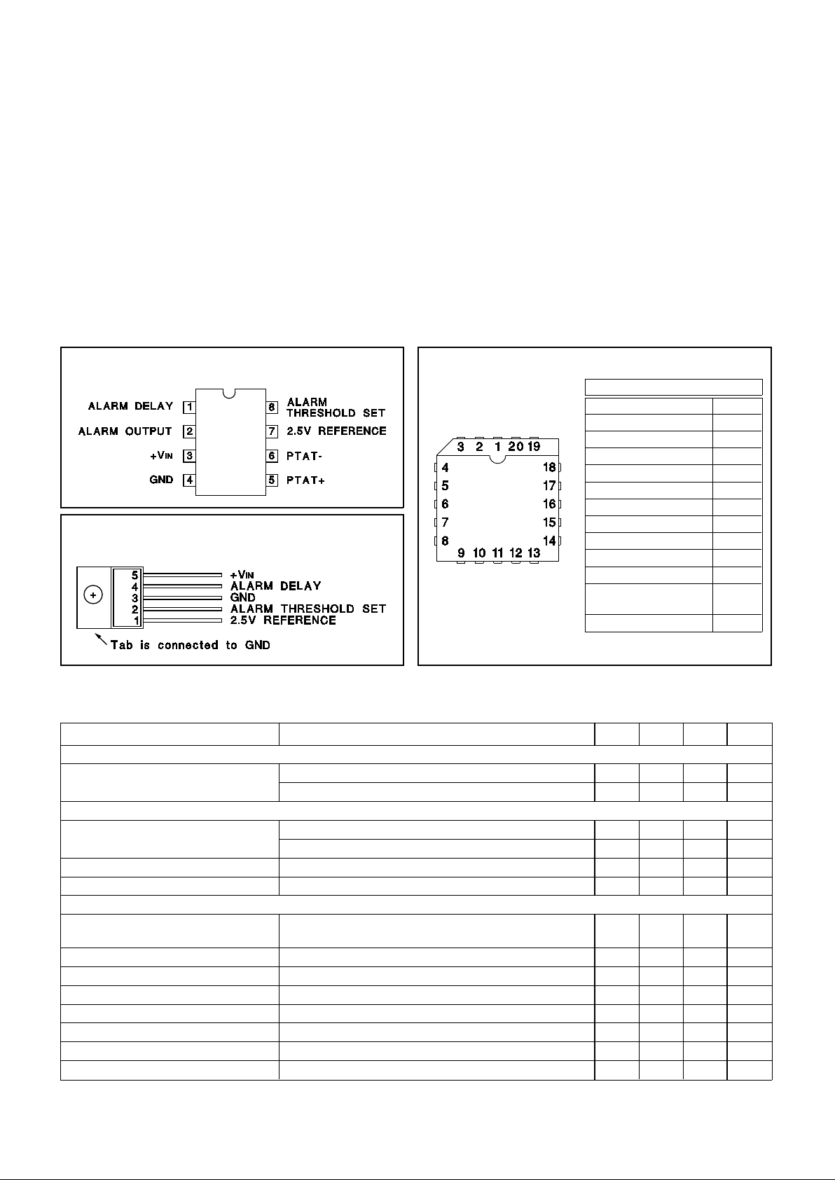
PACKAGE PIN FUNCTION
FUNCTION PIN
N/C 1-3
ALARM DELAY 4
ALARM OUTPUT 5
+V
IN 6
GND 7
N/C 8-13
PTAT+ 14
PTAT- 15
2.5V REFERENCE 16
2.5V REFERENCE 17
ALARM
THRESHOLD SET
18
N/C 19-20
Input Supply Voltage, (+VIN). . . . . . . . . . . . . . . . . . . . . . . 40V
Alarm Output Voltag e (8-Pin Vers ion Only). . . . . . . . . . . 40V
Alarm Delay Voltage. . . . . . . . . . . . . . . . . . . . . . . . . . . . . 10V
Alarm Threshold Set Voltage . . . . . . . . . . . . . . . . . . . . . . 10V
2.5V Reference Output Current . . . . . . . . . . . . . . . . . -400 mA
Alarm Output Current (8-Pin Vers io n Only) . . . . . . . . . . 0 mA
Power Dissipation at T
A = 25 °C (N ote 2) . . . . . . . . . 1000 mW
Power Dissipation at T
C = 25°C (Note 2). . . . . . . . . 200 0 m W
Therma l Resis ta nce Ju nct ion to Amb ie nt
N, 8-Pin Plastic DI P . . . . . . . . . . . . . . . . . . . . . . . . . 110°C/W
J, 8-Pin Ceramic DIP . . . . . . . . . . . . . . . . . . . . . . . . 110°C/W
T, 5-Pin Plastic DIP TO- 220 . . . . . . . . . . . . . . . . . . . . 65°C/W
Thermal Resis tance Ju nct ion to Case
N, 8-Pin Plastic DI P. . . . . . . . . . . . . . . . . . . . . . . . . . . 60°C/W
J, 8-Pin Ceramic DIP. . . . . . . . . . . . . . . . . . . . . . . . . . 40°C/W
T, 5-Pin Plastic TO -22 0. . . . . . . . . . . . . . . . . . . . . . . . . 5°C/W
Operating Junct ion Te mp era tu re . . . . . . . . . -55°C to +150°C
Storage Temperature . . . . . . . . . . . . . . . . . . -65°C to +150°C
Lead Tempera tu re (Solderin g, 10 Seconds). . . . . . . . . 300°C
Note 1: Voltage s are refer ence d to grou nd. Current s are posi-
tive into, negative out of, the specified terminals.
Note 2: Consult Packaging sectio n of Data book for therma l
limitations and con sider atio ns of pack age.
DIL-8 (TOP VIEW)
N or J Package
5-PIN TO-220 (TOP VIEW)
T Package
UC1730
UC2730
UC3730
CONNECTION DIAGRAMS
PLCC-20 (TOP VIEW)
Q Package
ABSOLUTE MAXI MUM RATING S
ELECTRICAL CHARACTERISTICS:
PARAMETERS TEST CONDITIONS MIN TYP MAX UNITS
INPUT SUPPLY
Supply Current +V
IN = 35V 2.8 4.0 mA
+V
IN = 5V 2.3 3.5 mA
REFERENCE
Output Volt age TJ = 25°C 2.475 2.5 2.525 V
Over Temperature 2.46 2.54 V
Load Regulation I
OUT = 0 to 250mA 8.0 25 mV
Line Regulation +V
IN = 5 to 25V 1.0 5.0 mV
TEMPERATURE COMPARATOR
Temperature Com par ator Thre shold at 300°K (26.85°C), Nominally 5m V/ °K,
V
INPUT High to Low
1.475 1.50 1.525 V
Tempe rat ure Error -10 10 °C
Threshold Line Regula tion +V
IN = 5 to 25V 0.005 0 .0 2 %/V
Temperature Linearit y Note 2 2.0 5.0 °C
Threshold Hyster esis 3.0 8.0 15 mV
Input Bias Cur ren t V
INPUT at 1.5V -0.5 -0.1 µA
Max Output Current VOUT = 1V 1.2 3.0 mA
Output Sat Volta ge I
OUT = 100µA 0.05 0.25 V
Unless otherw ise stat ed, these sp ecif icat io ns apply for TJ = 0°C to +100°C f or the
UC3730, -25°C to + 100°C for the UC2730 and -55°C to +125°C for the UC1730,
+VIN = + 5V, and PTAT– = 0V. TA = TJ.
2
 Loading...