


Remote control
1 |
Standby |
2 |
ZOOM |
3 |
LIST |
4 |
TIMER |
5 |
TEXT |
6 |
MUTE |
7 |
M/P |
8 |
V+ |
9 |
OK |
10 |
CH |
11 |
FAV |
12 |
RECALL |
13 |
PAUSE |
14 |
INFO |
15 |
0–9 |
16 |
P– |
17 |
P+ |
18 |
V– |
19 |
CH |
20 |
MENU |
21 |
EXIT |
22 |
AUDIO |
23 |
EPG |
24 |
TV/SAT |
25 |
TV/RADIO |
Switches on and to the standby mode
Enlarges TV image
Invokes TV channel list
Invokes timer
Invokes Teletext
Turns off sound
Multi-picture function, invokes thumbnail view
Increases volume/cursor moves to the right
In normal mode: invokes current channel list In a menu: confirms menu item
Switches to the next lower channel location/cursor moves down
Invokes own favorite list
Switches to previously selected channel
Stills the frame
Displays reception data of the current channel (satellite-finder function)
Selects channel directly, numerical input
In normal mode: changes channel group
In TV channel list: Ten-key block commutation
In normal mode: changes channel group
In TV channel list: Ten-key block commutation
Decreases volume/cursor moves to the left
Switches to the next higher channel location/cursor moves up
Invokes main menu
Exits menu or menu item
Changes audio mode
Invokes Electronic Programme Guide (if offered by the broadcasting station)
Switches between terrestrial and satellite antenna
Switches between TV and radio mode

Digital Mini Satellite System SL 65/12
Operating manual
Version 1.0 GB, as of 09/01/2007
Modifications and errors reserved.
We do not assume any liability for printing errors.
Dear customer,
Having in mind an environmentally friendly behaviour we ask you to switch off your receiver after usage.
With this, you will contribute to the protection of the environment and save money.
2

Preface
Preface
This operating manual will help you in the
•appropriate
•safe
usage of the digital mini satellite system SL 65/12, hereafter called the “satellite system” in short.
The satellite system is packed in a transport case and consists of:
•a digital satellite receiver SL 65/12 (receiver unit), hereafter called the receiver in short and
•the antenna unit with installation material.
We assume that users of the satellite system have overall knowledge regarding handling audio and video equipment.
Every person who
•installs,
•connects,
•operates,
•cleans
•disposes of
this satellite system must be familiar with the entire content of this operating manual. Always keep this operating manual in the proximity of the satellite system.
Style features
Specific style features have been given in different sections of the operating manual. Thus, you can easily differentiate whether it concerns
normal text,
• enumerations oractions.
3
|
Contents |
Contents |
|
Preface ............................................................................................... |
3 |
Style features .................................................................................... |
3 |
Contents ............................................................................................ |
4 |
Safety instructions ........................................................................... |
7 |
Basic safety instructions......................................................... |
7 |
Appropriate use .............................................................................. |
10 |
Scope of supply .............................................................................. |
12 |
Description ...................................................................................... |
14 |
Quick guide ..................................................................................... |
18 |
Antenna installation ....................................................................... |
19 |
Installation of the antenna ............................................................. |
19 |
Installation options......................................................................... |
22 |
Receiver connection....................................................................... |
31 |
LNB cable installation .................................................................... |
32 |
Connection with the Scart cable ................................................... |
34 |
Connection with the Cinch cable .................................................. |
36 |
Connection of an audio-digital receiver ....................................... |
36 |
Direction of the antenna................................................................. |
38 |
Correct location .............................................................................. |
38 |
Rough direction of the antenna .................................................... |
40 |
Getting started ................................................................................ |
43 |
Remote control ............................................................................... |
43 |
Receiver ........................................................................................... |
44 |
Fine tuning of the antenna............................................................. |
45 |
4

|
Contents |
Operation ......................................................................................... |
48 |
Screen-inlays while switching channels ...................................... |
48 |
User interface on the TV screen.................................................... |
50 |
Menu structure................................................................................ |
51 |
Menu navigation ............................................................................. |
52 |
Channel (symbol: TV)..................................................................... |
53 |
Installation (symbol: Satellite antenna)........................................ |
58 |
System Setup (symbol: gearwheel) .............................................. |
62 |
Tools (symbol: tools) ..................................................................... |
66 |
Software update via satellite ......................................................... |
67 |
Keys with special functions .......................................................... |
68 |
Switch between TV and SAT ......................................................... |
68 |
Switch between TV and radio ........................................................ |
68 |
ZOOM ............................................................................................... |
68 |
LIST .................................................................................................. |
68 |
AUDIO .............................................................................................. |
69 |
EPG .................................................................................................. |
69 |
TEXT................................................................................................. |
69 |
M/P.................................................................................................... |
70 |
MUTE................................................................................................ |
70 |
FAV................................................................................................... |
70 |
RECALL ........................................................................................... |
71 |
INFO - acoustic signal for directing the satellite antenna .......... |
71 |
0 – Sleep timer ................................................................................ |
71 |
PAUSE.............................................................................................. |
71 |
Dismantling the satellite system ................................................... |
72 |
Cleaning........................................................................................... |
73 |
Maintenance .................................................................................... |
73 |
Tips and tricks/Trouble shooting .................................................. |
74 |
Disposal ........................................................................................... |
77 |
Specifications ................................................................................. |
78 |
Manufacturer ................................................................................... |
80 |
Guarantee ........................................................................................ |
80 |
Declaration of conformity .............................................................. |
81 |
Index................................................................................................. |
82 |
|
5 |

Contents
Glossary .......................................................................................... |
84 |
6

Safety instructions
Safety instructions
Please read the safety instructions carefully before operating the satellite system .
Please follow all warnings and instructions on the equipment and in the operating manual.
 Basic safety instructions
Electrical connection
•Do not expose the receiver to rain or any kind of humidity to avoid risk of fire and electric shock.
•Never open the casing. Otherwise, there is a risk of electric shock.
•Connect the receiver only to the power source installed by an expert. It is either:
- for an external power pack:
a 100–240 V, 50-60 Hz mains socket as per specifications or - for a 12 V cable:
a 11 V – max. 14 V DC supply as per specifications.
•Ensure that the total power consumption by the antenna connection of the receiver does not exceed “LNB IN” 300 mA.
•Pull the external power pack or the 12 V cable out of the mains socket if you will not use the device for a longer period of time. Only pull at the external power pack or at the head piece of the 12 V cable, not at the cable itself.
•In case of a storm, pull the external power pack or the 12 V cable of the receiver out of the mains socket.
•In case of a storm, pull the LNB-cable out of the receiver.
•If foireign bodies or fluids enter the receiver, immediately pull out the external power pack or the 12V cable out of the socket. Ask a qualified person to check the equipment before operating it once again. Otherwise, there is a risk of electric shock.
•Do not bend or crimp any cable.
7

Safety instructions
•If a cable used for mains supply is damaged, the receiver must be repaired by an expert before reusing it. Otherwise, there is a risk of electric shock.
•Never allow children to operate the receiver or to play with the antenna unit unless supervised.
•Always ask qualified personnel to carry out maintenance jobs. Otherwise, you are putting yourself and others at risk.
•Disconnect the receiver from the power source in case of operational disruptions.
•Ensure that the power source is easily accessible.
•Spare parts must be ordered directly from the manufacturer
•Modifications of the device lead to an extinction of the manufacturer’s liability.
•Remove protection film.
Correct position
•Place the receiver on a stable and even base.
•Use the receiver only with adequate climatic conditions.
•Avoid proximity to:
-heat sources, like e. g. heaters,
-naked flames, like e. g. candles,
-devices with strong magnetic fields, like e.g. loudspeakers.
-Never place receptacles filled with liquid (vases) on the receiver.
•Avoid direct sunlight and places with an extremely high amount of dust.
•Never cover ventilation slits. Provide for sufficient ventilation by maintaining a safety distance of 5 cm to other objects.
•Do not place any heavy objects on the receiver.
•Humidity may settle in the receiver if it is brought into hot surroundings from a cold one. In this case, wait for about an hour before operating the equipment.
•Arrange all cables in such a manner that no-one steps or trips over them.
8

Safety instructions
•The antenna unit is not suitable for operating in case of high wind pressures. Do not expose it to strong wind.
Correct battery handling
•Batteries may contain toxic agents. Ensure that batteries are not within the reach of children. Children may eat and swallow batteries.
•Batteries that are getting discharged may damage the remote control. If the receiver is not in use for a longer period of time, remove the batteries from the remote control.
•Batteries may contain toxic agents. Therefore, dispose of the batteries immediately in an ecologically accepted manner according to the prevailing statutory regulations. Never throw the batteries into normal household waste.
•Never expose the batteries to open fire or strong heat, as otherwise there is a danger of explosion.
•Replace the batteries always by batteries of the same type.
Explanation of the safety instructions
The following categories of safety instructions are included in the operating manual:
 Danger!
Instructions with the word DANGER give a warning against possible personal injuries.
 Caution!
Instructions with the word CAUTION give a warning against possible material or environmental damages.
These instructions contain special information for the commercial use of the satellite system.
9

Safety instructions
Appropriate use
The satellite system receives digital satellite channels for private use. It is exclusively meant for this purpose and must only be used for the same. This also includes paying attention to all information contained in these operating instructions, especially the safety instructions.
Due to its user-friendly installation and disassembly, the satellite system is ideal for mobile use (camping or caravans). As there are diverse installation options, the system can be used in many places:
•on/at tables
•at masts
•at walls
•on lawns
•on crates
•etc.
Please observe all prohibitions or information of the local administration (if any).
Please observe the following safety instructions for each kind of installation:
 Danger!
Do not expose the satelite system to high loads due to wind pressures, e.g.
-installation in great heights (balcony railings)
-storm (wind speed > 75 km/h)
In case of non-observance, there is a risk of damage to property and personal injury.
Wind speed |
40 |
50 |
60 |
70 |
80 |
90 |
100 |
110 |
|
(km/h) |
|||||||||
|
|
|
|
|
|
|
|
||
|
|
|
|
|
|
|
|
|
|
Load of the |
|
|
|
|
|
|
|
|
|
antenna due to |
11.27 |
17.64 |
25.48 |
34.59 |
45.28 |
57.23 |
70.66 |
85.55 |
wind pressure (N)
10
Safety instructions
 Caution!
The maximum bending moment of the satellite system is 15.30 Nm. Please make sure during installation that the fixation is able to withstand this pressure.
Do not install the satellite system at places with difficult accessibility. Mount the satellite system only at places at which it will be easily accessible for you without any danger. Make sure that in case of need you will always be able to remove the system.
Any other use is considered to be improper and may lead to material damages and even personal injuries.
Amongst others, information on wind speed is available on the Internet.
Do not leave the satellite system unattended.
COMAG Handels AG does not bear any liability for damages caused due to improper use.
11

Scope of supply
Scope of supply
Check the scope of supply after your purchase.
The receiver, the remote control, the 2 batteries, the external power pack and the 12V cable for the cigarette lighter are included in a box. We recommend packing these pieces again in the box when dismounting the system.
12

Scope of supply
No. |
|
Pieces |
|
Description |
|
|
|
|
|
without |
|
1 |
|
Operating manual |
figure |
|
|
|
|
|
|
|
|
|
1 |
|
1 |
|
Transport box |
|
|
|
|
|
2 |
|
1 |
|
Antenna with base |
|
|
|
|
|
3 |
|
1 |
|
Digital satellite receiver SL 65/12 |
|
|
|
|
|
4 |
|
1 |
|
External power pack |
|
|
|
|
|
5 |
|
2 |
|
Battery for the remote control |
|
|
|
|
|
6 |
|
2 |
|
Wing nut for U bracket |
|
|
|
|
|
7 |
|
2 |
|
Plain washer for U bracket |
|
|
|
|
|
8 |
|
4 |
|
Dowel for wall bracket |
|
|
|
|
|
9 |
|
4 |
|
Screw for wall bracket |
|
|
|
|
|
10 |
|
2 |
|
Lateral rods |
|
|
|
|
|
11 |
|
1 |
|
Single universal LNB |
|
|
|
|
|
12 |
|
1 |
|
LNB-bracket |
|
|
|
|
|
13 |
|
1 |
|
12V cable for cigarette lighter |
|
|
|
|
|
14 |
|
1 |
|
Scart cable |
|
|
|
|
|
15 |
|
2 |
|
F connector |
|
|
|
|
|
16 |
|
1 |
|
10m coaxial cable (not pre-converted) |
|
|
|
|
|
17 |
|
1 |
|
Remote control |
|
|
|
|
|
18 |
|
1 |
|
U bracket |
|
|
|
|
|
13

Description
Description
You can receive uncoded (free-to-air) digital satellite channels with the satellite system without depending on a fix mounted satellite antenna. The mobile antenna allows you to receive signals at different places, like e.g. on a camping site. With the mounting parts, the antenna can be installed e.g. on a balustrade, a mast or a wall. Naturally, you can also connect the receiver to a fix installed satellite antenna.
It is not necessary to set the receiver yet. The most important broadcasting stations and satellites have already been preset.
The following satellites have been preset by the factory:
•Astra 19.2E
•Hotbird 13.0E
•Türksat 42.0E
•Sirius2 5.0E
•Amos/Atlantic4-5W
•Astra 28.2E
•HispaSat 30W
•Eutel W3A 7E
•Eutel W2 16E
•Hellasat 39E
The antenna has to be directed towards the desired satellite.
Please note that the reception of the preset satellites depends on the location. The satellite system has been designed for mobile use. Therefore not at each location all preset satellites can be received due to the size of the antenna. Please compare the elevation table in the section „Rough direction of the antenna“ on page 42.
The receiver will scan for further new broadcasting stations as soon as you initiate the automatic scan of broadcasting stations for this satellite. Satellites not preset may be added.
14

Description
All receiver settings can be done easily using the user interface (menu)) on the TV screen.
The multilingual user interface supports following languages:
•German
•Italian
•Spanish
•Greek
•English
•Polish
•Czech
•Slovak
•Hungarian
•Danish
•French
•Swedish
•Croatian
Further features:
•Software update via satellite ASTRA 19° East or via the RS232 connection on the rear side of the device.
•Short switching time, fast boot process when switching on the receiver
•Saves the channel last watched (Last Station Memory)
•LNB control logic (sound 0/22 kHz), max. current delivery for LNB 300 mA
•Symbol rate 1-35 MS/s and 950-2150 MHz input frequency
•Manual PID entry possible
•3 keys at the frontage
•4-digit LED display
•Plug & play
•External power pack 100–240 V, 50/60 Hz, output 12V; 1.0A
15

Description
•4,500 channel-storage locations
•Parental lock (preset password: 0000)
•1 favorite list and 8 channel groups
•Automatic scan of broadcasting stations
•List editor for broadcasting stations
•Analogue sound output through Cinch connector (stereo), volume adjustment possible via remote control
•Coaxial digital output (digital audio)
•2 Euro-SCART connections for TV and video set
•Video output signal CVBS
•Loop-through-function in standby mode for the connection of an analogue receiver
•Super fast videotext with a memory of 800 pages
•Digital radio reception, background image for radio (background display)
•Additional channel information is displayed when the channel is changed.
•DiSEqC 1.0, 1.2, Go-to X is supported if an appropriate antenna unit is connected
•SWAP function (via Recall key)
•Screen aspect ratios can be set to 4:3, 16:9, and automatically (letterbox)
•Multi-functional timer, 8x and linked with EPG, sleep timer
•Electronic Programme Guide EPG (up to 14 days in advance, channel-dependent)
•SCPC/MCPC reception standard C/Ku-band satellites
•Automatic selection of the TV standard with video converter
•Zoom function
•Multi-picture function
•Digital satellite finder for optical and acoustic adjustment of the antenna
16

Description
A suitable channel editor is additionally available through our service hotline. Then you will be able to edit the channel lists of the receiver using your computer. Please read the information on our website for this purpose.
Please note that under the Web address:
www.mysilvercrest.de
•current software versions (if required)
•and channel-list editing software for the PC
can be downloaded.
Should you have any questions please contact our service hotline.
17

Quick guide
Quick guide
You must install, connect and adjust your satellite system in the following sequence to be able to use it.
Install the antenna.
Connect the receiver to the equipment.
Install the LNB cable.
Connect the LNB cable to the antenna.
Direct the antenna roughly.
Insert the batteries in the remote control.
Connect the receiver and the equipment to the power source and switch them on.
Set the channels using the remote control.
Direct the antenna finely if the reception quality is not satisfactory.
If you would like to do individual settings for the receiver, invoke the user interface on the TV screen.
Make the desired settings in the menus.
18
Antenna installation
Antenna installation
The antenna consists of a few individual components and is simple to install.
Take out the system components from the transport box.
Remove the packing material.
Installation of the antenna
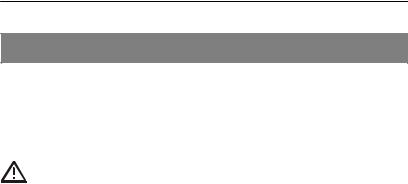
Step 1: Place the antenna with its base on a suitable surface and open it in direction of the arrow until it is in a vertical position.
antenna
Base of antenna
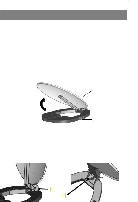
Step 2: Now, the antenna is open. For fixing the angle of inclination of the antenna please tighten both wing nuts (arrow 1). The adjustment of the angle of inclination is described in section “Direction of the antenna“ on page 38. The horizontal direction (azimut) by rotating the antenna wll be fixed with the wing nut at arrow 2.
1
2
19
Antenna installation
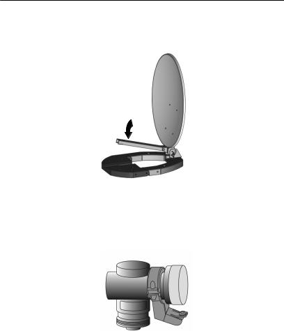
Step 3: Now take the LNB arm down in direction of the arrow until it is locked noticeably.
Step 4a: For installing of the LNB in the LNB bracket untighten the 2 screws of the LNB bracket and remove the top half of the LNB bracket. Then insert the LNB as shown in the picture and fix the top cover again with the screws and nuts. Tighten the screws uniformly.
The indication “TOP“ at the LNB must be in the middle and face upwards.
For step 4a you will need a crosstip screwdriver (not included in the scope of supply). Tighten the screws of the LNB bracket only in such a way that the LNB is fixed. If you tighten them too much, the LNB bracket could break. Additionally, the LNB could be deformed or damaged.
20
Antenna installation
Step 4b: Insert the LNBbracket in direction of the arrow as far as it will go into the LNB arm until the LNB bracket is locked. While you are doing this, press the clip with the button for installation slightly down.
Press button to remove.
Step 5: Now, the antenna is completely installed. Fix the antenna cable at the LNB. The installation of the antenna cable is described in the section “LNB cable installation“ on page 32.
For dismantling the antenna carry out step 1 - 5 in reverse order.
21

Antenna installation
Installation options
The antenna can be set up in different ways using the installation material provided.
For clarification, the installation options are illustrated in the pictures below.. To make the picture less complex the antenna cable is not illustrated here. For a complete installation of the satellite system the cable must be fixed at the LNB.
Please observe all prohibitions or information of the local administration (if any).
When selecting an installation place you should make sure in any case that there are no obstacles between the antenna and the satellite. No tree, house, pane or other obstacles must block visibility.
As a general rule:
an obstacle may only be half the size as its distance to the antenna.
The surface of the mounting position may get damaged slightly for all these installation options. You can protect the sensitive surface from scratches and pressure marks by placing a piece of felt, cardboard or similar on it.
22
Antenna installation
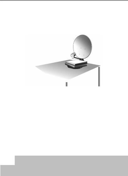
Installation on a table
Place the installed antenna on a table. The base of the antenna must be entirely placed on the table surface.
After the cabling of the satellite system the antenna can be directed to the desired satellite. For this, please proceed as described in the section “Direction of the antenna“ on page 38.
Put sufficient weight on the base, e.g. books, to avoid a tipping over of the antenna by an unintentional external influence (e.g. wind).
The antenna can alternatively be installed at a table leg. For doing this, please proceed as described in the section “Installation on a mast.
Should the table be in a room, make sure to put it near an open window to reach an optimum reception.
 Caution!
You can protect the sensitive surface from scratches and pressure marks by placing a piece of felt, cardboard or similar on it.
23
Antenna installation
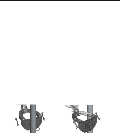
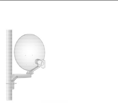
Installation on a mast
First of all, rotate the antenna by 180° so that the LNB will face away from the antenna base.
Now, flap down the antenna base by 90° using the articulation.
Then fix the lateral rods with the wing nuts at the left and right side of the base to get the required stability. The cavities of the lateral rods must face towards the inside of the base. Now. the lateral rods rest directly on the base. The spring ring and the plain washer must be placed between the lateral rods and the wing nuts. Here, the plain washer rests on the respective lateral rod. The spring ring must be placed between the plain washer and the wing nut.
For fixing the base on the mast, place the U bracket around the mast and lead it through the corresponding holes of the base. Now tighten the wing nuts uniformly.
The maximum diameter of the mast must not exceed 60mm.
24
Antenna installation
After the cabling of the satellite system the antenna can be directed to the desired satellite. For this, please proceed as described in the section “Direction of the antenna“ on page 38.
For achieving a safe installation on the mast, please make sure that the plain washers are always placed between the wing nuts of the U bracket and the base.
25
Antenna installation
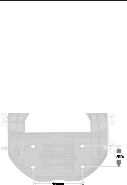
Installation on a wall
First of all, rotate the antenna by 180° so that the LNB will face away from the antenna base.
Now, flap down the antenna base by 90° using the articulation.
Then fix the lateral rods with the wing nuts at the left and right side of the base to get the required stability. The cavities of the lateral rods must face towards the inside of the base. Now, the lateral rods rest directly on the base. The spring ring and the plain washer must be placed between the lateral rods and the wing nuts. Here, the plain washer rests on the respective lateral rod. The spring ring must be placed between the plain washer and the wing nut.
Now, put the base on the place at which it is to be installed and mark the position of the four bore holes. In the picture you can see the holes and the boring distances for the screws:
Drill the four boreholes. The size of the bore holes must correspond to the dowels included in the scope of supply.
26
 Loading...