


NSC 5962R8766401SA, 5962R8766401RA, 5962R87664012A, 5962-8766401SA, 5962-8766401RA Datasheet
...August 1998
54ACT573
Octal Latch with TRI-STATE®
General Description
The 'ACT573 is a high-speed octal latch with buffered com- mon Latch Enable (LE) and buffered common Output Enable (OE) inputs.
The 'ACT573 is functionally identical to the 'ACT373 but has inputs and outputs on opposite sides.
Outputs
Features
nICC and IOZ reduced by 50%
nInputs and outputs on opposite sides of package allowing easy interface with microprocessors
nUseful as input or output port for microprocessors
nFunctionally identical to 'ACT373
nTRI-STATE outputs for bus interfacing
nOutputs source/sink 24 mA
n'ACT573 has TTL-compatible inputs
nStandard Military Drawing (SMD) Ð 'ACT573: 5962-87664
Logic Symbols
IEEE/IEC
DS100332-1
DS100332-2
|
Pin Names |
Description |
|
|
|
|
|
|
D0±D7 |
Data Inputs |
|
|
LE |
Latch Enable Input |
|
|
|
TRI-STATE Output Enable Input |
|
|
OE |
|
|
|
O0±O7 |
TRI-STATE Latch Outputs |
|
TRI-STATE® is a registered trademark of National Semiconductor Corporation.
FACT® is a registered trademark of Fairchild Semiconductor Corporation.
Outputs STATE-TRI with Latch Octal 54ACT573
© 1998 National Semiconductor Corporation |
DS100332 |
www.national.com |
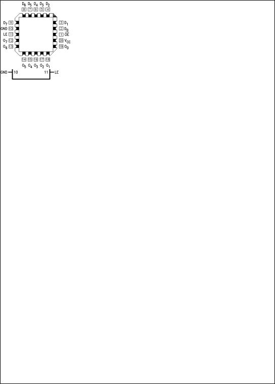
Connection Diagrams
Pin Assignment for LCC
Pin Assignment for DIP and Flatpak
DS100332-4
DS100332-3
www.national.com |
2 |

Functional Description
The 'ACT573 contains eight D-type latches with TRI-STATE output buffers. When the Latch Enable (LE) input is HIGH, data on the Dn inputs enters the latches. In this condition the latches are transparent, i.e., a latch output will change state each time its D input changes. When LE is LOW the latches store the information that was present on the D inputs a setup time preceding the HIGH-to-LOW transition of LE. The TRI-STATE buffers are controlled by the Output Enable (OE) input. When OE is LOW, the buffers are enabled. When OE is HIGH the buffers are in the high impedance mode but this does not interfere with entering new data into the latches.
Logic Diagram
Truth Table
|
|
|
Inputs |
|
Outputs |
|
|
|
|
|
|
|
OE |
|
LE |
D |
On |
|
L |
H |
H |
H |
|
|
L |
H |
L |
L |
|
|
L |
L |
X |
O0 |
|
|
H |
X |
X |
Z |
|
|
|
|
|
|
|
H = HIGH Voltage
L = LOW Voltage
Z = High Impedance X = Immaterial
O0 = Previous O0 before HIGH-to-LOW transition of Latch Enable
DS100332-5
Please note that this diagram is provided only for the understanding of logic operations and should not be used to estimate propagation delays.
3 |
www.national.com |
 Loading...