


Technical Manual
Inverter Systems and
Motors
for the Contouring Controls
TNC 410 M
TNC 426 M
TNC 430 M
MANUALplusM
February 2001
208 962-21 · 3 · 2/2001 · S · Printed in Germany · Subject to change without notice (208 962-E2)

Foreword
This Technical Manual has been written for all machine tool manufacturers. It contains all of the information necessary for the mounting and electrical connection of HEIDENHAIN inverter systems and HEIDENHAIN motors. With each update, you will receive a set of supplementary pages free-of- charge. Always sort these pages into your Technical Manual immediately. In this way, your manual will always be up-to-date.
You can use extracts from this manual to supplement your machine documentation. If you increase the size of the manual format (17 cm x 24 cm) by the factor 1.225, you will have DIN A4 format.
No documentation is perfect. Documentation is alive. It thrives on your comments and suggestions for improvement. Please help us by sending us your ideas.
DR. JOHANNES HEIDENHAIN GmbH
E/P Department
Dr.-Johannes-Heidenhain-Str. 5
83301 Traunreut
February 2001
208 962-21 · 3 · 2/2001 · S · Printed in Germany · Subject to change without notice (208 962-E2)

Contents Technical Manual Inverter Systems and Motors
Update Information
Introduction
Selection of Motors and Inverters
Mounting and Operating Conditions
UE 2xx and UE 2xxB Compact Inverters
Modular Inverters
Motors for Axis and Spindle Drives
1
2
3
4
5
6
7

2 Introduction
2.1 |
General Information ........................................................................ |
2 – 2 |
2.2 |
Designations of the Inverters and Motors..................................... |
2 – 2 |
2.3 |
Compact inverter ............................................................................. |
2 – 3 |
|
2.3.1 Components of the Compact Inverter ....................................... |
2 – 3 |
|
2.3.2 UE 2xx compact inverter ........................................................... |
2 – 4 |
|
2.3.3 UE 2xxB Compact Inverter ........................................................ |
2 – 5 |
|
2.3.4 PW 210 (PW 110, PW 120) Braking Resistor ............................ |
2 – 7 |
|
2.3.5 UV 102 power supply unit ......................................................... |
2 – 9 |
|
2.3.6 Toroidal Cores ......................................................................... |
2 – 10 |
|
2.3.7 Ribbon Cables and Covers (Only for UE 2xxB) ........................ |
2 – 10 |
2.4 |
Modular Inverters .......................................................................... |
2 – 13 |
|
2.4.1 Components of the modular inverter ...................................... |
2 – 13 |
|
2.4.2 UV 1x0 power supply unit ....................................................... |
2 – 14 |
|
2.4.3 KDR 1x0 commutating reactor and line filter .......................... |
2 – 16 |
|
2.4.4 UP 110 braking resistor module .............................................. |
2 – 18 |
|
2.4.5 PW 210 (PW 110, PW 120) braking resistor ........................... |
2 – 19 |
|
2.4.6 UM 1xx power modules .......................................................... |
2 – 20 |
|
2.4.7 Ribbon cables and covers ........................................................ |
2 – 22 |
February 2001 |
2 – 1 |

2 Introduction
2.1 General Information
This Technical Manual describes all of the inverter components and motors that are necessary for a complete drive system. The drive systems can be used in connection with the HEIDENHAIN contouring controls TNC 410 M, TNC 426 M, TNC 430 M and the lathe control MANUALplusM.
You will find the specifications for the controls in the corresponding Technical Manuals for the TNC 410, TNC 426/TNC 430 and MANUALplusM.
2.2 Designations of the Inverters and Motors
Designation |
Device |
UE 2xx |
Compact inverter for up to 4 axes and spindle |
|
(internal PWM interfaces) |
|
|
UE 2xxB |
Compact inverter for up to 4 axes and spindle |
|
(external PWM interfaces), an additional UM |
|
111 power module can be connected |
|
|
UV 102 |
Power supply unit for operating the LE 426M |
|
with the UE 2xx compact inverters (old) |
|
|
PW 210 |
Braking resistor without fan |
|
|
PW 110, PW 120 |
Braking resistor with fan |
|
|
UV 130 |
Non-regenerative power module of the |
|
modular inverter system |
|
|
UV 120, UV 140 |
Energy-recovery power modules of the |
|
modular inverter system |
|
|
KDR 120, KDR 140 |
Commutating reactors for the UV 120 and |
|
UV 140 energy-recovery power supply |
|
modules |
|
|
Line filter |
Line filter for the UV 120 and UV 140 energy- |
|
recovery power modules |
|
|
UP 110 |
UP 110 braking resistor module for the modular |
|
inverter system with regenerative power |
|
supply. |
|
|
UM 1xx |
Power module for the modular inverter system |
|
for up to 2 axes or spindle |
|
|
QSY |
Synchronous motor |
|
|
QAN |
Asynchronous motor |
|
|
2 – 2 |
HEIDENHAIN Technical Manual for Inverter Systems and Motors |

2.3 Compact inverter
For up to 4 axes and spindle, or up to 5 axes.
2.3.1 Components of the Compact Inverter
For operation with the HEIDENHAIN UE 2xx compact inverters, you need the following components:
nUE 2xx compact inverter
nIf required, PW 210 (or PW 110, PW 120) braking resistor
nToroidal cores
nUV 102 power supply unit (only LE 426 M)
For operation with the HEIDENHAIN UE 2xxB compact inverters, you need the following components:
nUE 2xxB compact inverter
nIf required, PW 210 (or PW 110, PW 120) braking resistor
nToroidal cores
nOne UM 111 power module (optional)
nRibbon cables for PWM signals and supply voltage (and optional unit bus)
nCovers for the ribbon cables
February 2001 |
Compact inverter |
2 – 3 |
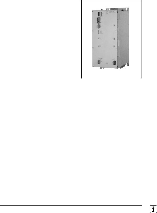
2.3.2 UE 2xx compact inverter
With UE 2xx compact inverters, the power electronics for all of the axes and the spindle, as well as the power supply for the LE 41x M are all contained in a single unit.
The PWM signals are transferred via internal 20-pin ribbon cables.
If you are using a LE 426 M, you will require in addition the UV 102 power supply unit.
|
|
|
UE 212 |
|
|
|
|
|
|
|
|
|
|
Specifications |
UE 210 |
UE 212 |
UE 230 |
UE 240 |
UE 242 |
|
Power Supply |
400 Vac ± 10 % |
|
|
|
||
|
50 Hz to 60 Hz |
|
|
|
||
|
|
|
|
|
|
|
Power consumption |
|
|
|
|
|
|
Rated power |
13 kW |
|
|
20 kW |
|
|
Peak power |
18 kW |
|
|
27.5 kW |
|
|
|
|
|
|
|
|
|
Power loss |
Approx. 435 |
Approx. 555 |
Approx. 510 |
Approx. 580 |
Approx. 760 |
|
|
W |
W |
W |
W |
W |
|
|
|
|
|
|
|
|
DC-link voltage |
565 Vdc (at 400 V power supply) |
|
|
|||
|
|
|
|
|
|
|
Continuous load |
|
|
|
|
|
|
3 axes |
7.5 A |
7.5 A |
2 x 7.5 A |
7.5 A |
7.5 A |
|
1 axis |
– |
14 A |
– |
– |
23 A |
|
spindle |
19 A |
19 A |
31 A |
31 A |
31 A |
|
|
|
|
|
|
|
|
Short-time loada |
|
|
|
|
|
|
3 axes |
15 A |
15 A |
2 x 15 A |
15 A |
15 A |
|
1 axis |
– |
28.5 A |
– |
– |
46 A |
|
spindle |
28.5 A |
28.5 A |
46 A |
46 A |
46 A |
|
|
|
|
|
|
|
|
Continuous power of the |
1 kW |
|
|
– |
– |
– |
integral braking resistor |
|
|
|
|
|
|
|
|
|
|
|
|
|
Peak power of the integral |
23 kW |
|
|
– |
– |
– |
braking resistorb |
|
|
|
|
|
|
Degree of protection |
IP 20 |
|
|
|
|
|
|
|
|
|
|
|
|
Weight |
20 kg |
|
|
23 kg |
|
|
|
|
|
|
|
|
|
ID number |
313 500-xx |
313 501-xx |
329 037-xx |
313 502-xx |
313 503-xx |
|
|
|
|
|
|
|
|
a.Axes: 40% cyclic duration factor for duration of 5 s
Spindle: 40 % cyclic duration factor for duration of 10 minutes (S6-40 %)
b.0.4 % cyclic duration factor for duration of 120 s
2 – 4 |
HEIDENHAIN Technical Manual for Inverter Systems and Motors |
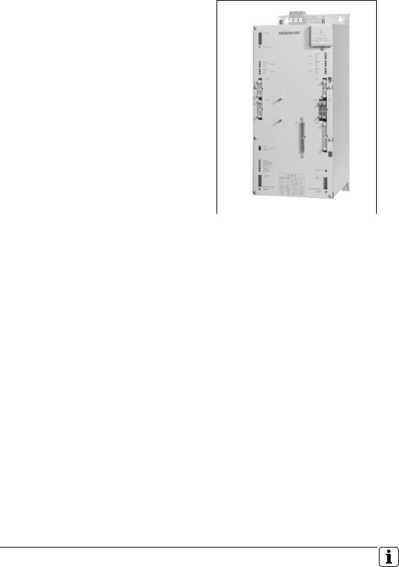
2.3.3 UE 2xxB Compact Inverter
With UE 2xxB compact inverters, the power electronics for all of the axes and the spindle, as well as the power supply for the LE are all contained in a single unit. An additional UM 111 power module of the modular inverter system can be connected via conductor bar.
The PWM signals are transferred via external 20 pin ribbon cables.
|
|
|
UE 242B |
|
|
|
|
|
|
|
|
Specifications |
UE 210B |
UE 211B |
UE 212B |
UE 230B |
|
Power Supply |
400 Vac ± 10 % |
|
|
|
|
|
50 Hz to 60 Hz |
|
|
|
|
|
|
|
|
|
|
Power consumption |
|
|
|
|
|
Rated power |
15 kW |
|
|
|
22 kW |
Peak power |
23 kW |
|
|
|
30 kW |
|
|
|
|
|
|
Power loss |
Approx. 475 W |
Approx. 525 W |
Approx. 595 W |
Approx. 520 W |
|
|
|
|
|
|
|
DC-link voltage |
565 Vdc (at 400 V power supply) |
|
|
||
|
|
|
|
|
|
Continuous load |
|
|
|
|
|
3 axes |
7.5 A |
2 x 7.5 A |
7.5 A |
2 x 7.5 A |
|
1 axis |
– |
15 A |
15 A |
– |
|
spindle |
20 A |
20 A |
20 A |
31 A |
|
|
|
|
|
|
|
Short-time loada |
|
|
|
|
|
3 axes |
15 A |
2 x 15 A |
15 A |
2 x 15 A |
|
1 axis |
– |
30 A |
30 A |
– |
|
spindle |
30 A |
30 A |
30A |
46 A |
|
|
|
|
|
|
|
Continuous power of the |
1 kW |
|
|
|
– |
integral braking resistor |
|
|
|
|
|
|
|
|
|
|
|
Peak power of the integral |
23 kW |
|
|
|
– |
braking resistorb |
|
|
|
|
|
Degree of protection |
IP 20 |
|
|
|
|
|
|
|
|
|
|
Weight |
20 kg |
|
|
|
23 kg |
|
|
|
|
|
|
ID number |
337 042-xx |
337 043-xx |
337 044-xx |
337 038-xx |
|
|
|
|
|
|
|
a.Axes: 40% cyclic duration factor for duration of 5 s
Spindle: 40 % cyclic duration factor for duration of 10 minutes (S6-40 %)
b.0.4 % cyclic duration factor for duration of 120 s
February 2001 |
Compact inverter |
2 – 5 |

Specifications |
UE 240B |
UE 241B |
UE 242B |
Power Supply |
400 Vac ± 10 % |
|
|
|
50 Hz to 60 Hz |
|
|
|
|
|
|
Power consumption |
|
|
|
Rated power |
22 kW |
|
|
Peak power |
30 kW |
|
|
|
|
|
|
Power loss |
Approx. 590 W |
Approx. 700 W |
Approx. 770 W |
|
|
|
|
DC-link voltage |
565 Vdc (at 400 V power supply) |
|
|
|
|
|
|
Continuous load |
|
|
|
3 axes |
7.5 A |
2 x 7.5 A |
7.5 A |
1 axis |
– |
23 A |
23 A |
spindle |
31 A |
31 A |
31 A |
|
|
|
|
Short-time loada |
|
|
|
3 axes |
15 A |
2 x 15 A |
15 A |
1 axis |
– |
46 A |
46 A |
spindle |
46 A |
46 A |
46 A |
|
|
|
|
Continuous power of the |
– |
|
|
integral braking resistor |
|
|
|
|
|
|
|
Peak power of the integral |
– |
|
|
braking resistor |
|
|
|
|
|
|
|
Degree of protection |
IP 20 |
|
|
|
|
|
|
Weight |
23 kg |
|
|
|
|
|
|
ID number |
337 039-xx |
337 040-xx |
337 041-xx |
|
|
|
|
a.Axes: 40% cyclic duration factor for duration of 5 s
Spindle: 40 % cyclic duration factor for duration of 10 minutes (S6-40 %)
Changes to the UE 2xxB
337 xxx-x2 |
First issue UE 2xxB |
|
|
337 xxx-x3 |
Only UE 230B and UE 24xB: |
|
new connections and sliding switch |
|
|
2 – 6 |
HEIDENHAIN Technical Manual for Inverter Systems and Motors |

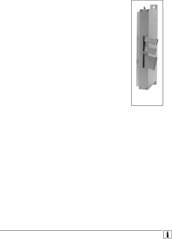
2.3.4 PW 210 (PW 110, PW 120) Braking Resistor
The PW braking resistors convert the energy fed back into the dc-link during braking into heat.
The PW 110 and PW 120 have a cooling fan, the PW 210 cools only through heat radiation.
Either one PW x10 or two PW 120 switched in series can be connected to the UE 2xx compact inverters. Either one PW 210, one PW 1x0 or two PW 210 in parallel can be connected to the UE 2xxB compact inverters and UV 130 power supply unit.
|
|
PW 1x0 |
PW 210 |
|
|
|
|
Specifications |
PW 210 |
|
|
Continuous power |
2 kW (4 kW)a |
|
|
Peak powerb |
27 kW (54 kW)a |
|
|
Resistance |
18 Ω |
|
|
|
|
|
|
Degree of protection |
IP 20 |
|
|
|
|
|
|
Weight |
5.5 kg |
|
|
|
|
|
|
ID number |
333 081-01 |
|
|
|
|
|
|
a.When two PW 210 are connected in parallel
b.2 % cyclic duration factor for duration of 120 s
February 2001 |
Compact inverter |
2 – 7 |
Specifications |
PW 110 |
PW 120 |
Continuous power |
2 kW |
4 kW |
|
|
|
Peak powera |
27 kW |
49 kW |
Power consumption of fan |
2,5 W |
2.4 W |
|
|
|
Resistance |
18 Ω |
10 Ω |
|
|
|
Degree of protection |
IP 20 |
IP 20 |
|
|
|
Weight |
6 kg |
11 kg |
|
|
|
ID number |
313 511-01 |
333 000-01 |
|
|
|
a.PW 110: 1.5 % cyclic duration factor for duration of 120 s PW 120: 2 % cyclic duration factor for duration of 120 s
Danger
The surface of the braking resistor can attain temperatures of up to > 150 °C!
2 – 8 |
HEIDENHAIN Technical Manual for Inverter Systems and Motors |
2.3.5 UV 102 power supply unit
The UV 102 power supply unit is necessary if you are using a UE 2xx (not UE 2xxB) compact inverter with an LE 426 M. It supplies the power to the LE 426 M and leads the external PWM connections of the logic unit to the UE 2xx compact inverter.
UV 102
Specifications |
UV 102 |
Power Supply |
400 Vac ± 10 % |
|
50 Hz to 60 Hz |
|
|
Power consumption |
Approx. 100 W |
|
|
Degree of protection |
IP 20 |
|
|
Weight |
3 kg |
|
|
ID number |
317 559-02 |
|
|
February 2001 |
Compact inverter |
2 – 9 |

2.3.6 Toroidal Cores
Line interference can be suppressed by mounting toroidal cores in the motor leads, the power supply leads and the lead to the braking resistor (only
UE 21x).
Terminal on the compact inverter |
Toroidal core |
Power supply (X31) |
87 mm (309 694-02) |
|
|
Braking resistor (X89)a |
42 mm (309 694-01) |
Axis 1 to 3 (X81 to X83) |
42 mm (309 694-01) |
|
|
Axis 4 (X84) |
59 mm (309 694-03) |
|
|
Spindle (X80) |
59 mm (309 694-03) |
|
|
a.Only with UE 21x; not with UE 230, UE 24x, UE 2xxB
2.3.7Ribbon Cables and Covers (Only for UE 2xxB)
50-line ribbon cable |
The 50-line ribbon cable connects the UE 2xxB with the LE and is responsible |
|||
(power supply to |
for voltage supply to the LE. It is available as an accessory with the UE 2xxB |
|||
LE) |
(length 300 mm, Id. Nr. 325 816-01). |
|
||
20-line ribbon cable |
The 20-line ribbon cable connects the PWM outputs of the LE with the PWM |
|||
(PWM signals) |
connections on the UE 2xxB. One 20-line ribbon cable is required for each axis/ |
|||
|
spindle. The 20-line ribbon cables for the connections on the UE 2xxB are |
|||
|
supplied as accessories with the UE 2xxB (length 200 mm, Id. Nr. 250 479-08; |
|||
|
length 400 mm, Id. Nr. 250 479-10). If you are using an additional UM 111 |
|||
|
power module, you will need an additional 20-line ribbon cable: |
|||
|
|
|
|
|
|
PWM connection on the |
Length of the 20-line |
|
ID number |
|
UM 111 power module |
ribbon cable |
|
|
|
X111, X112 |
100 mm |
|
250 479-07 |
|
|
|
|
|
40-line ribbon cable |
The 40-line ribbon cable serves as the unit bus. It is required if an additional |
|||
(unit bus) |
UM 111 power module is being operated with the UE 2xxB. |
|
||
|
|
|
|
|
|
Unit bus connection |
Length of the 40-line |
|
ID number |
|
|
ribbon cable |
|
|
|
X79 |
50 mm |
|
325 817-09 |
|
|
|
|
|
2 – 10 |
HEIDENHAIN Technical Manual for Inverter Systems and Motors |

Ribbon cable covers The ribbon cables must be covered to protect against interference.
The cover for the LE is supplied with the LE.
The cover for the UE 2xxB is supplied with the UE 2xxB.
If you are using an additional power module, the cover for this module must be ordered separately:
Additional power module |
Length of |
ID number |
|
the cover |
|
UM 111 |
50 mm |
329 031-05 |
|
|
|
February 2001 |
Compact inverter |
2 – 11 |

2 – 12 |
HEIDENHAIN Technical Manual for Inverter Systems and Motors |

2.4 Modular Inverters
2.4.1 Components of the modular inverter
For operation with the modular HEIDENHAIN non-regenerative inverters, the following components are required:
nUV 130 power supply unit
nUM 1xx power modules, depending on version
nPW 210 (or PW 110, PW 120) braking resistor
nRibbon cables for PWM signals, unit bus and power supply
nCovers for the ribbon cables
For operation with the modular HEIDENHAIN regenerative inverters, the following components are required:
nUV 120 or UV 140 power supply unit
nKDR 120 or KDR 140 commutating reactor
nLine filter
nIf required, UP 110 braking resistor module
nUM 1xx power modules, depending on version
nRibbon cables for PWM signals, unit bus and power supply
nCovers for the ribbon cables
February 2001 |
Modular Inverters |
2 – 13 |
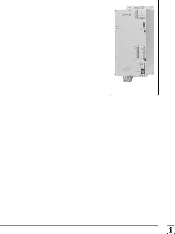
2.4.2 UV 1x0 power supply unit
The UV 1x0 power supply units supply the dc-link voltage as well as the power for the electronics of the LE and power modules.
During braking, the motors feed energy into the dc-link. This energy is converted into heat by the UV 130 through the PW 210 (or PW 1x0) braking resistor, or returned to the power line through the UV 120 or UV 140. The UV 120 and UV 140 can be driven only with commutating reactor and line filter.
|
|
|
UV 140 |
|
|
|
|
|
|
Specifications |
UV 120 |
UV 130 |
UV 140 |
|
Power Supply |
400 Vac ± 10 % |
|
||
|
50 Hz to 60 Hz |
|
|
|
|
|
|
|
|
DC-link power |
|
|
|
|
Continuous power |
22 kW |
30 kW |
45 kW |
|
Peak power (S6-40 %) |
30 kW |
40 kW |
65 kW |
|
|
|
|
|
|
Power loss |
Approx. 300 |
Approx. 140 |
Approx. 570 |
|
|
W |
W |
W |
|
|
|
|
|
|
DC-link voltage |
650 Vdc |
565 Vdc |
650 Vdc |
|
|
|
|
(with 400 V |
|
|
|
|
power |
|
|
|
|
voltage) |
|
|
|
|
|
|
Degree of protection |
IP 20 |
|
|
|
|
|
|
|
|
Weight |
12 kg |
9.8 kg |
20 kg |
|
|
|
|
|
|
ID number |
344 504-xx |
324 998-xx |
335 009-xx |
|
|
|
|
|
|
2 – 14 |
HEIDENHAIN Technical Manual for Inverter Systems and Motors |

Changes to UV 120
345 504-01 |
Initial version |
|
|
|
|
Changes to UV 130 |
|
324 998-01 |
Initial version |
|
|
324 998-02 |
Modification |
|
|
324 998-03 |
Modification |
|
|
|
|
Changes to UV 140 |
|
335 009-01 |
Initial version |
|
|
335 009-02 |
Modification |
|
|
February 2001 |
Modular Inverters |
2 – 15 |
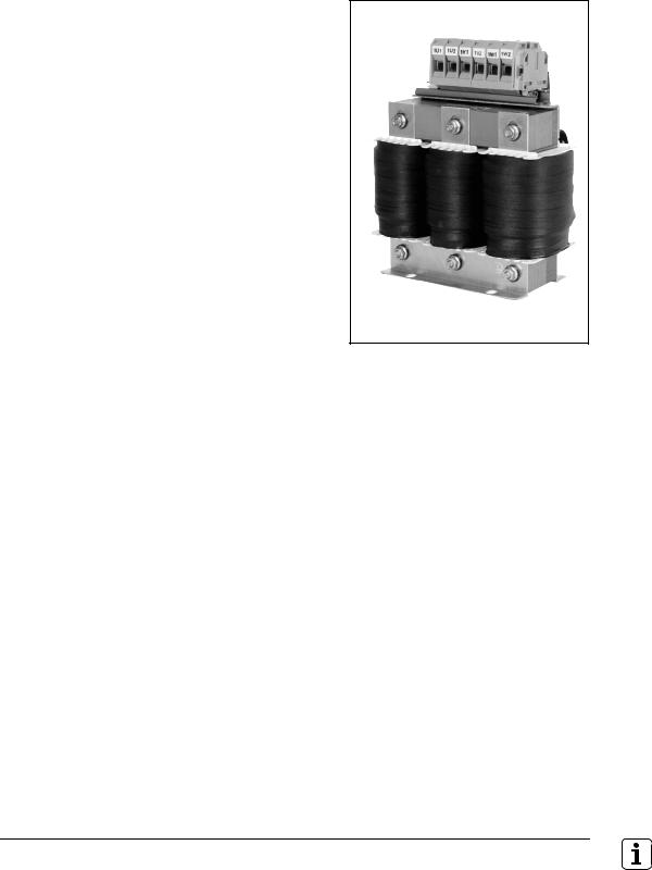
2.4.3 KDR 1x0 commutating reactor and line filter
The UV 120 and UV 140 power recovery modules must be connected to the main power line via the KDR 140 commutating reactor and the line filter. This is important to keep the main line free of disruptive higher harmonics.
KDR 140
|
KDR 120 |
KDR 140 |
Rated voltage |
3 x 400 V |
3 x 400 V |
|
|
|
Rated frequency |
50 Hz/60 Hz |
50 Hz/60 Hz |
|
|
|
Rated current |
3 x 35 A |
3 x 70 A |
|
|
|
Power loss |
Approx. 200 W |
Approx. 340 W |
|
|
|
Degree of protection |
IP 00 |
IP 00 |
|
|
|
Weight |
11 kg |
22 kg |
|
|
|
ID number |
344 505-01 |
333 068-01 |
|
|
|
2 – 16 |
HEIDENHAIN Technical Manual for Inverter Systems and Motors |
EPCOS 80 A line filter
|
EPCOS 35 A line filter |
EPCOS 80 A line filter |
suitable for |
UV 120 |
UV 140 |
|
|
|
Rated voltage |
3 x 400 V |
3 x 400 V |
|
|
|
Rated frequency |
50 Hz/60 Hz |
50 Hz/60 Hz |
|
|
|
Rated current |
3 x 35 A |
3 x 80 A |
|
|
|
Degree of protection |
IP 20 |
IP 20 |
|
|
|
Weight |
5 kg |
10 kg |
|
|
|
ID number |
340 691-01 |
340 651-01 |
|
|
|
February 2001 |
Modular Inverters |
2 – 17 |
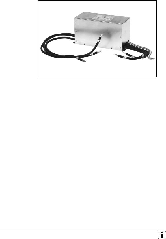
2.4.4 UP 110 braking resistor module
In the energy-recovery inverter, the braking energy of the motors is normally returned to the line power. If in an exceptional case the line power is interrupted, the braking energy cannot be returned. This can lead to an excessive dc-link voltage that might switch off the inverter and let the motors coast without control. To prevent damage to the machine and workpiece resulting from uncontrolled machine movement, the axis motors must be equipped with brakes, or the energy must be dissipated with the UP 110 braking resistor module.
UP 110
Specifications |
UP 110 |
Power |
60 kW (for 2 s) |
|
|
Resistance |
9 Ω |
|
|
Degree of protection |
IP 20 |
|
|
Weight |
7 kg |
|
|
ID number |
341 516-01 |
|
|
2 – 18 |
HEIDENHAIN Technical Manual for Inverter Systems and Motors |
|
|
|
|
|
|

2.4.5 PW 210 (PW 110, PW 120) braking resistor
You will find information on the UV 130 braking resistor under ”2.3.4 PW 210 (PW 110, PW 120) Braking Resistor” on page 2 – 7.
February 2001 |
Modular Inverters |
2 – 19 |
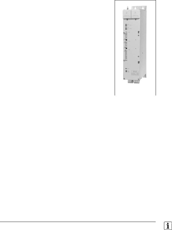
2.4.6 UM 1xx power modules
The power modules differ in the number of axes and the permissible maximum currents. They can be combined at random. The PWM signals are transferred from the LE via external 20-line ribbon cables.
|
|
|
|
|
UM 121B |
|
|
|
|
|
|
|
|
Specifications |
UM 111 |
UM 111B |
UM 112 |
UM 113 |
UM 114 |
|
Continuous load |
|
|
|
|
|
|
Axis |
1 x 7.5 A |
1 x 15 A |
1 x 23 A |
1 x 32 A |
1 x 48 A |
|
spindle |
– |
20 A |
31 A |
50 A |
75 A |
|
|
|
|
|
|
|
|
Short-time loada |
|
|
|
|
|
|
|
15 A |
30 A |
46 A |
64 A |
96 A |
|
|
|
|
|
|
|
|
Power loss |
60 W |
120 W |
250 W |
420 W |
650 W |
|
|
|
|
|
|
|
|
Degree of protection |
IP 20 |
|
|
|
|
|
|
|
|
|
|
|
|
Weight |
5.5 kg |
9 kg |
9 kg |
9 kg |
12 kg |
|
|
|
|
|
|
|
|
ID number |
325 000-xx |
336 948-xx |
325 001-xx |
325 002-xx |
325 005-xx |
|
|
|
|
|
|
|
|
a.Axes: 40% cyclic duration factor for duration of 5 s
Spindle: 40% cyclic duration factor for duration of 10 minutes (S6-40%)
2 – 20 |
HEIDENHAIN Technical Manual for Inverter Systems and Motors |

Specifications |
UM 121 |
UM 121B |
UM 122 |
Continuous load |
|
|
|
Axis |
2 x 7.5 A |
2 x 15 A |
2 x 23 A |
spindle |
– |
20 A |
31 A |
|
|
|
|
Short-time loada |
|
|
|
|
15 A |
30 A |
46 A |
|
|
|
|
Power loss |
120 W |
240 W |
450 W |
|
|
|
|
Degree of protection |
IP20 |
|
|
|
|
|
|
Weight |
5.5 kg |
9 kg |
9 kg |
|
|
|
|
ID number |
325 003-xx |
336 949-xx |
325 004-xx |
|
|
|
|
a.Axes: 40% cyclic duration factor for duration of 5 s
Spindle: 40 % cyclic duration factor for duration of 10 minutes (S6-40 %)
Changes to UM 1x1
xxx xxx-01 |
Initial version |
|
|
xxx xxx-02 |
New connections |
|
|
|
|
Changes to UM 1x1B |
|
xxx xxx-02 |
Initial version |
|
|
xxx xxx-03 |
New connections |
|
|
|
|
Changes to UM 1x2 |
|
xxx xxx-01 |
Initial version |
|
|
xxx xxx-02 |
New connections |
|
|
|
|
Changes to UM 113 and UM 114 |
|
xxx xxx-01 |
Initial version |
|
|
xxx xxx-02 |
New connections |
|
|
February 2001 |
Modular Inverters |
2 – 21 |

2.4.7 Ribbon cables and covers
50-line ribbon cable (power supply to LE)
The 50-line ribbon cable connects the UV 1x0 with the LE and serve as voltage supply to the LE. With lengths of 600 mm and longer, the ribbon cable is led doubled to the LE to increase the line cross section. This cable is only required once.
When using the UV 130:
325 816-xx |
|
Number of modules with 50 mm width (including UP 110) |
||||||||||
(order length [mm]) |
|
0 |
|
1 |
|
2 |
|
3 |
|
4 |
|
5 |
|
|
|
|
|
|
|||||||
|
|
|
|
|
|
|
||||||
|
1 |
– |
|
xx = 01 |
|
xx = 02 |
|
xx = 02 |
|
xx = 03 |
|
xx = 03 |
|
|
|
|
(300) |
|
(400) |
|
(400) |
|
(500) |
|
(500) |
|
2 |
xx = 02 |
|
xx = 02 |
|
xx = 03 |
|
xx = 03 |
|
xx = 04 |
|
xx = 04 |
|
|
(400) |
|
(400) |
|
(500) |
|
(500) |
|
(600) |
|
(600) |
|
3 |
xx = 03 |
|
xx = 03 |
|
xx = 04 |
|
xx = 04 |
|
xx = 05 |
|
– |
|
|
(500) |
|
(500) |
|
(600) |
|
(600) |
|
(700) |
|
|
Number of modules |
4 |
xx = 04 |
|
xx = 04 |
|
xx = 05 |
|
xx = 05 |
|
– |
|
– |
with 100 mm width |
|
(600) |
|
(600) |
|
(700) |
|
(700) |
|
|
|
|
|
5 |
xx = 05 |
|
xx = 05 |
|
xx = 06 |
|
– |
|
– |
|
– |
|
|
(700) |
|
(700) |
|
(800) |
|
|
|
|
|
|
|
6 |
xx = 06 |
|
xx = 06 |
|
– |
|
– |
|
– |
|
– |
|
|
(800) |
|
(800) |
|
|
|
|
|
|
|
|
|
7 |
xx = 07 |
|
– |
|
– |
|
– |
|
– |
|
– |
|
|
(900) |
|
|
|
|
|
|
|
|
|
|
|
|
|
|
|
|
|
|
|
|
|
|
|
When using the UV 120 or UV 140:
325 816-xx |
|
Number of modules with 50 mm width (including UP 110) |
||||||||||
(order length [mm]) |
|
0 |
|
1 |
|
2 |
|
3 |
|
4 |
|
5 |
|
|
|
|
|
|
|||||||
|
|
|
|
|
|
|
||||||
|
1 |
– |
|
xx = 01 |
|
xx = 01 |
|
xx = 02 |
|
xx = 02 |
|
xx = 03 |
|
|
|
|
(300) |
|
(300) |
|
(400) |
|
(400) |
|
(500) |
|
2 |
xx = 01 |
|
xx = 02 |
|
xx = 02 |
|
xx = 03 |
|
xx = 03 |
|
xx = 04 |
|
|
(300) |
|
(400) |
|
(400) |
|
(500) |
|
(500) |
|
(600) |
|
3 |
xx = 02 |
|
xx = 03 |
|
xx = 03 |
|
xx = 04 |
|
xx = 04 |
|
– |
|
|
(400) |
|
(500) |
|
(500) |
|
(600) |
|
(600) |
|
|
Number of modules |
4 |
xx = 03 |
|
xx = 04 |
|
xx = 04 |
|
xx = 05 |
|
– |
|
– |
with 100 mm width |
|
(500) |
|
(600) |
|
(600) |
|
(700) |
|
|
|
|
|
5 |
xx = 04 |
|
xx = 05 |
|
xx = 05 |
|
– |
|
– |
|
– |
|
|
(600) |
|
(700) |
|
(700) |
|
|
|
|
|
|
|
6 |
xx = 05 |
|
xx = 06 |
|
– |
|
– |
|
– |
|
– |
|
|
(700) |
|
(800) |
|
|
|
|
|
|
|
|
|
7 |
xx = 06 |
|
– |
|
– |
|
– |
|
– |
|
– |
|
|
(800) |
|
|
|
|
|
|
|
|
|
|
|
|
|
|
|
|
|
|
|
|
|
|
|
2 – 22 |
HEIDENHAIN Technical Manual for Inverter Systems and Motors |
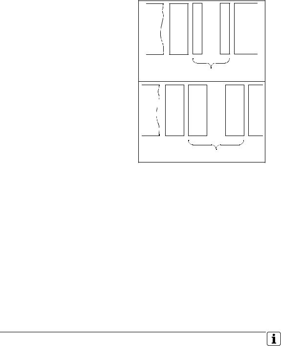
20-line ribbon cable (PWM signals)
The 20-line ribbon cable connects the PWM outputs of the LE with the corresponding UM 1xx power modules. One 20-line ribbon cable is required for each axis or spindle.
The LE 430 M/9 axes was used as the basis for creating the tables, since this control requires the greatest cable length. These cables also can be used for all other controls.
The following table is for the connection between the LE and a module with 100 mm width.
The table rows indicate the number of modules with 50 mm width (incl. UP 110) between the LE and a module with 100 mm width
The table rows indicate the number of modules with 100 mm width between the LE and a module with 100 mm width
.... |
LE |
? |
|
.... |
LE |
? |
|
250 479-xx |
|
Number of modules with 50 mm width (incl. UP 110) between the LE |
||||||||
(order length [mm]) |
|
|
and a module with 100 mm width |
|
|
|||||
|
|
0 |
|
2 |
|
3 |
|
4 |
|
5 |
|
|
1 |
|
|
|
|||||
|
0 |
xx = 08 |
xx = 09 |
xx = 09 |
|
xx = 10 |
|
xx = 10 |
|
xx = 11 |
|
|
(200) |
(300) |
(300) |
|
(400) |
|
(400) |
|
(500) |
|
1 |
xx = 09 |
xx = 10 |
xx = 10 |
|
xx = 11 |
|
xx = 11 |
|
xx = 12 |
|
|
(300) |
(400) |
(400) |
|
(500) |
|
(500) |
|
(600) |
|
2 |
xx = 10 |
xx = 11 |
xx = 11 |
|
xx = 12 |
|
xx = 12 |
|
– |
Number of modules with |
|
(400) |
(500) |
(500) |
|
(600) |
|
(600) |
|
|
100 mm width between |
3 |
xx = 11 |
xx = 12 |
xx = 12 |
|
xx = 13 |
|
– |
|
– |
the LE and a module with |
|
(500) |
(600) |
(600) |
|
(700) |
|
|
|
|
100 mm width |
4 |
xx = 12 |
xx = 13 |
xx = 13 |
|
– |
|
– |
|
– |
|
|
(600) |
(700) |
(700) |
|
|
|
|
|
|
|
5 |
xx = 13 |
xx = 14 |
– |
|
– |
|
– |
|
– |
|
|
(700) |
(800) |
|
|
|
|
|
|
|
|
6 |
xx = 14 |
– |
– |
|
– |
|
– |
|
– |
|
|
(800) |
|
|
|
|
|
|
|
|
|
|
|
|
|
|
|
|
|
|
|
February 2001 |
Modular Inverters |
2 – 23 |
The following table is for the connection between the LE and a module with 50 mm width.
.... |
LE |
|
|
|
|
|
? |
|
|
|
|
|
|
|
|
|
|
||
|
|
|
|
|
|
|||
250 479-xx |
Number of modules with 50 mm width (incl. UP 110) between the |
|||||||
(order length [mm]) |
|
LE and a module with 50 mm width |
|
|
||||
|
0 |
|
|
2 |
|
3 |
|
4 |
|
1 |
|
|
|
||||
|
xx = 08 |
xx = 08 |
xx = 09 |
|
xx = 09 |
|
xx = 10 |
|
|
(200) |
(200) |
(300) |
|
(300) |
|
(400) |
|
|
|
|
|
|
|
|
|
|
40-line ribbon cable The 40-line ribbon cable connects the UV 1x0 with all of the UM 1xx power
(unit bus) |
modules, making the unit bus. This cable is only required once. |
|
|||||||||||
|
|
|
|
|
|
|
|
|
|
|
|
|
|
325 817-xx |
|
|
Number of modules with 50 mm width (including UP 110) |
||||||||||
(order length [mm]) |
|
|
0 |
|
1 |
|
2 |
|
3 |
|
4 |
|
5 |
|
|
|
|
|
|
|
|||||||
|
|
|
|
|
|
|
|
||||||
|
1 |
xx = 01 |
|
xx = 01 |
|
xx = 01 |
|
xx = 01 |
|
xx = 02 |
|
xx = 02 |
|
|
|
|
(300) |
|
(300) |
|
(300) |
|
(300) |
|
(400) |
|
(400) |
|
|
2 |
xx = 01 |
|
xx = 01 |
|
xx = 02 |
|
xx = 02 |
|
xx = 03 |
|
xx = 03 |
|
|
|
(300) |
|
(300) |
|
(400) |
|
(400) |
|
(500) |
|
(500) |
|
|
3 |
xx = 01 |
|
xx = 02 |
|
xx = 03 |
|
xx = 03 |
|
xx = 04 |
|
– |
|
|
|
(300) |
|
(400) |
|
(500) |
|
(500) |
|
(600) |
|
|
Number of modules |
|
4 |
xx = 02 |
|
xx = 03 |
|
xx = 04 |
|
xx = 04 |
|
– |
|
– |
with 100 mm width |
|
|
(400) |
|
(500) |
|
(600) |
|
(600) |
|
|
|
|
|
5 |
xx = 03 |
|
xx = 04 |
|
xx = 05 |
|
– |
|
– |
|
– |
|
|
|
|
(500) |
|
(600) |
|
(700) |
|
|
|
|
|
|
|
|
6 |
xx = 04 |
|
xx = 05 |
|
– |
|
– |
|
– |
|
– |
|
|
|
(600) |
|
(700) |
|
|
|
|
|
|
|
|
|
|
7 |
xx = 05 |
|
– |
|
– |
|
– |
|
– |
|
– |
|
|
|
(700) |
|
|
|
|
|
|
|
|
|
|
|
|
|
|
|
|
|
|
|
|
|
|
|
|
2 – 24 |
HEIDENHAIN Technical Manual for Inverter Systems and Motors |

Ribbon cable covers The ribbon cables must be covered to protect against interference.
A cover is supplied as an accessory with the UV 1x0 (Id. Nr. 329 031-03), which protects the following modules:
nUV 1x0
nOne UM 1xx (100 mm width)
nOne UM 1xx (50 mm width)
The cover for the LE is supplied with the LE.
If further axis modules are used, the corresponding covers must be ordered separately:
Quantity y * 329 031-xx |
Number of modules with 50 mm width (including UP 110) |
|||||||||
(Length [mm]) |
0 |
|
2 |
|
3 |
|
4 |
|
5 |
|
1 |
|
|
|
|||||||
1 |
– |
– |
1 * 05 |
|
1 * 10 |
|
1 * 15 |
|
1 * 20 |
|
|
|
|
|
(50) |
|
(100) |
|
(150) |
|
(200) |
|
2 |
1 * 05 |
1 * 10 |
1 * 15 |
|
1 * 20 |
|
1 * 20 |
|
1 * 20 |
|
|
(50) |
(100) |
(150) |
|
(200) |
|
(200) |
|
(200) |
|
|
|
|
|
|
|
|
1 * 05 |
|
1 * 10 |
|
|
|
|
|
|
|
|
(50) |
|
(100) |
|
3 |
1 *15 |
1 * 20 |
1 * 20 |
|
1 * 20 |
|
1 * 20 |
|
– |
|
|
(150) |
(200) |
(200) |
|
(200) |
|
(200) |
|
|
Number of modules |
|
|
1 * 05 |
|
1 * 10 |
|
1 * 15 |
|
|
|
|
|
(50) |
|
(100) |
|
(150) |
|
|
||
with 100 mm width |
|
|
|
|
|
|
|
|||
|
4 |
1 * 20 |
1 * 20 |
1 * 20 |
|
2 * 20 |
|
– |
|
– |
|
|
(200) |
(200) |
(200) |
|
(200) |
|
|
|
|
|
|
1 * 05 |
1 * 10 |
1 * 15 |
|
|
|
|
|
|
|
|
(50) |
(100) |
(150) |
|
|
|
|
|
|
|
5 |
1 * 20 |
2 * 20 |
2 * 20 |
|
– |
|
– |
|
– |
|
|
(200) |
(200) |
(200) |
|
|
|
|
|
|
|
|
1 * 15 |
|
1 * 05 |
|
|
|
|
|
|
|
|
(150) |
|
(50) |
|
|
|
|
|
|
|
6 |
2 * 20 |
2 * 20 |
– |
|
– |
|
– |
|
– |
|
|
(200) |
(200) |
|
|
|
|
|
|
|
|
|
1 * 05 |
1 * 10 |
|
|
|
|
|
|
|
|
|
(50) |
(100) |
|
|
|
|
|
|
|
|
7 |
2 * 20 |
– |
– |
|
– |
|
– |
|
– |
|
|
(200) |
|
|
|
|
|
|
|
|
|
|
1 * 15 |
|
|
|
|
|
|
|
|
|
|
(150) |
|
|
|
|
|
|
|
|
|
|
|
|
|
|
|
|
|
|
|
February 2001 |
Modular Inverters |
2 – 25 |

2 – 26 |
HEIDENHAIN Technical Manual for Inverter Systems and Motors |

3 Selection of Motors and Inverters
3.1 |
Selection of the Axis Motor ............................................................ |
3 – 2 |
3.2 |
Selection of the Spindle Motor....................................................... |
3 – 6 |
3.3 |
Selection of the Inverter.................................................................. |
3 – 6 |
3.4 |
Selection of the braking resistor .................................................... |
3 – 7 |
February 2001 |
3 – 1 |
 Loading...