


Inverter Systems and Motors
Table of contents
 Loading...
June 2008
Service Manual
Inverter Systems
and Motors


1 Safety Precautions .................................................................................................................................................... 7
1.1 Target Group ...................................................................................................................................................... 7
1.2 Meaning of the Symbols Used in this Manual.................................................................................................... 7
1.3 Please Observe: ................................................................................................................................................. 8
1.4 With Inverter Systems, Especially Remember:.................................................................................................. 9
1.5 With Motors, Especially Remember: ............................................................................................................... 10
2 How to Use this Service Manual............................................................................................................................ 11
2.1 About this Manual ............................................................................................................................................ 11
2.2 Further Service Manuals .................................................................................................................................. 12
2.3 Other Documentation....................................................................................................................................... 12
2.4 Support............................................................................................................................................................. 12
2.5 Service Training Seminars ................................................................................................................................ 12
2.6 Safety ............................................................................................................................................................... 12
3 Errors and Error Messages ..................................................................................................................................... 13
3.1 Introduction ...................................................................................................................................................... 13
3.2 Overview of Possible Errors............................................................................................................................. 14
3.3 Important Notes on the Use of HEIDENHAIN Expansion Boards in the
SIMODRIVE System ........................................................................................................................................ 17
3.4 Error Messages on the Monitor of the Control ................................................................................................ 23
4 Explanation of the LEDs.......................................................................................................................................... 25
4.1 Compact Inverters............................................................................................................................................ 25
4.2 Power supply units........................................................................................................................................... 28
4.3 Power Modules ................................................................................................................................................ 30
4.4 HEIDENHAIN Interface Cards for the SIMODRIVE System............................................................................. 31
4.4.1 Boards with Ribbon Cable Connection for the PWM Interface............................................................... 31
4.4.2 Boards with D-sub Connection for the PWM Interface........................................................................... 31
5 Procedures and Tips for Error Diagnosis............................................................................................................... 33
5.1 Introduction ...................................................................................................................................................... 33
5.2 Sequence for Finding Errors in Digital Drives ................................................................................................... 33
5.3 Sequence for Finding Errors in the Control Loop ............................................................................................. 35
5.4 Error Localization by Process of Interchange ................................................................................................... 37
5.5 Notes and Tips ................................................................................................................................................. 38
6 Troubleshooting on Motors.................................................................................................................................... 45
6.1 Safety ............................................................................................................................................................... 45
6.2 Possible Causes of Error .................................................................................................................................. 45
6.3 Visual Inspection .............................................................................................................................................. 46
6.4 Trouble Shooting on Ground Fault.................................................................................................................... 47
6.5 Inspection for Winding Short Circuit or Interruption......................................................................................... 50
6.6 Inspection of the Motor Encoder ..................................................................................................................... 53
6.7 Inspection of the Fan.......................................................................................................
................................. 61
6.8 Inspection of the Temperature Sensor............................................................................................................. 62
6.9 Inspection of the Motor Brakes........................................................................................................................ 64
6.10 Inspection for Unbalance.................................................................................................................................. 66
7 Error Diagnosis on the Inverter System................................................................................................................ 67
7.1 Safety ............................................................................................................................................................... 67
7.2 Possible Causes of Error .................................................................................................................................. 67
7.3 Visual Inspection .............................................................................................................................................. 68
7.4 Checking the Criteria for Water-Cooled Inverters............................................................................................. 69
7.5 Error Diagnosis on the UV, UVR Power Supply Unit ........................................................................................ 71
7.5.1 Inspection for Ground Fault..................................................................................................................... 71
7.5.2 Inspection for Short Circuit or Interruption.............................................................................................. 74
7.5.3 Checking the fuses.................................................................................................................................. 78
7.5.4 Checking the Braking Resistor Switch .................................................................................................... 79
7.5.5 Checking the LEDs.................................................................................................................................. 81
7.5.6 Checking the Voltages............................................................................................................................. 82
7.6 Error Diagnosis on the UM Power Module ...................................................................................................... 88
7.6.1 Inspection for Ground Fault..................................................................................................................... 88
7.6.2 Inspection for Short Circuit or Interruption.............................................................................................. 91
7.6.3 Checking the LEDs.................................................................................................................................. 96

HEIDENHAIN Service-Handbuch Umrichter-Systeme und Motoren
7.6.4 Checking the Voltages............................................................................................................................. 98
7.6.5 Exchanging Power Modules or Output Stages of the Same Type........................................................ 100
7.6.6 Exchanging the PWM Interfaces........................................................................................................... 103
7.7 Error Diagnosis on the UE, UR Compact Inverter .......................................................................................... 104
7.7.1 Inspection for Ground Fault................................................................................................................... 104
7.7.2 Inspection for Short Circuit or Interruption............................................................................................ 107
7.7.3 Checking the Fuses............................................................................................................................... 113
7.7.4 Checking the Internal Braking Resistor ................................................................................................. 114
7.7.5 Checking the Braking Resistor Switch .................................................................................................. 116
7.7.6 Checking the LEDs................................................................................................................................ 119
7.7.7 Checking the Voltages........................................................................................................................... 122
7.7.8 Exchanging Output Stages of the Same Type ...................................................................................... 128
7.7.9 Exchanging the PWM Interfaces........................................................................................................... 131
7.8 Error Diagnosis on Non-HEIDENHAIN Inverter Systems .............................................................................. 132
7.8.1 Inspection for Ground Fault................................................................................................................... 132
7.8.2 Inspection for Short Circuit or Interruption............................................................................................ 132
7.8.3 Checking the Displays on the Infeed/Regenerative Module of the Non-HEIDENHAIN Manufacturer.. 133
7.8.4 Checking the LEDs on the HEIDENHAIN Expansion Boards ................................................................ 133
7.8.5 Checking the Voltages........................................................................................................................... 134
7.8.6 Exchanging the HEIDENHAIN Expansion Boards for the SIMODRIVE 611 System............................. 135
7.8.7 Exchanging Output Stages of the Same Type ...................................................................................... 136
7.8.8 Exchanging the PWM interfaces........................................................................................................... 138
8 Error Diagnosis on Accessories............................................................................................................................ 139
8.1 Safety ............................................................................................................................................................. 139
8.2 Possible Causes of Error ................................................................................................................................ 139
8.3 Visual Inspection ............................................................................................................................................ 139
8.4 Error Diagnosis on the PW Braking Resistor .................................................................................................. 140
8.4.1 Inspection for Ground Fault................................................................................................................... 140
8.4.2 Checking the Resistance Value............................................................................................................. 143
8.4.3 Checking the Fan................................................................................................................................... 144
8.4.4 Checking the Temperature Switch........................................................................................................ 144
8.5 Error Diagnosis on the UP 1x0 Braking Resistor Module ............................................................................... 145
8.5.1 Inspection for Ground Fault................................................................................................................... 145
8.5.2 Inspection for Short Circuit.................................................................................................................... 148
8.5.3 Checking the Resistance Value............................................................................................................. 150
8.5.4 Checking the Braking Resistor Switch ......................................................................................
............ 151
8.5.5 Checking the Temperature Switch........................................................................................................ 154
8.6 Error Diagnosis on the SM Voltage Protection Module.................................................................................. 155
8.6.1 Inspection for Short Circuit.................................................................................................................... 155
8.6.2 Checking the Temperature Switch........................................................................................................ 158
9 Error Diagnosis on UV Power Supply Units ....................................................................................................... 159
9.1 Safety ............................................................................................................................................................. 159
9.2 Possible Causes of Error ................................................................................................................................ 159
9.3 Error Diagnosis on UV 101 B.......................................................................................................................... 160
9.4 Error Diagnosis on the UV 102 ...................................................................................................................... 163
9.5 Error Diagnosis on UV 105, UV 105 B ............................................................................................................ 165
9.6 Error Diagnosis on UV 106 B.......................................................................................................................... 171
9.7 Error Diagnosis on the UV 111A, UV 111B .................................................................................................... 173
10 Exchanging HEIDENHAIN Components .............................................................................................................. 175
10.1 Important Notes ............................................................................................................................................. 175
10.2 Exchanging the Complete Inverter................................................................................................................. 178
10.3 Exchanging the Complete Motor ................................................................................................................... 180
10.4 Exchanging the Motor Encoder of the QAN Asynchronous Motor ................................................................ 181
10.5 Exchanging the Signal Socket of the Motor ................................................................................................... 184
10.6 Exchanging the Fan of a Spindle Motor ......................................................................................................... 186
10.7 Exchanging the Fan Guard of a Spindle Motor............................................................................................... 191
10.8 Changing Connections to the Reserve Temperature Sensor ......................................................................... 194
10.9 Exchanging Inverter Accessories ................................................................................................................... 195
10.10 Exchanging Cables and Connectors ............................................................................................................... 196
10.11 Exchanging Power Supply Units .............................................................................................
....................... 197
10.11.1 Exchanging the UV 101 B Power Supply Unit ....................................................................................... 197
10.11.2 Exchanging the UV 102 Power Supply Unit .......................................................................................... 197

10.11.3 Exchanging the UV 105 Power Supply Unit .......................................................................................... 198
10.11.4 Exchanging the UV 105 B Power Supply Unit ....................................................................................... 199
10.11.5 Exchanging the UV 106 B Power Supply Unit ....................................................................................... 200
10.11.6 Exchanging the UV 111 A, UV 111 B Power Supply Units .................................................................... 201
11 Overview of Components..................................................................................................................................... 203
11.1 Compact Inverters.......................................................................................................................................... 203
11.1.1 Assembly............................................................................................................................................... 203
11.1.2 UE 1xx Compact Inverter ...................................................................................................................... 204
11.1.3 UE 2xx compact inverter ....................................................................................................................... 204
11.1.4 UE 2xxB Compact Inverter.................................................................................................................... 205
11.1.5 UR 2xx(D) Compact Inverter ................................................................................................................. 205
11.1.6 Toroidal Cores ....................................................................................................................................... 206
11.1.7 Ribbon Cables and Covers (Only for UE 2xxB, UR 2xx) ........................................................................ 206
11.2 Modular Inverters ........................................................................................................................................... 207
11.2.1 Assembly............................................................................................................................................... 207
11.2.2 UV 130(D) Power Supply Unit ............................................................................................................... 208
11.2.3 UV(R) 1x0(D) Power Supply Unit ........................................................................................................... 208
11.2.4 UM 1xx(B)(D) Power Modules .............................................................................................................. 209
11.2.5 Ribbon Cables and Covers .................................................................................................................... 209
11.3 Accessories for Compact Inverters and Modular Inverters............................................................................ 210
11.3.1 PW 21x, PW 110(B), PW 120 Braking Resistors................................................................................... 210
11.3.2 UP 110, UP 120 Braking Resistor Module (Optional) ............................................................................ 211
11.3.3 Line Filters............................................................................................................................................. 212
11.3.4 Three-Phase Capacitor .......................................................................................................................... 214
11.3.5 KDR 1x0(B) Commutating Reactor........................................................................................................ 215
11.3.6 ZKF 1x0 DC-Link Filter........................................................................................................................... 216
11.3.7 SM 1xx Voltage Protection Module....................................................................................................... 218
11.3.8 Adapter Module...........................................................................................................
.......................... 219
11.3.9 Axis-Release Module............................................................................................................................. 220
11.3.10 Capacitor Module .................................................................................................................................. 221
11.4 HEIDENHAIN interface cards for the SIMODRIVE system............................................................................ 222
11.4.1 Assembly............................................................................................................................................... 222
11.4.2 Expansion Boards.................................................................................................................................. 222
11.5 Power Supply Unit.......................................................................................................................................... 223
11.5.1 UV 101 B Power Supply Unit ................................................................................................................ 223
11.5.2 UV 102 Power Supply Unit.................................................................................................................... 224
11.5.3 UV 105 Power Supply Unit.................................................................................................................... 225
11.5.4 UV 105 B Power Supply Unit ................................................................................................................ 225
11.5.5 UV 106 B Power Supply Unit ................................................................................................................ 226
11.5.6 UV 111 A, UV 111 B Power Supply Units ............................................................................................. 226
11.6 HEIDENHAIN Motors ..................................................................................................................................... 227
12 Connector Designation and Layout ..................................................................................................................... 229
12.1 Important Note ............................................................................................................................................... 229
12.2 Compact Inverters.......................................................................................................................................... 229
12.2.1 Designation and Position of Connections ............................................................................................. 229
12.2.2 Pin Layout on the Compact Inverter...................................................................................................... 247
12.3 Power supply units......................................................................................................................................... 255
12.3.1 Designation and Position of Connections ............................................................................................. 255
12.3.2 Pin Layout on the Power Supply Units.................................................................................................. 267
12.4 Braking Resistors and Braking Resistor Module ............................................................................................ 271
12.4.1 Designation and Position of Connections ............................................................................................. 271
12.4.2 Pin Layout of Braking Resistor or Braking Resistor Module.................................................................. 273
12.5 Power Modules .............................................................................................................................................. 275
12.5.1 Designation and Position of Connections ............................................................................................. 275
12.5.2 Pin Layout on the Power Supply Units.................................................................................................. 295
12.6 DC-Link Filter.................................................................................................................................................. 297
12.6.1 Designation and Position of Connections ............................................................................................. 297
12.6.2 Pin Layout on the DC-Link Filter............................................................................................................ 298
12.7 Adapter Module.............................................................................................................................................. 299
12.7.1 Designation and Position of Connections ............................................................................................. 299
12.7.2 Pin Layout on the Adapter Module........................................................................................................ 300
12.8 HEIDENHAIN Expansion Boards for the SIMODRIVE System....................................................................... 302
12.8.1 Designation and Position of Connections ............................................................................................. 302

HEIDENHAIN Service-Handbuch Umrichter-Systeme und Motoren
12.8.2 Pin Layout on the Interface Cards......................................................................................................... 304
12.9 UV 101 B Power Supply Unit ......................................................................................................................... 306
12.9.1 Designation and Position of Connections ............................................................................................. 306
12.9.2 Error Diagnosis on UV 101 B................................................................................................................. 307
12.10 UV 102 Power Supply Unit ............................................................................................................................. 309
12.10.1 Designation and Position of Connections ............................................................................................. 309
12.10.2 Pin Layout on the UV 102...................................................................................................................... 310
12.11 UV 105 Power Supply Unit ............................................................................................................................. 311
12.11.1 Designation and Position of Connections ............................................................................................. 311
12.11.2 Pin Layout on the UV 105...................................................................................................................... 312
12.12 UV 105 B Power Supply Unit ......................................................................................................................... 314
12.12.1 Designation and Position of Connections ............................................................................................. 314
12.12.2 Error Diagnosis on UV 105 B................................................................................................................. 315
12.13 UV 106 B Power Supply Unit ......................................................................................................................... 317
12.13.1 Designation and Position of Connections ............................................................................................. 317
12.13.2 Error Diagnosis on UV 106 B................................................................................................................. 318
12.14 Error Diagnosis on the UV 111A, UV 111B .................................................................................................... 319
12.14.1 Designation and Position of Connections ............................................................................................. 319
12.14.2 Pin layout on the UV 111A, UV 111B .................................................................................................... 320
13 ID Labels ................................................................................................................................................................. 323
13.1 ID Label for Inverters...................................................................................................................................... 323
13.2 Electronic ID Label for Inverters..................................................................................................................... 326
13.3 ID Label for Motors ........................................................................................................................................ 328
13.4 Electronic ID Label for Motor ......................................................................................................................... 329
13.5 ID Label for HEIDENHAIN Interface Cards..................................................................................................... 331
13.6 ID Label for Accessories ................................................................................................................................ 331
14 Measuring, Testing and Inspection Equipment.................................................................................................. 333
14.1 Important Notes ............................................................................................................................................. 333
14.2 Voltage Test Unit............................................................................................................................................ 333
14.3 Insulation Tester..........................................................................................................
................................... 334
14.4 Multimeter...................................................................................................................................................... 334
14.5 Current Probe ................................................................................................................................................. 334
14.6 Test Adapter................................................................................................................................................... 335
14.7 Universal Measuring Adapter ......................................................................................................................... 339
14.8 PWM 9 Encoder Diagnostic Set ..................................................................................................................... 340
14.9 PWT 18 Test Unit ........................................................................................................................................... 342
14.10 IK 215 Adjusting and Testing Package ........................................................................................................... 343
15 Annex: Functional Principles ................................................................................................................................ 345
15.1 PWM Signals.................................................................................................................................................. 345
15.2 HEIDENHAIN Inverter Systems ..................................................................................................................... 348
15.3 HEIDENHAIN Motors..................................................................................................................................... 351
15.3.1 Introduction ........................................................................................................................................... 351
15.3.2 Asynchronous Motors........................................................................................................................... 352
15.3.3 Synchronous Motors............................................................................................................................. 353
15.3.4 Linear Motors........................................................................................................................................ 354
15.3.5 Torque Motors....................................................................................................................................... 354

June 2008 1 – 7
1 Safety Precautions
1.1 Target Group
This Service Manual has been written for specialist electricians for service, maintenance and
commissioning.
Specialists who perform work on the electrical system of a machine tool and its components
must have the required knowledge and competence!
1.2 Meaning of the Symbols Used in this Manual
DANGER
Failure to comply with this information could result in most serious or fatal injuries, and/or
in substantial material damage.
Caution
Failure to comply with this information could result in injuries and interruptions of operation,
including material damage.
Note
These boxes contain important and useful information.
1 – 8 HEIDENHAIN Service Manual Inverter Systems and Motors
1.3 Please Observe:
DANGER
Ensure that the equipment grounding conductor is continuous!
Interruptions in the equipment grounding conductor may cause damage to persons or
property.
DANGER
Ensure that the main switch of the machine is switched off and that connected devices are
not under power when you engage or disengage any connecting elements or connection
clamps.
Take precautions against restart!
Use an appropriate voltage test unit to ensure that the unit is not under voltage!
Always observe that the dc-link voltage must be reduced completely!
DANGER
Use suitable tools, e.g. insulated screwdrivers and pincers!
DANGER
In order to be able to judge the behavior of an NC controlled machine, service engineers
need to have fundamental knowledge of controls, encoders, drives, electronics and
mechanics.
Inappropriate use may cause considerable damage to persons or property.
Caution
HEIDENHAIN assumes no liability for indirect or direct damage caused to persons or
property through incorrect use or operation of the machine.
Caution
Note the safety precautions on the machine (e.g. stickers, signs) and the safety precautions
in the documentation of the machine manufacturer (e.g. operating instructions).
DANGER
Observe the national regulations for power installations and the general instructions for
safety and prevention of accidents!
DANGER
Always secure vertical axes to prevent them from falling down before you perform tests on
these axes!

June 2008 1 – 9
1.4 With Inverter Systems, Especially Remember:
Photo: Example with UV 130 and power modules
DANGER
During operation several parts of the inverter systems may be live and are thus extremely
dangerous.
This includes:
The primary connection with 3 phases, 400 Vac +/- 10 % (may be higher in case of an
error)
The conductor bars with 565 Vdc or 650 Vdc (may be higher in case of an error)
The motor outputs
The connecting terminals for the braking resistor
DANGER
Switch off the machine and wait at least 5 minutes; then ensure that it is not under voltage
before removing the conductor bars or disconnecting the braking resistor.
See label on the protective caps!

1 – 10 HEIDENHAIN Service Manual Inverter Systems and Motors
1.5 With Motors, Especially Remember:
You will find further information on the safe and trouble-free functioning of your motor in the
operating instructions that accompany each unit.
DANGER
During operation several of the motor parts may be either live or moving and are thus
extremely dangerous.
Never perform any kind of work on the motor (open of terminal box, make or break
connections) while it is under power.
Caution
Temperatures of up to 145 °C may occur on the motor surfaces.
When connecting the fan, ensure that the direction of rotation is correct.
The arrow symbol on the fan housing indicates the correct direction.
Caution
After mounting the motor you must verify the trouble-free functioning of the brake.
DANGER
On motors that are equipped with a feather key at the shaft end, the feather key must be
secured against ejection.

June 2008 2 – 11
2 How to Use this Service Manual
2.1 About this Manual
This service manual assists service personnel in the field in diagnosing and correcting errors
on HEIDENHAIN inverter systems and HEIDENHAIN motors.
HEIDENHAIN inverter systems are available as regenerative and non-regenerative
version.
HEIDENHAIN motors fall into the categories of synchronous motors for feed drives and
asynchronous motors for main spindles (see brochure HEIDENHAIN Motors of June 2006).
This manual also contains information on HEIDENHAIN interface boards for the SIMODRIVE
system.
HEIDENHAIN inverter systems and motors are designed for digital axes and spindles and are
controlled with PWM signals (pulse width modulation).
These drives are mainly operated with HEIDENHAIN controls e.g.:
Milling controls: TNC 410 M, TNC 426 M, TNC 430 M, iTNC 530
Lathe controls: MANUALplus 4110, MANUALplus M, CNC PILOT 4290
Among other things, the Service Manual contains:
Information on possible error causes
Descriptions of error diagnosis
Information on corrective action
Theoretical explanation of functions and their correlations
The “Overview of Possible Errors” on page 14 includes many references to troubleshooting
descriptions. You will find these descriptions in the chapters of the Service Manual sorted by
topics.
It comprises the service possibilities with the current hardware at the editing date of this manual.
The service possibilities of your devices may differ from those described here. The descriptions
also provide information on any peculiarities regarding service of the units.
For the instructions for the field service it is assumed that ...
the machine had been working perfectly before the error occurred and
only original spare parts are used!
Udpate service This Service Manual is updated at irregular intervals.
You find the current printable version on our website -->
www.heidenhain.de
A zip file can be downloaded. This zip file can be unzipped with a password. Your receive this
password during a HEIDENHAIN service training course or upon request by telephone!
Printed copies of the manual (ring binders) are only distributed to the participants of our service
training courses.
Note
If you need information on linear and torque motors, please contact the corresponding
manufacturer.

2 – 12 HEIDENHAIN Service Manual Inverter Systems and Motors
2.2 Further Service Manuals
Service Manual MANUALplus M
Service Manual TNC 410
Service Manual TNC 426 CB/PB/M, TNC 430 CA/PA/M
Service Manual iTNC 530
2.3 Other Documentation
In the following documents you find further important information:
Machine documentation by the manufacturer
(circuit diagrams, wiring diagrams, machine operation manual, etc.)
User's Manuals for HEIDENHAIN controls
TNCguide (DVD)
HEIDENHAIN mounting instructions
Brochures of the respective HEIDENHAIN products
PWM 9 Operating Instructions
2.4 Support
Support will, however, also be provided by the HEIDENHAIN service department and agencies.
You will find telephone and fax numbers, as well as e-mail addresses, on the back cover of this
Service Manual, or on the HEIDENHAIN website at www.heidenhain.de.
2.5 Service Training Seminars
HEIDENHAIN Traunreut offers service training seminars in German. We recommend the
HEIDENHAIN Service Training Seminars for iTNC 530 for the technician who works with this
Service Manual.
Please inquire at HEIDENHAIN Traunreut or go to our website at www.heidenhain.de/Services/
Training.
2.6 Safety
Note
Current HEIDENHAIN documentation can be obtained fast from our website. -->
www.heidenhain.de
Caution
The machine manufacturer must be contacted first for error diagnosis on your machine tool!
Note
If required, please inquire at the HEIDENHAIN subsidiary in your country whether Service
Training Seminars are offered in your language.
Danger
It is extremely important that you read the safety precautions in chapter 1!
See “Safety Precautions” on page 7.

June 2008 3 – 13
3 Errors and Error Messages
3.1 Introduction
Errors in the drives of machine tools usually lead to an error message on the monitors of the
control.
But not all error conditions of the machine generate an error message.
Therefore, here you find an overview of errors with notes and tips on how to proceed.
Static and nonstatic
errors
Errors can also be defined in the categories of static errors (e.g., interruption in the electrical
cabinet, defective unit) and nonstatic errors (e.g., loose connection, shielding problems,
interferences).
Naturally, static errors can be found more easily.
Sporadic and
nonsporadic
errors
Check whether you can reproduce a certain error on the machine at any time (nonsporadic error).
This assists you in troubleshooting.
Integrated diagnosis tools in the control (e.g.,. an integrated log, a PLC logic diagram or an
integrated oscilloscope) can be used for the investigation of sporadic errors.
DANGER
In case of errors that may lead to very high currents, e.g. ground fault or short circuit in
the drive, do not switch on the machine again!
First ensure that there are no defective units, cables, etc.
Then eliminate all ground faults and short circuits in the machine!

3 – 14 HEIDENHAIN Service Manual Inverter Systems and Motors
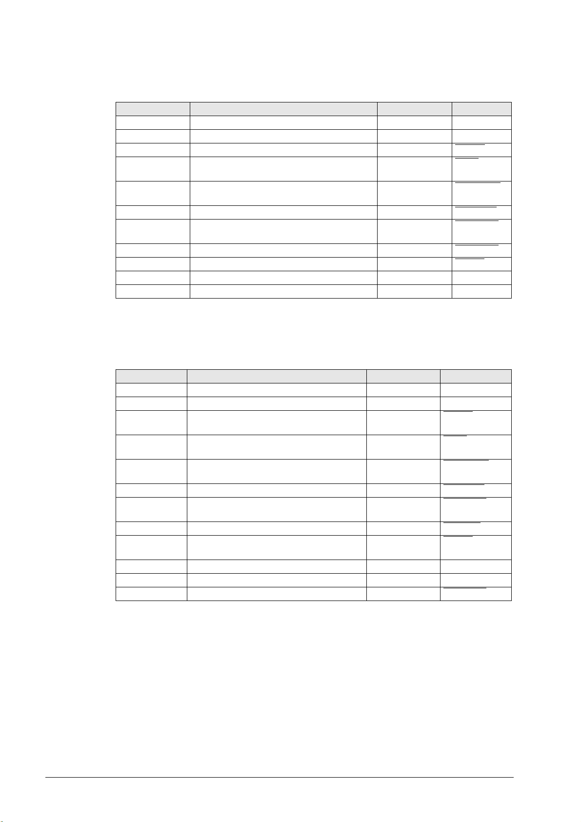
3.2 Overview of Possible Errors
The following table shows an overview of specific errors on the machine or control, possible
causes of the errors as well as measures for finding these errors.
The potential measures for finding and correcting the errors are described in more detail in the
corresponding chapters.
Error Error causes Measures for error diagnosis and/or
corrective action
The machine, for example, has failed
with a loud noise and cannot be
switched on again.
Ground fault or short circuit on a
device, cable, etc.
Grave defect of the motors or in the
inverter system
Check the fuses
Visual inspection
(scorch marks, humidity, severe
contamination, damages cable, etc.)
Is there a smell of burning?
Measure ground faults and short
circuits, see respective descriptions
in this manual
Replace inverters, motors, cables,
accessories that are obviously
defective
When hooking up axes, an
"overcurrent" error message is
generated
Motor coil fault
Short circuit in the motor cable
Short circuit in the voltage protection
module
Short circuit in the power module or
in the end stage
Check the motor for an interturn
fault --> See “Inspection for Winding
Short Circuit or Interruption” on
page 6 – 50
Check the motor for a short circuit
Check the voltage protection
module for a short circuit--> See
“Inspection for Short Circuit” on
page 8 – 155
Check power modules and end
stages for short circuits --> See
respective descriptions in this
manual
Replace inverters, motors, cables,
accessories that are obviously
defective
The control generates error messages
regarding the motor current (e.g., No
motor current, Motor current too high)
Motor defective
Motor cable defective
Inverter defective
Conductor bars for the dc-link not
tightened sufficiently
Check the motor --> See
“Troubleshooting on Motors” on
page 6 – 45
Check the motor for a short circuit
Check power modules and end
stages --> See respective
descriptions in this manual
Check the voltage protection
module for a short circuit--> See
“Inspection for Short Circuit” on
page 8 – 155
Tighten conductor bars with 3.5 Nm
Replace inverters, motors, cables,
accessories that are obviously
defective

June 2008 3 – 15
The machine is switched on but the
screen of the control remains dark.
Phase in the primary supply is
missing
Defective switch-mode power
supply in the power supply unit (UV,
UVR) or compact inverter (UE, UR)
Defective power supply unit
UV 105 B
Ribbon cable X69 defective
Defective 5V supply via terminal X74
Defective unit that is connected to
the control impairs the low voltages
Check the phases in the primary
supply
Check the function of the supply unit
or the compact inverter
Check the function of the UV 105 B
Check the ribbon cable X69
Check the 5V supply via terminal
X74
Disconnect suspicious units from
the control and deselect it in the
machine parameters --> see service
manual of the respective control
The dc-link voltage U
z
is not built up
(the screen of the control functions).
Phase in the primary supply is
missing
Interruption in the electrical cabinet,
safety relays are not released
Defective power supply unit (UV,
UVR) or compact inverter (UE, UR)
Defective capacitor module
Dc-link short circuit in the UM
Check the phases in the primary
supply
Check the releases for the safety
relays
Check the function of the supply unit
or the compact inverter
Replace the capacitor module
Measure short circuits, see
respective descriptions in this
manual
The message RELAY EXTERNAL DC
VOLTAGE MISSING does not disappear,
although the key "Control voltage ON"
is pressed.
EMERGENCY STOP chain
interrupted
24 Vdc power supply for outputs is
missing
Control defective
Check the EMERGENCY STOP
chain in the range of the inverter
connectors X70, X71, X72
See service manual of the
respective HEIDENHAIN control
Axes cannot be traversed. Drive release missing
Inverter system is not ready for
operation
See service manual of the
respective HEIDENHAIN control
Check whether the inverter system
is ready
Axes that are enabled via an axis-
release module, cannot be traversed.
Drive enable via axis group
connector X150, 151 on the CC is
missing
Axis-release module defective
Measure 24 V at X150, 151
Replace axis-release module
The monitor of an iTNC 530 is frozen.
The control has locked up.
The main switch has to be switched
off and on again.
After reset of the control"Power fail
Interrupt!" is entered in the log of
new software versions.
Power failure
Failure of one or several phases in
the supply line
The power supply voltage has fallen
below the minimum value
Interruption in the electrical cabinet
Defective power supply unit (UV,
UVR) or compact inverter (UE, UR)
Check the primary voltage
Check the fuses
Check the wiring of the inverter
system --> See circuit diagrams of
the machine manufacturer
Check the function of the supply unit
or the compact inverter
"Vibrating" axes, sometimes
connected with loud noises.
and/or
Various error messages are generated
which, however, are not substantive.
Poor shielding or grounding
Connection (short circuit) of
shielding potential (chassis, cable
shielding) with 0V voltage potential
of the NC power supply
Connectors on grounding terminal
X131 of infeed/regenerative module
(Simodrive 611D) not properly wired
Check the grounding of the machine
--> Consult the machine
manufacturer!
Ensure that all grounding clamps are
secure
Check the cables for damage.
Check the shieldings, covers, etc.
Check the groundIng in connection
with the used HEIDENHAIN
expansion boards, See “Error
Diagnosis on the Inverter System”
on page 7 – 67
Error Error causes Measures for error diagnosis and/or
corrective action

3 – 16 HEIDENHAIN Service Manual Inverter Systems and Motors
When braking axes and spindles, the
motors suddenly coast out of loop to a
stop.
Defective braking resistor
(conversion of electrical energy to
heat energy not possible)
Defective infeed/regenerative
feedback module (energy recovery
not possible)
Interruption in the primary supply
(fuses, wires, etc.; energy recovery
not possible)
Measure braking resistor, See
“Error Diagnosis on the PW Braking
Resistor” on page 8 – 140
Check the fuses
Wiring interrupted
--> See circuit diagrams of the
machine manufacturer
Check the function of the supply unit
or the compact inverter
An axis is traversed and the error
message I2T value of motor is too
high ... is displayed (or a similar error
message that indicates an excessive
load of the drive).
There is no mechanical damage!
Motor brake not released. Check whether the brake is released
Check the wiring of the motor
system --> See circuit diagrams of
the machine manufacturer.
If the motor brake is connected to
the inverter module -->
Check whether the brake output is
supplied and triggered correctly.
SIMODRIVE system used with CC 422
The control can be switched on.
During operation the power module
always transmits the Ready signal.
The signal reporting that the power
module is no longer ready is not
detected in some cases.
"Old" HEIDENHAIN expansion board
in modified SIMODRIVE power
module
Check the constellation
HEIDENHAIN expansion board and
SIMODRIVE power module. See
“Compatibility of HEIDENHAIN
expansion boards to SIMODRIVE
power modules” on page 3 – 22
SIMODRIVE system used with CC 424
(B):
After power on, the power module
transmits a "Ready" signal to the control
although the power module is not
ready yet. The control reports the error
C510 Impermissible drive enable and
cannot be put into operation.
"Old" HEIDENHAIN expansion board
in modified SIMODRIVE power
module
Check the constellation
HEIDENHAIN expansion board and
SIMODRIVE power module. See
“Compatibility of HEIDENHAIN
expansion boards to SIMODRIVE
power modules” on page 3 – 22
SIMODRIVE system used with TNC
426 PB and TNC 430 PA:
After the power module has been
switched on, it constantly reports that
it is ready, even if this is not the case.
In certain situations the “Drives not
ready” message can appear, even
though it may no longer even be
possible to switch the drives on.
"Old" HEIDENHAIN expansion board
in modified SIMODRIVE power
module
Check the constellation
HEIDENHAIN expansion board and
SIMODRIVE power module. See
“Compatibility of HEIDENHAIN
expansion boards to SIMODRIVE
power modules” on page 3 – 22
Error Error causes Measures for error diagnosis and/or
corrective action
June 2008 3 – 17
3.3 Important Notes on the Use of HEIDENHAIN Expansion Boards in the
SIMODRIVE System
Version with
D-sub connector
HEIDENHAIN expansion boards for the SIMODRIVE system in the version with D-Sub connector
are available with or without metallic insulation of HEIDENHAIN PWM signals to the Siemens
interface.
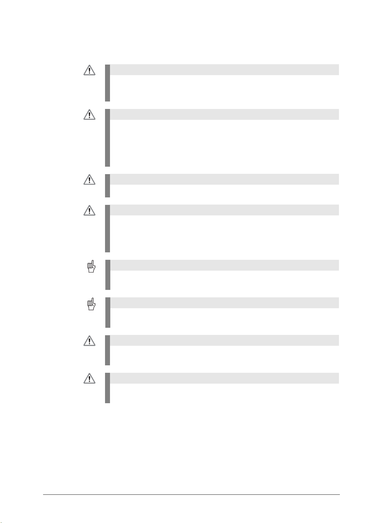
Expansion boards without metallic insulation are
recognized as follows:
On the front panel there are the LEDs NB (not ready) and
IF (pulse release).
There is no grounding screw on the front panel.
There is no transformer on the front panel.
These board have the Id.Nr. 291070-01, 324952-01, -02, -
03 and -10 without index A.
Caution
The terminal X131 of the Siemens E/R module of boards without metallic insulation
may not be connected to the central signal ground of the machine!
Note
The HEIDENHAIN expansion boards of the first generation were built without metallic
insulation.
3 – 18 HEIDENHAIN Service Manual Inverter Systems and Motors
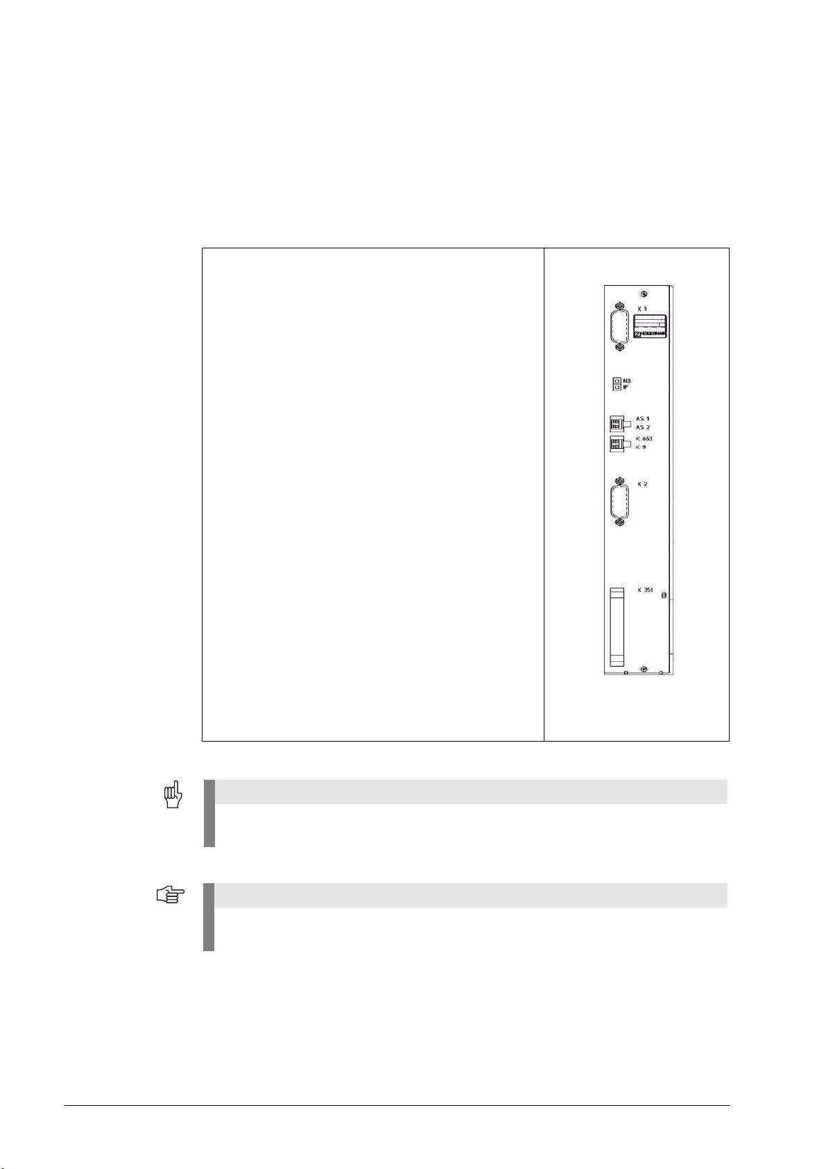
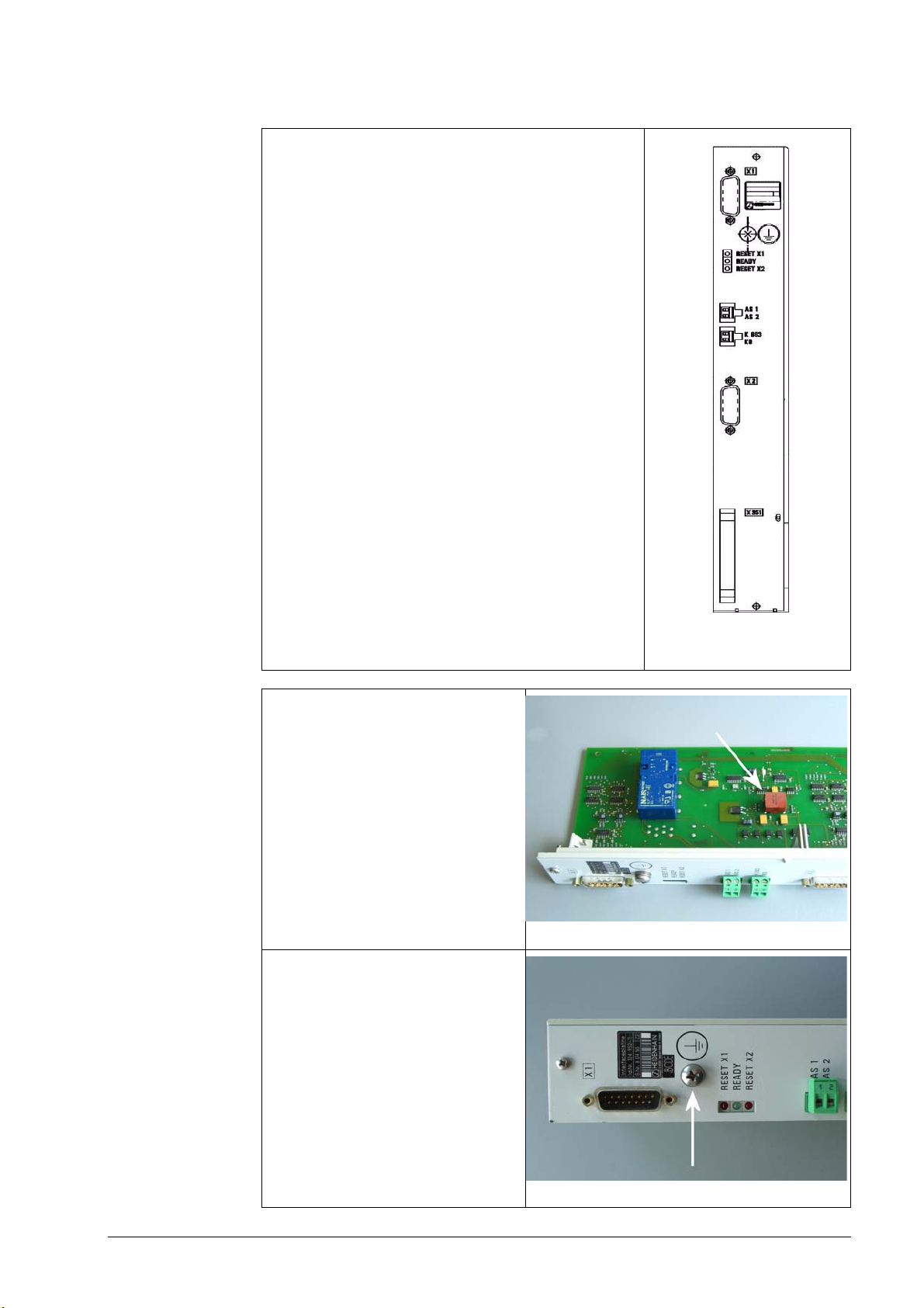
Expansion boards with metallic insulation are recognized
as follows:
On the front panel there are the LEDs RESET X1, READY
and RESET X2.
There is a grounding screw on the front panel.
There is a transformer on the front panel.
These boards have the Id.Nr. 324952-10 with index A, -11,
-12, ...
Transformer component on the board
Grounding screw on the front panel

June 2008 3 – 19
Photo: Siemens E/R module with X131
Caution
The terminal X131 of the Siemens E/R module of boards with metallic insulation
must be connected to the central signal ground of the machine!
Caution
Expansion boards with and without metallic insulation may not be used together!
Either all boards have a metallic insulation and X131 is wired or all boards do not have a
metallic insulation and X131 is not wired!
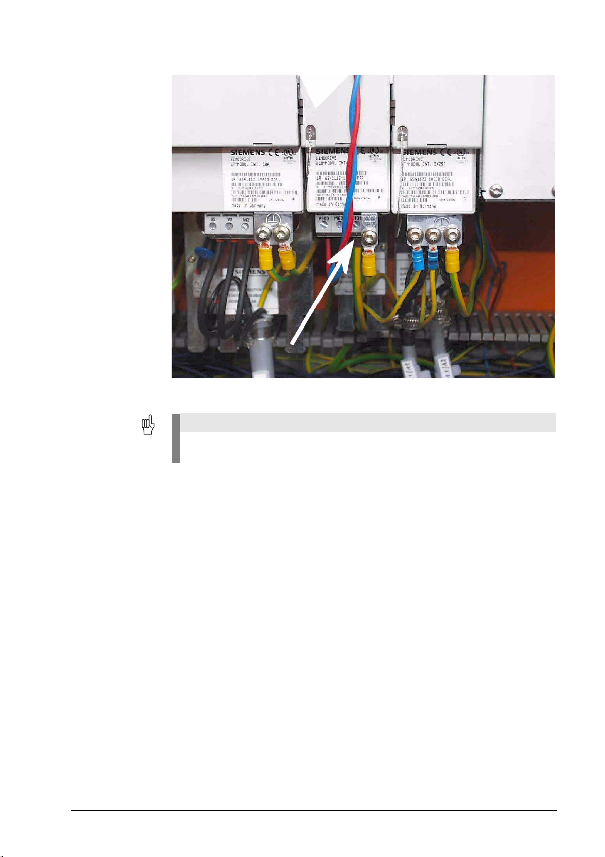
3 – 20 HEIDENHAIN Service Manual Inverter Systems and Motors
Photo: Siemens UEB module with X131
Caution
If a Siemens E/R module is used together with a so-called monitoring module (UEB module),
the terminal X131 on this module has to be wired as on the E/R module!
June 2008 3 – 21
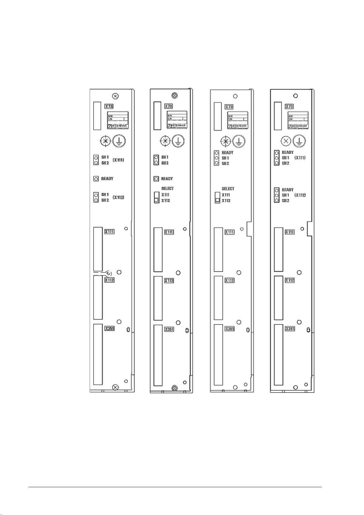
Version with ribbon
cable connector
HEIDENHAIN expansion boards for the SIMODRIVE system in the version with ribbon cable
have a metallic insulation of the HEIDENHAIN PWM signals to the Siemens interface.
Thus X131 of the Siemens drive system must be wired!
Figure: Various HEIDENHAIN expansion boards with ribbon cable connectors
3 – 22 HEIDENHAIN Service Manual Inverter Systems and Motors
Compatibility of
HEIDENHAIN
expansion boards
to SIMODRIVE
power modules
SIEMENS has already improved the SIMODRIVE power modules.
Among other things the interference suppression circuits have been supplemented.
The HEIDENHAIN expansion boards suitable for the modified SIMODRIVE power modules have
also been improved:
The HEIDENHAIN expansion boards listed in the above table, replace the previous variants.
This means that they may also be inserted in "older" SIMODRIVE power modules.
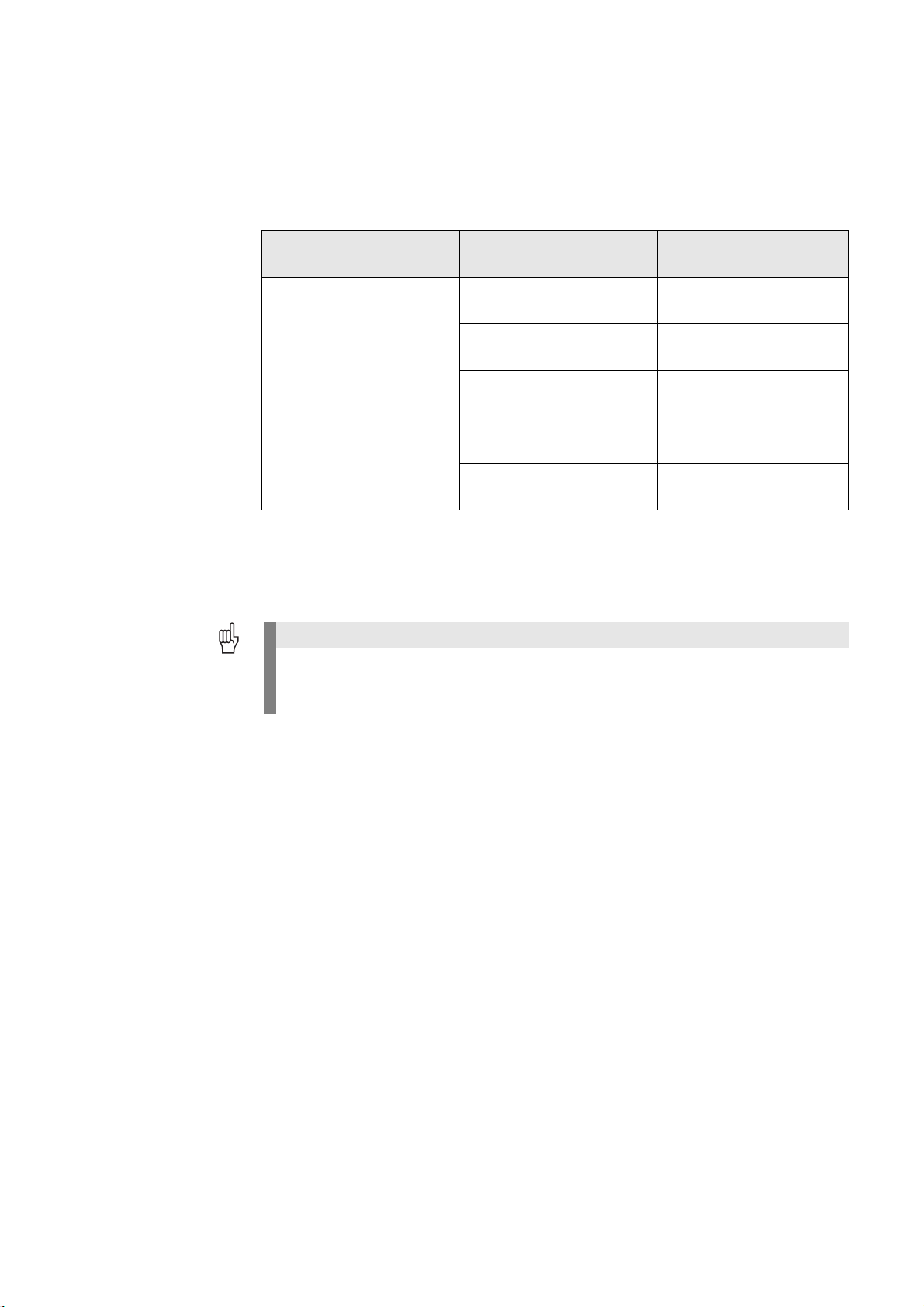
Modified SIMODRIVE
power modules
Suitable HEIDENHAIN
expansion boards
Design
At the end of the SIEMENS
ordering designation of the
improved power modules
you find the code A2 or A3.
324952-03, index A 2-axis version,
D-sub connector
324952-12, index D 2-axis version,
D-sub connector
324955-17 1-axis version,
ribbon-cable connector
359002-05 2-axis version,
ribbon-cable connector
515012-03 1-axis version,
ribbon-cable connector
Caution
"Older" HEIDENHAIN expansion boards may not be operated with modified SIMODRIVE
power modules.
Possible errors and error messages --> See “Overview of Possible Errors” on page 3 – 14
June 2008 3 – 23
3.4 Error Messages on the Monitor of the Control
HEIDENHAIN inverter systems and HEIDENHAIN motors are usually operated with
HEIDENHAIN controls.
Errors on inverters and/or motor that occur when the machine is switched on or during operation
are ideally shown as errors on the monitor. The operator or the service engineer obtains
information on the possible causes of the error and on corrective action. In case of axis-specific
errors, there is an axis symbol (e.g. X) in the error text!
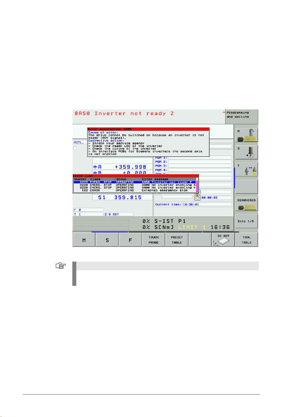
Example of an NC error message on the monitor of an iTNC 530:
List of NC error
messages
HEIDENHAIN has defined NC error messages. You can find the complete list of all NC error
messages for TNC controls on the TNCguide DVD in several languages and sorted by error
numbers. You find this TNCguide information on our website www.heidenhain.de.
PLC error messages In addition to the NC error messages defined by HEIDENHAIN, the machine manufacturer can
define PLC error messages.
The manufacturer can define the machine behavior in case of a PLC error (NC stop,
EMERGENCY STOP, etc.). The machine can thus be protected additionally. The operator or the
service engineer obtains machine-specific information on the possible causes of the error and
on corrective action together with PLC error messages.
Note
If it is possible and makes sense, you may switch the control off and on again to observe
whether the error message is generated again afterwards.

3 – 24 HEIDENHAIN Service Manual Inverter Systems and Motors
Example of an PLC error message on the monitor of an iTNC 530:
Log HEIDENHAIN controls feature a log. Information on key strokes, error messages etc. are
recorded in these logs.
You will find information in the respective service manuals of the controls (e.g. SHB iTNC 530)!
Example of NC error messages in the log of an iTNC 530:

June 2008 4 – 25
4 Explanation of the LEDs
4.1 Compact Inverters
On the front of the compact inverters are several LEDs for functional control, with the following
meaning:
UE 1xx
UE 2xx
LED Meaning Signal direction Signal
U
DC LINK ON
Main contactor triggered – –
SH1 (RED)
RDY (GREEN)
Safe stop 1; no enable from control (main
contactor not active, DSP error, PLC error
with EMERGENCY STOP, hardware or
software error of LE, CC)
Axis/spindle enabled
LE, CC → UE
UE → LE, CC
SH1B
RDY
SH2 Safe stop 2; no drive enable from control
(e.g. by the PLC, active via external signal or
SH1)
LE, CC → UE SH2
PWR RESET Reset signal from UE to LE, CC UE → LE, CC RES.PS
READY Inverter ready UE → LE, CC RDY
U
DC LINK
>> U
Z
too high (> approx. 850 V); power
modules are switched off
UE → LE, CC ERR.UZ.GR
PWR FAIL U
Z
too low, U
Z
< 410 V (e.g. failure of a
phase under load, power < 290 V)
UE → LE, CC PF.PS
NC reset Reset signal from LE, CC to UE LE, CC → UE RES.LE
TEMP >> Temperature of heat sink too high (> 100 °C) UE → LE, CC ERR.TEMP
X 71 SP. Safety relay for spindle triggered – –
X 72 AXES Safety relay for axes triggered – –
LED Meaning Signal direction Signal
U
DC LINK ON
Main contactor triggered – –
+ 5 V + 5 V power supply available – –
U
DC LINK
>> U
Z
too high (> approx. 800 V); power
modules are switched off
UE → LE, CC ERR.UZ.GR
TEMP >> Temperature of heat sink too high (> 100 °C) UE → LE, CC ERR.TEMP
AXIS FAULT Short circuit between a phase of the motor
output and U
Z
(axes only)
UE → LE, CC AXISFAULT
POWER FAIL U
Z
too low, U
Z
< 410 V (e.g. failure of a
phase under load, power < 290 V)
UE → LE, CC PF.PS
POWER RESET Reset signal from UE to LE UE → LE, CC RES.PS
AXIS/SPINDLE
RESET
Axes/spindle disabled by LE LE, CC → UE SH2
AXIS/SPINDLE
READY
Inverter ready UE → LE, CC RDY
PULSE RELEASE
SPINDLE
Safety relay for spindle triggered – –
PULSE RELEASE
AXES
Safety relay for axes triggered – –

4 – 26 HEIDENHAIN Service Manual Inverter Systems and Motors
UE 2xxB
UR 2xx
UR 2xx D
LED Meaning Signal direction Signal
U
DC LINK ON
Main contactor triggered – –
X11x READY Inverter ready UE → LE, CC RDY
X11x SH1 DSP error, PLC error with emergency stop,
LE hardware or software error
LE, CC → UE SH1B
X11x SH2 No drive enable (e.g. by the PLC, active via
external signal or SH1)
LE, CC → UE SH2
READY Inverter ready UE → LE, CC RDY
POWER RESET Reset signal from UE to LE UE → LE, CC RES.PS
POWER FAIL U
Z
too low, U
Z
< 410 V (e.g. failure of a
phase under load, power < 290 V)
UE → LE, CC PF.PS
U
DC LINK
>> U
Z
too high (> approx. 800 V); power
modules are switched off
UE → LE, CC ERR.UZ.GR
TEMP >>
(left)
Heat sink temperature too high for axis 4 and
spindle (> 100 °C)
UE → LE, CC ERR
TEMP >>
(right)
Heat sink temperature too high for axis 1 to
axis 3 (> 100 °C)
UE → LE, CC ERR
NC reset Reset signal from the LE to the UE LE, CC → UE RES.LE
PULSE RELEASE
SPINDLE
Safety relay for spindle triggered – –
PULSE RELEASE
AXES
Safety relay for axes triggered – –
LED Meaning Signal direction Signal
U
DC LINK ON
Main contactor triggered – –
X11x READY Inverter ready UR → LE, CC RDY
X11x SH1 DSP error, PLC error with Emergency Stop,
LE hardware or software error
LE, CC → UR SH1B
X11x SH2 No drive enable (e.g. by the PLC, active via
external signal or SH1)
LE, CC → UR SH2
READY UV Inverter ready UR → LE, CC RDY
POWER RESET Reset signal from UR to LE UR → LE, CC RES.PS
POWER FAIL U
Z
too low, U
Z
< 410 V (because the main
contactor is off, for example)
UR → LE, CC PF.PS
U
DC LINK
>> U
Z
too high (> approx. 800 V); power
modules are switched off
UR → LE, CC ERR.UZ.GR
I
DC LINK
>> I
Z
> 52 A,
warning signal to control at 58 A
UR → LE, CC ERR.IZ.GR
I
LEAK
>> Error current, e.g. through ground fault;
warning signal to control
UR → LE, CC ERR.ILEAK
TEMP >>
(left)
Heat sink temperature too high for axis 4 and
spindle (> 100 °C)
UR → LE, CC ERR
TEMP >>
(right)
Heat sink temperature too high for axis 1 to
axis 3 (> 100 °C)
UR → LE, CC ERR
AC FAIL Phase missing UR → LE, CC PF.PS.AC
NC reset Reset signal from the LE to the UR 2xx LE, CC → UR RES.LE
AXES Safety relay for axes triggered – –
SPINDLE Safety relay for spindle triggered – –

June 2008 4 – 27
Red LED SH1 The SH1 signal (safe stop 1, red LED at the inverter) is generated by the main computer (MC) of
the HEIDENHAIN control. The signal is low-active, i.e. line-break proof.
If the main computer is not ready for operation or if an error is pending, SH1 is output. The red
SH1 LED and the green READY LED at the inverter can never be lit at the same time. They are
mutually locked.
Red LED SH2 The SH2 signal (safe stop 2, red LED at the inverter) is generated by the controller computer (CC)
of the HEIDENHAIN control.
The signal is low-active, i.e. line-break proof.
If an axis or spindle is not controlled, SH2 is pending and the red LED is on.
This is for example the case with clamped axes or if a spindle is not controlled.
SH2 and READY are on simultaneously.

4 – 28 HEIDENHAIN Service Manual Inverter Systems and Motors
4.2 Power supply units
UV 120,
UVR 120D,
UVR 130D,
UV 140,
UVR 140D,
UV 150,
UVR 150,
UVR 150D,
UVR 160D,
UVR 160DW
LED Meaning Signal direction Signal
READY End stage ready (only for service purposes) – –
RESET Reset for end stage (only for service
purposes)
––
TEMP >> Temperature of heat sink too high (> 95 °C) UV → LE, CC ERR.TEMP
U
DC LINK ON
Main contactor triggered – –
READY UV Power supply unit is ready UV → LE, CC RDY.PS
POWER RESET Reset signal from power supply unit to
control
UV → LE, CC RES.PS
POWER FAIL U
Z
too low, U
Z
< 410 V (e.g. line power < 290
V)
UV → LE, CC PF.PS
U
DC LINK
>> U
Z
too high (> approx. 800 V); power
modules are switched off
UV → LE, CC ERR.UZ.GR
I
DC LINK
>> Warning signal to control at overcurrent.
UV 120: I
Z
> 52 A
a
UVR 120D: I
Z
> 52.5 A
UVR 130D: I
Z
> 71 A
UV 140: I
Z
> 103 A
UVR 140D: I
Z
> 105 A
UV 150: I
Z
> 119.0 A
UV 150: I
Z
> 103 A
UVR 150D: I
Z
> 126 A
UVR 160D: I
Z
> 126 A
UVR 160DW: I
Z
> 126 A
UV → LE, CC ERR.IZ.GR
I
LEAK
>> Error current, e.g. through ground fault;
warning signal to control
UV → LE, CC ERR.ILEAK
AC FAIL Phase missing UV → LE, CC PF.PS.AC
NC reset Reset signal from control to power supply
unit
LE, CC → UV RES.LE
AXES Safety relay for axes triggered – –
SPINDLE Safety relay for spindle triggered – –
a. A further increase of around 10% results in the drives being switched off.
This also applies for the other stated dc-link currents of the power supply units.
June 2008 4 – 29
UV 130
UV 130D
LED Meaning Signal direction Signal
U
DC LINK ON
Main contactor triggered – –
READY Power supply unit is ready UV → LE, CC RDY.PS
POWER RESET Reset signal from power supply unit to control UV → LE, CC RES.PS
POWER FAIL U
Z
too low, U
Z
< 410 V
(e.g. line power < 290 V)
UV → LE, CC PF.PS
U
DC LINK
>> U
Z
too high (> approx. 760 V); power modules
are switched off
UV → LE, CC ERR.UZ.GR
I
DC LINK
>> Warning signal to control at I
Z
> 75 A
a
UV → LE, CC ERR.IZ.GR
I
LEAK
>> Error current, e.g. through ground fault;
warning signal to control
UV → LE, CC ERR.ILEAK
TEMP >> Temperature of heat sink too high (> 95 °C) UV → LE, CC ERR.TEMP
NC reset Reset signal from control to power supply unit LE, CC → UV RES.LE
SPINDLE Safety relay for spindle triggered – –
AXES Safety relay for axes triggered – –
a. A further increase of around 10% results in the drives being switched off.
LED Meaning Signal direction Signal
U
DC LINK ON
Main contactor triggered – –
READY UV Power supply unit is ready UV → LE, CC RDY.PS
POWER RESET Reset signal from power supply unit to
control
UV → LE, CC RES.PS
POWER FAIL U
Z
too low, U
Z
< 410 V
(e.g. line power < 290 V)
UV → LE, CC PF.PS
U
DC LINK
>> U
Z
too high (> approx. 800 V); power
modules are switched off
UV → LE, CC ERR.UZ.GR
I
DC LINK
>> Warning signal to control at I
Z
> 85.2 A
a
UV → LE, CC ERR.IZ.GR
I
LEAK
>> Error current, e.g. through ground fault;
warning signal to control
UV → LE, CC ERR.ILEAK
AC FAIL Phase missing UV → LE, CC PF.PS.AC
NC reset Reset signal from control to power supply
unit
LE, CC → UV RES.LE
AXES Safety relay for axes triggered – –
SPINDLE Safety relay for spindle triggered – –
TEMP >> Temperature of heat sink too high (> 95 °C) UV → LE, CC ERR.TEMP
a. A further increase of around 10% results in the drives being switched off.

4 – 30 HEIDENHAIN Service Manual Inverter Systems and Motors
4.3 Power Modules
UM 1xx
Red SH1 LED The SH1 signal (safe stop 1, red LED at the inverter) is generated by the main computer (MC) of
the HEIDENHAIN control. The signal is low-active, i.e. line-break proof.
If the main computer is not ready for operation or if an error is pending, SH1 is output. The red
SH1 LED and the green READY LED at the inverter can never be lit at the same time. They are
mutually locked.
Red SH2 LED The SH2 signal (safe stop 2, red LED at the inverter) is generated by the controller computer (CC)
of the HEIDENHAIN control.
The signal is low-active, i.e. line-break proof.
If an axis or spindle is not controlled, SH2 is pending and the red LED is on.
This is for example the case with clamped axes or if a spindle is not controlled.
SH2 and READY are on simultaneously.
LED Meaning Signal direction Signal
READY Power module is ready UM → LE, CC RDY
SH 1 DSP error, PLC error with Emergency Stop, LE
hardware or software error
LE, CC → UM SH1
SH 2 No drive enable (e.g. by the PLC, active via
external signal or SH1)
LE, CC → UM SH2
TEMP >> Warning signal for IGBT temperature too high UM → LE, CC ERR
Loading...