


MICOM-2ES/2RS/2TS ALE
HF-SSB TRANSCEIVERS Support for MIL-STD-188-141B
Supplement to Owner’s Guide
|
|
|
|
IMRMB008 |
best radio for worst events |
||||
COMMERCIAL WARRANTY (STANDARD)
Motorola radio communications products are warranted to be free from defects in material and workmanship for a period of ONE (1) YEAR, (except for crystals and channel elements which are warranted for a period of ten (10) years) from the date of shipment. Parts, including crystals and channel elements, will be replaced free of charge for the full warranty period but the labor to replace detective parts will only be provided for One Hundred-Twenty (120) days from the date of shipment. Thereafter purchaser must pay for the labor involved in repairing the product or replacing the parts at the prevailing rates together with any transportation charges to or from the place where warranty service is provided. This express warranty is extended by Motorola Communications and Electronics Inc., 1301 E. Algonquin Road, Schaumburg, Illinois 60196, to the original purchaser only, and only to those purchasing for purpose of leasing or solely for commercial, industrial, or governmental use.
THIS WARRANTY IS GIVEN IN LIEU OF ALL OTHER WARRANTIES EXPRESS OR IMPLIED WHICH ARE SPECIFICALLY EXCLUDED, INCLUDING WARRANTIES OF MERCHANTABILITY OR FITNESS FOR A PARTICULAR PURPOSE. IN NO EVENT SHALL MOTOROLA BE LIABLE FOR INCIDENTAL OR CONSEQUENTIAL DAMAGES TO THE FULL EXTENT SUCH MAY BE DISCLAIMED BY LAW.
In the event of a defect, malfunction or failure to conform to specifications established by Seller, or if appropriate, to specifications accepted by Seller in writing, during the period shown. Motorola, at its option, will either repair or replace the product or refund the purchase price thereof, and such action on the part of Motorola shall be the full extent of Motorola's liability hereunder.
This warranty is void if:
a.The product is used in other than its normal and customary manner.
b.The product has been subject to misuse, accident, neglect or damage.
c.Unauthorized alterations or repairs have been made, or unapproved parts used in the equipment.
This warranty extends only to individual products, batteries are excluded, but carry their own separate limited warranty. Because each radio system is unique, Motorola disclaims liability for range, coverage, or operation of the system as a whole under this warranty except by a separate written agreement signed by an officer of Motorola.
Non-Motorola manufactured products are excluded from this warranty, but subject to the warranty provided by their manufacturers, a copy of which will be supplied to you on specific written request.
To obtain performance of this warranty, purchaser must contact:
Phone: (850)580-7816
Fax: (850)576-8421
This warranty applies only within the United States.
COMPUTER SOFTWARE COPYRIGHTS
The Motorola products described in this instruction manual may include copyrighted Motorola computer programs stored in semiconductor memories or other media. Laws in the United States and other countries preserve for Motorola certain exclusive rights for copyrighted computer programs, including the exclusive right to copy or reproduce in any form the copyrighted computer program. Accordingly, any copyrighted Motorola computer programs contained in the Motorola products described in this instruction manual may not be copied or reproduced in any manner without the express written permission of Motorola. Furthermore, the purchase of Motorola products shall not be deemed to grant either directly or by implication, estoppel, or otherwise, any license under the copyrights, patents or patent applications of Motorola, except for the normal non-exclusive, royalty free license to use that arises by operation of law in the sale of a product.

best radio for worst events
MICOM-2ES/2RS/2TS ALE HF-SSB TRANSCEIVER
ALE Support for MIL-STD-188-141B
Motorola |
Supplement to |
1720 West Paul Dirac Drive, |
Owner’s Guide |
Tallahassee 32310 FL, USA |
|
|
Cat. No. IMRMB008 |
Warnings, Cautions and Notes
Warnings, Cautions and Notes
The following notations are used to place special emphasis on procedures, or to call attention to precautionary measures.
An operating procedure, practice and so forth, which if not followed correctly, could result in personal injury, or loss of life.
Warning
An operating procedure, practice and so forth, which if not followed correctly, could result in damage to, or destruction of equipment.
Important
An operating procedure, condition and so forth, to which special attention should be paid.
Note
General Safety Precautions
The following are general safety precautions that are not related to any specific procedures and therefore do not appear elsewhere in this publication. These are recommended precautions that personnel must understand and apply, in addition to the precautions listed in the Information for Safe, Efficient Operation section.
Warning
High
Voltage
Do not touch the antenna and the RF connectors when the transceiver operates.
During transmission, high RF voltages appear at the RF connectors, the antenna cables, and on the antenna itself. These voltages may cause severe injury or even death on contact.
Operating and maintenance personnel must be familiar with the applicable safety requirements before attempting to install or operate the transceiver. Severe injury or death could result from failure to comply with the safety practices.
_________________________________________________________________________________________________ i

MICOM-2ES/2RS/2TS ALE Supplement to Owner’s Guide
Information for Safe, Efficient Operation
Product Safety and RF Exposure for Mobile Two-Way Radios Installed in Vehicles or as Fixed Site Control Stations
BEFORE USING THIS RADIO, READ THIS BOOKLET WHICH CONTAINS IMPORTANT OPERATING INSTRUCTIONS FOR SAFE USAGE AND RF ENERGY AWARENESS AND CONTROL
INFORMATION FOR COMPLIANCE WITH RF ENERGY
Caution EXPOSURE LIMITS IN APPLICABLE NATIONAL AND INTERNATIONAL STANDARDS.
The information provided in this document supersedes the general safety information contained in user guides published prior to February 2002.
Compliance with RF Energy Exposure Standards
NOTICE |
This radio is intended for use in occupational/controlled |
|
applications where users have been made aware of the potential |
|
for exposure and can exercise control over their exposure. This |
|
radio device is NOT authorized for general population, |
|
consumer or similar use. |
Motorola, Inc. 2003
8000 W. Sunrise Blvd., Ft. Lauderdale, FL 33322
Printed in USA. 7/03
ii ________________________________________________________________________________________________

Warnings, Cautions and Notes
Federal Communication Commission Regulations
The FCC has established limits for safe exposure to radio frequency (RF) emissions from mobile two-way radios. The FCC requires manufacturers to demonstrate compliance with RF exposure limits before mobile two-way radios can be marketed In the U.S. When two-way radios are approved for occupational/controlled environment exposure limits, the FCC requires users to be fully aware of, and exercise control over, their exposure. Awareness and control of RF exposure can be accomplished by education or training through appropriate means such as information and instructions in user manuals or safety booklets, or other appropriate means. This user safety booklet includes useful information about RF exposure and helpful instructions on how to control your RF exposure.
Your Motorola two-way radio is designed and tested to comply with a number of national and international standards and guidelines (listed below) regarding human exposure to radio frequency electromagnetic energy. This radio complies with the
IEEE (FCC) and ICNIRP exposure limits for occupational/controlled RF exposure environments at usage factors of up to 50% talk-50% listen. In terms of measuring RF energy for compliance with FCC exposure guidelines, your radio radiates measurable RF energy only while it is transmitting (during talking), not when it is receiving (listening) or in standby mode.
Your Motorola two-way radio complies with the following RF energy exposure standards and guidelines:
•United States Federal Communications Commission, Code of Federal Regulations; 47CFR part 2 sub-part J
•American National Standards Institute (ANSI) / Institute of Electrical and Electronic Engineers (IEEE) C95.1-1992
•Institute of Electrical and Electronic Engineers (IEEE) C95.1-1999 Edition
•International Commission on Non-Ionizing Radiation Protection (ICNIRP) 1998
•Ministry of Health (Canada) Safety Code 6: Limits of Human Exposure to Radiofrequency Electromagnetic Fields in the Frequency Range from 3 kHz to 300 GHz, 1999
•Australian Communications Authority Radiocommunications (Electromagnetic Radiation – Human Exposure) Standard, 2001
•ANATEL, Brasil Regulatory Authority, Resolution 256 (April 11, 2001). Additional Requirements for SMR, Cellular and PCS Product Certification.
_________________________________________________________________________________________________ iii

MICOM-2ES/2RS/2TS ALE Supplement to Owner’s Guide
Compliance and Control Guidelines and Operating Instructions for Mobile Two-Way Radios Installed in Vehicles
To control your exposure and ensure compliance with the occupational/controlled environment exposure limits, always adhere to the following procedures:
•To transmit (talk), push the Push-To-Talk (PTT) button; to receive, release the PTT button. Transmit only when people outside the vehicle are at least 7 feet from a properly installed, externally-mounted antenna.
•Install mobile antennas at the center of the roof or the center of the trunk deck per specific guidelines and instructions in the Radio Installation Manual. These mobile antenna installation guidelines are limited to metal body vehicles.
Use only the Motorola-approved, supplied antenna or a Motorolaapproved replacement antenna. Use of non-Motorola-approved antennas, modifications, or attachments could damage the radio and may violate FCC regulations.
Compliance and Control Guidelines and Operating Instructions for Mobile Two-Way Radios Installed as Fixed Site Control Stations
If mobile radio equipment is installed at a fixed location and operated as a control station or as a fixed unit, the antenna installation must comply with the following requirements in order to ensure optimal performance and compliance with the RF energy exposure limits in the standards and guidelines listed in the Federal Communication Commission Regulations section.
•The antenna should be mounted outside the building on the roof or a tower if at all possible.
•As with all fixed site antenna installations, it is the responsibility of the licensee to manage the site in accordance with applicable regulatory requirements and may require additional compliance actions such as site survey measurements, signage, and site access restrictions in order to ensure that exposure limits are not exceeded.
iv ________________________________________________________________________________________________
Warnings, Cautions and Notes
Electromagnetic Interference/Compatibility
Note
Facilities
Nearly every electronic device is susceptible to electromagnetic interference (EMI) if inadequately shielded, designed, or otherwise configured for electromagnetic compatibility. It may be necessary to conduct compatibility testing to determine if any electronic equipment used in or around vehicles or near fixed site antenna is sensitive to external RF energy or if any procedures need to be followed to eliminate or mitigate the potential for interaction between the radio transmitter and the equipment or device.
To avoid electromagnetic interference and/or compatibility conflicts, turn off your radio in any facility where posted notices instruct you to do so. Hospitals or health care facilities may be using equipment that is sensitive to external RF energy.
Vehicles
To avoid possible interaction between the radio transmitter and any vehicle electronic control modules, for example, ABS, engine, or transmission controls, the radio should be installed only by an experienced installer and that the following precautions be used when installing the radio:
1.Refer to the manufacturer's instructions or other technical bulletins for recommendations on radio installation.
2.Before installing the radio, determine the location of the electronic control modules and their harnesses in the vehicle.
3.Route all radio wiring, including the antenna transmission line, as far away as possible from the electronic control units and associated wiring.
Driver Safety
Check the laws and regulations on the use of radios in the area where you drive. Always obey them.
When using your radio while driving, please:
•Give full attention to driving and to the road.
•Pull off the road and park before making or answering a call if driving conditions so require.
_________________________________________________________________________________________________ v
MICOM-2ES/2RS/2TS ALE Supplement to Owner’s Guide
Operational Warnings
Warning
Warning
For Vehicles with an Air Bag
Do not mount or place a mobile radio in the area over an air bag deployment area. Air bags inflate with great force. If a radio Is placed in the air bag deployment area and the air bag inflates, the radio may be propelled with great force and cause serious injury to occupants of the vehicle.
Potentially Explosive Atmospheres
Turn off your radio prior to entering any area with a potentially explosive atmosphere. Sparks in a potentially explosive atmosphere can cause an explosion or fire resulting in bodily injury or even death.
The areas with potentially explosive atmospheres include fueling areas such as below decks on boats, fuel or chemical transfer or storage facilities, and areas where the air contains chemicals or particles such as grain, dust or metal powders. Areas with potentially explosive atmospheres are often, but not always, posted.
Blasting Caps and Blasting Areas
To avoid possible interference with blasting operations, turn off warning your radio when you are near electrical blasting caps, in a blasting area, or in areas posted: "Turn off twoway radio". Obey all signs and instructions.
For radios installed in vehicles fueled by liquefied petroleum gas, refer to the (U.S.) National Fire Protection Association standard, NFPA 58, for storage, handling, and/or container information. For a copy of the LP-gas standard, NFPA 58, contact the National Fire Protection Association, One Battery Park, Quincy, MA.
vi ________________________________________________________________________________________________

|
Table of Contents |
Table of Contents |
|
|
Page |
Introduction .................................................................................................... |
1 |
Menu Updates................................................................................................. |
1 |
New ALE Features ......................................................................................... |
6 |
Selective Calling ....................................................................................... |
6 |
ALE Addressing Method .......................................................................... |
6 |
Address and Call Types ............................................................................ |
7 |
Using ALE Functions in the Channel Mode ............................................. |
13 |
Entering the ALE Mode............................................................................ |
14 |
Receiving and Transmitting Calls in ALE Mode...................................... |
16 |
ALE Programming ......................................................................................... |
53 |
Programming Nets .................................................................................... |
54 |
Setting the Net Options ............................................................................. |
57 |
Directory Parameters................................................................................. |
58 |
AMD Message Configuration................................................................... |
58 |
ALE Options Configuration...................................................................... |
59 |
Auto Dial Parameters ................................................................................ |
61 |
Storing ALE Parameters ........................................................................... |
61 |
Using the New Station Address Filter....................................................... |
62 |
_________________________________________________________________________________________________ vii

MICOM-2ES/2RS/2TS ALE Supplement to Owner’s Guide
viii ________________________________________________________________________________________________
Introduction
Introduction
This Supplement to the “MICOM-2E/2R ALE HF-SSB Transceivers Owner’s Guide”, Publication 68P02952C60-A, provides you with information on the full support for ALE in accordance with the MIL-STD-188-141B (previous versions supported only MIL-STD-188-141A).
This new feature is available only on new versions (Version CK) of the MICOM-2E/2RS/2TS ALE HF-SSB transceivers (which are described in the “Supplement to Owner’s Guide”, Publication 6886872J01).
The information appearing in this Supplement is intended for use with the “Owner’s Guide, MICOM-2E/2RS/2TS ALE HF-SSB Transceivers”, Publication 68P02952C60-A, together with the “Supplement to Owner’s Guide”, Publication 6886872J01.
Menu Updates
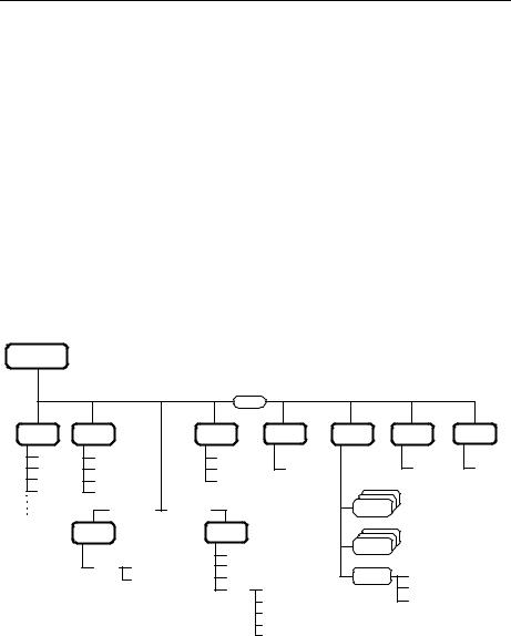
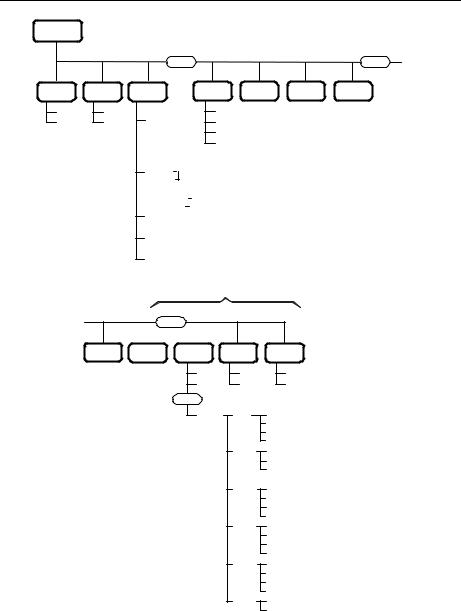
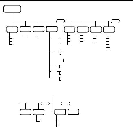
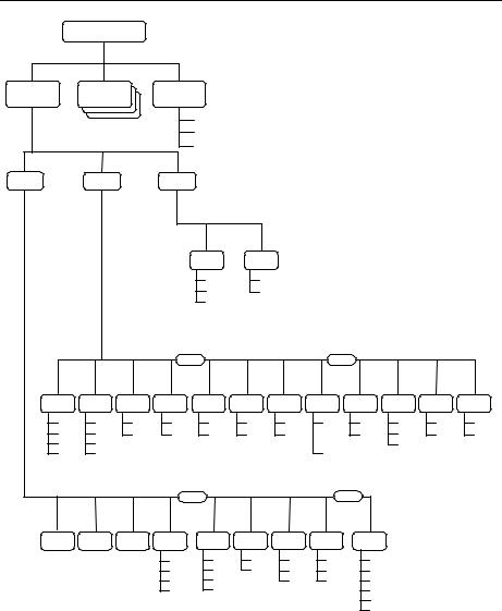
Figure 1 through Figure 5 present the new MICOM-2 menus.
Main Menu
MORE
CHAN |
FREQ |
BIT |
LOCK |
PROG |
PSW |
DIM |
1 |
SMPX |
FULL |
|
|
|
|
2 |
DPLX |
CHAN |
LOCK |
|
PSW |
LEVEL |
3 |
RXO |
L.RF |
PSW |
|
OLD |
0 1 2 3 |
4TXO
ALE = YES ALE = NO |
RAD |
ALE |
SCAN |
|
|
|
STOP |
ALE |
|
NET ENTER |
|
|
|
SLOW |
LANG |
ENGLISH |
|
NO |
FAST |
||
|
GRP A |
|
FRENCH |
|
B |
|
ESPA |
|
C |
|
|
|
D |
|
|
|
E |
|
|
Figure 1. Main Menu
_________________________________________________________________________________________________ 1
MICOM-2ES/2RS/2TS ALE Supplement to Owner’s Guide
CH Mode
BAND |
SQ |
LSB |
ON |
USB |
OFF |
. . .
MORE |
|
|
|
MORE . . . |
DSP |
PWR |
MODE |
AGC |
BW |
|
CLAR |
|
|
|
|
-200 |
|||||||||||
|
|
|
|
|
|
|
|
|
. |
|
. |
|
|
||||
|
|
|
|
|
|
|
|
|
. . |
|
|
||||||
|
|
|
|
|
|
|
|
|
. . |
|
|
||||||
|
|
|
|
|
|
|
|
|
. . |
|
|
||||||
|
|
|
|
|
|
|
|
|
|
|
|
OFF |
|||||
|
|
|
|
|
|
|
|
|
. . |
|
|
||||||
|
|
|
|
|
|
|
|
|
. . |
|
|
||||||
|
|
|
|
|
|
|
|
|
. . |
|
|
||||||
|
|
|
|
|
|
|
|
|
. . |
|
|
||||||
NF |
|
|
|
|
|
|
|
|
|
+200 |
|||||||
|
|
|
|
|
|
|
|
|
|||||||||
|
|
|
|
|
|
|
|
|
|
|
|||||||
|
|
|
. |
|
|
|
|
|
|
|
|||||||
|
|
|
|
|
|
|
|
|
|
|
|
|
|
|
|
|
|
|
|
|
|
|
|
|
|
|
. |
|
|
|
|
|
|
|
|
|
|
|
|
|
|
|
|
|
. |
|
|
|
|
|
|
|
|
|
|
|
|
|
|
|
|
|
. |
|
|
|
|
|
|
|
|
|
|
|
|
|
|
|
|
|
|
|
|
|
|
|
|
|
|
CLIP |
|
|
|
|
|
|
|
|
ON |
||||||||
|
|
|
|
|
|
|
|||||||||||
NB |
|
|
|
|
|
|
|
|
|
OFF |
|||||||
|
|
|
|
|
|
|
|
|
|||||||||
|
|
|
|
|
|
|
|
ON |
|||||||||
|
|
|
|
|
|
|
|||||||||||
ATTN |
|
|
|
|
|
OFF |
|||||||||||
|
|
|
|
||||||||||||||
|
|
|
|
|
ON |
||||||||||||
|
|
|
|
||||||||||||||
|
|
|
|
|
|
|
|
|
|
|
|
|
OFF |
||||
|
|
MORE |
|||||||||||||||
|
|
|
|
|
|
|
|
||||||||||
|
|
|
|
|
|
|
|||||||||||
|
|
|
|
|
|
|
|
|
|
|
|
|
|
|
|
|
|
LOW |
|
SSB |
|
SLOW |
|
2.1 |
||
|
|
|
||||||
MED |
|
AME |
|
FAST |
|
2.7 |
||
|
|
|
||||||
HIGH |
|
PLT |
|
OFF |
|
3.0 |
||
|
|
|
||||||
MAX |
|
|
|
|
|
3.3 |
||
|
|
|
|
|
||||
|
|
|
|
|
|
|
|
LSM |
|
|
|
|
|
|
|
|
|
|
|
|
|
|
|
|
|
CW |
|
|
|
|
|
|
|||
Only for ALE
RCLV GPS CALL
Note 1 Note 2 |
SEND |
|
|
|
PAGE |
|
MORE |
|
MULT |
Notes
1.The RCLV item appears only if the received signal level display is not permanently enabled using
MENU>PROG>RAD>PRMT>RCLV.
2.The GPS item appears only when your radio includes the GPS option.
LQA MON
BDIR ON SOUND OFF
ALL SEND
PAGE
GLOB
SEL
NET SEND
PAGE
CHAN
GRP SEND
PAGE
CHAN
SEL
ANY SEND
PAGE
CHAN
SEL
WILD SEND
PAGE
CHAN
SEL
SELF SEND
CHAN
Figure 2. Channel (CH) Menu
2_________________________________________________________________________________________________
Menu Updates
FREQ Mode
|
|
|
MORE |
|
|
|
MORE . . . |
|||
T/R |
BAND |
SQ |
DSP |
|
|
|
PWR |
MODE |
AGC |
BW |
SMPX |
LSB |
ON |
CLAR |
|
|
-200 |
LOW |
SSB |
SLOW |
2.1 |
DPLX |
USB |
OFF |
. |
|
MED |
AME |
FAST |
2.7 |
||
|
|
. |
||||||||
|
|
|
|
. . |
|
|
|
|
||
RXO |
|
|
|
. . |
HIGH |
PLT |
OFF |
3.0 |
||
|
|
|
. |
|
. |
|||||
TXO |
|
|
|
. |
|
OFF |
MAX |
|
|
3.3 |
|
|
|
|
. |
|
|
||||
|
|
|
|
. . |
|
|
|
|
||
|
|
|
|
. . |
|
|
|
LSM |
||
|
|
|
|
. |
|
. |
|
|
|
|
|
|
|
NF |
|
|
+200 |
|
|
|
CW |
|
|
|
|
|
|
|
|
|
||
|
|
|
. |
|
|
|
|
|
||
|
|
|
|
|
|
|
|
|
||
|
|
|
|
. |
|
|
|
|
|
|
|
|
|
|
. |
|
|
|
|
|
|
|
|
|
|
. |
|
|
|
|
|
|
|
|
|
CLIP |
|
|
ON |
|
|
|
|
|
|
|
NB |
|
|
OFF |
Notes |
|
|
|
|
|
|
|
|
ON |
|
|
|||
|
|
|
|
|
|
|
|
|
||
|
|
|
ATTN |
|
|
OFF 1. The RCLV item appears only if the |
||||
|
|
|
|
|
ON |
received signal level display is not |
||||
|
|
|
|
|
|
OFF |
permanently enabled using |
|||
|
|
|
|
|
|
|
||||
|
|
|
Frequency |
MENU>PROG>RAD>PRMT>RCLV. |
||||||
|
|
|
2. The GPS item appears only when your |
|||||||
|
|
|
Change |
|||||||
|
|
|
− − > |
|
radio includes the GPS option. |
|||||
|
|
|
< − − |
|
||||||
|
|
|
|
|
|
|
|
|||
. . . |
|
MORE |
|
|
|
MORE |
|
|
|
|
|
RCLV |
STOR |
A/B |
GPS |
|
|
|
|||
|
Note 1 |
BACK |
|
|
A/B |
Note 2 |
|
|
|
|
|
|
CLR |
|
|
A=B |
|
|
|
|
|
|
|
|
|
|
<− − |
|
|
|
|
|
|
|
|
|
|
− −> |
|
|
|
|
|
Figure 3. Frequency (FREQ) Menu
_________________________________________________________________________________________________ 3
MICOM-2ES/2RS/2TS ALE Supplement to Owner’s Guide
PROG Menu
RAD |
ALE |
|
LANG |
|
|
|
|
|
|
|
|
|
. |
|
|
ENGLISH |
|
|
|
|
|
|
|
|
. |
|
|
FRENCH |
|
|
|
|
|
|
|
|
. |
|
|
|
|
|
|
|
|
||
|
. |
|
|
ESPA |
|
|
|
|
|
|
|
|
|
|
|
|
|
|
|
|
|
|
|
CHAN |
PRMT |
|
OPTS |
|
|
|
|
|
|
|
|
|
|
|
|
ACC |
ALE |
|
|
|
|
|
|
|
|
|
|
AMP |
YES |
|
|
|
|
|
|
|
|
|
|
TUNE |
NO |
|
|
|
|
|
|
|
|
|
|
NON |
|
|
|
|
|
|
|
|
|
|
MORE |
|
|
MORE |
|
|
|
||
BAUD |
DPWR |
MST |
AST |
PTBP |
KBBP |
TONE |
ADT |
ATTN |
CW |
RCLV |
DIM |
1.2 |
LOW |
YES |
YES |
YES |
YES |
LOW |
1 |
YES |
0.25 |
YES |
YES |
. . |
|||||||||||
2.4 |
MED |
NO |
NO |
NO |
NO |
HIGH |
. . |
NO |
0.5 |
NO |
NO |
. . |
|||||||||||
4.8 |
HIGH |
|
|
|
|
|
. . |
|
0.8 |
|
|
|
|
|
|
|
. . |
|
|
|
|||
9.6 |
MAX |
|
|
|
|
|
10 |
|
|
|
|
|
|
|
MORE |
|
|
|
MORE |
|
|
|
|
GET STOR ERAS PWR |
FREQ BAND |
MODE |
AGC |
BW |
|
LOW |
SMPX |
LSB |
SSB |
SLOW |
2.1 |
MED |
DPLX |
USB |
AME |
FAST |
2.7 |
HIGH |
RXO |
|
PLT |
OFF |
3.0 |
MAX |
TXO |
|
|
|
3.3 |
|
|
|
|
|
LSM |
|
|
|
|
|
CW |
Figure 4. PROG Menu – Radio Parameters Programming
4_________________________________________________________________________________________________

Menu Updates
|
PROG Menu |
|
|
|
|
RAD |
ALE |
LANG |
|
|
|
. |
|
|
ENGLISH |
|
|
. |
|
|
FRENCH |
|
|
. |
|
|
|
|
|
. |
|
|
ESPA |
|
|
|
|
|
|
|
|
|
|
|
|
MORE |
|
NET |
RCV DIR |
AMD |
OPT |
AUTO |
STOR |
|
|
|
|
ADDR |
YES |
|
|
EDIT ERAS |
AMD |
NO |
|
|
|
|
|
||
|
|
|
|
|
|
|
MORE |
MORE |
|
|
|
MORE |
|
||
|
|
|
|
|
PTOT |
|
MLQA |
|
MxCH |
|
ILNK |
BDLK |
|||
|
|
|
|
|
. |
1. |
|
. 0. |
|
|
AUTO |
YES |
YES |
||
|
|
|
|
|
|
|
|
0 |
|
|
|||||
|
|
|
|
|
. . |
|
. . |
|
. |
. |
|
NO |
NO |
||
|
|
|
|
|
. . |
|
. . |
|
|
|
|
|
|||
|
|
|
|
|
. . |
|
. . |
|
. . |
|
|
|
|||
|
|
|
|
|
. . |
|
. . |
|
. . |
|
|
|
|||
|
|
|
|
|
|
|
|
|
|
. . |
|
|
|
||
|
|
|
|
|
|
10 |
|
100 |
|
. . |
|
|
|
||
|
|
|
|
|
|
|
|
|
59 |
|
|
|
|||
|
|
|
|
|
|
|
|
|
|
|
|
|
|
||
|
|
|
ADD |
ERAS |
EXAL |
|
QCAL |
|
|
|
ANY |
|
|
||
|
|
|
|
|
YES |
YES |
|
|
YES |
|
|
|
YES |
|
|
|
|
|
|
|
NO |
NO |
|
|
NO |
|
|
|
NO |
|
|
|
|
|
|
|
|
ALRT |
|
AADR |
|
|
|
WILD |
|
|
|
ADD |
ERAS |
SAVE |
|
YES |
|
YES |
|
|
|
YES |
|
||||
|
SAVE |
|
YES |
|
YES |
|
NO |
|
NO |
|
|
|
NO |
|
|
|
|
|
|
|
|
|
|
|
|
|
|
|
|||
|
--> |
|
NO |
|
NO |
|
TOT |
|
MNT |
|
|
|
|
AMD |
|
|
CLR |
|
ALL |
|
ALL |
|
|
|
|
|
|
|
|||
|
|
|
|
|
|
|
YES |
|
YES |
|
|
|
|
YES |
|
|
|
|
|
|
|
|
NO |
|
NO |
|
|
|
|
NO |
|
|
|
|
|
|
|
|
MORE |
|
|
|
|
|
|
|
|
NAME |
|
MEMB |
|
CHAN |
OPT |
GET |
ERAS |
|
|
|
|
|
|
||
|
|
|
|
|
|
|
|
|
YES |
|
|
|
|
|
|
|
|
|
|
|
|
|
|
|
NO |
|
|
|
|
|
|
NET |
SELF |
|
|
|
|
|
|
|
|
|
|
|
|
|
|
EDIT |
EDIT |
|
|
|
|
|
|
MORE |
|
|
|
|
MORE |
|
|
|
|
|
|
|
|
|
|
|
|
|
|
|
|||
|
|
|
|
|
|
SOND |
|
|
HACK |
|
|
|
|
ALLC |
|
|
ADD |
|
ERAS |
SORT |
MAN |
SLNT |
|
YES |
MACK |
|
NONE |
TUNE |
|||
|
|
30 |
|
NO |
|
RCV |
|||||||||
|
|
|
|
|
|
. . |
|
|
|
|
|
|
|
||
|
|
|
|
|
|
. . |
|
|
|
|
|
|
|
SEND |
OFF |
|
EDIT |
|
YES |
|
MAN |
. . |
YES |
|
|
|
YES |
|
|||
|
|
|
. . |
|
|
|
|
|
. 1. |
||||||
|
ADDR |
NO |
|
AUTO |
. . |
NO |
LQAR |
|
|
NO |
OCUP |
R&S |
|||
|
|
|
ALL |
|
|
120 |
|
|
|
|
|
|
|
|
. . |
|
|
|
|
|
|
|
|
|
|
|
|
OFF |
|
. . |
|
|
|
|
|
|
|
|
|
YES |
|
|
|
|
|
. . |
|
|
|
|
|
|
|
|
|
SCN |
|
|
|
300 |
M/S |
. . |
|
|
|
|
|
|
|
|
|
NO |
|
|
|
20 |
|||
|
|
|
|
|
|
|
|
|
|
|
. . |
||||
|
|
|
ADD |
ERAS |
ALLC |
|
|
|
|
|
|
. . |
|
|
|
|
|
|
|
|
2 |
|
|
|
. . |
MAST |
|
||||
|
|
|
|
|
|
|
|
|
|
|
|
. . |
|
||
|
|
|
|
|
|
|
|
|
5 |
|
|
|
. . |
SLAV |
|
|
|
|
|
|
|
|
|
|
|
|
|
3000 |
|
||
|
|
|
|
|
|
|
|
|
|
|
|
|
|
|
|
Figure 5. PROG Menu – ALE Parameters Programming
_________________________________________________________________________________________________ 5

MICOM-2ES/2RS/2TS ALE Supplement to Owner’s Guide
New ALE Features
This section covers the new ALE features that meet the requirements of MIL-STD-188-141B. This includes a description of selective calling features, and operating instructions for the various types of ALE calls. This includes new call types, as well as call types already supported under MIL-STD-188-141A but have been expanded under new version.
Selective Calling
MICOM 2 supports selective calling as standardized in MIL-STD-181-141B and FED-1075, and therefore has the capability and flexibility to link with one or many prearranged or as-needed single or multiple stations.
ALE Addressing Method
ALE uses digital addresses to identify stations. The fundamental address element in the ALE system is the single word: one ALE address word must always contain three characters (one triplet).
A single ALE word is needed for the basic individual station address (this is called a basic address). To increase the available range of addresses, basic addresses can be expanded up to a maximum of 5 words (15 characters): such addresses are called extended addresses.
The characters that can used in addresses are a subset of the standard Basic 38 ASCII character set. This subset includes:
•All the capital (upper case) letters (A to Z)
•All the digits (0 to 9)
•Two utility characters:
!" The stuffing symbol @. It can be used to add characters at the end of an address, so that the resulting length is a whole number of words (triplets). A receiving station then interprets only the non-stuffing characters. For example, if the address has 8 characters, add one @ at the end of the address, whereas for an address with 7 characters, two @ symbols must be added. In special addressing modes, this symbol is interpreted as an ignore instruction: see additional utilization guidelines in Table 1.
!" The wildcard symbol ?. It is used to indicate that any character (except @) is acceptable (this is the equivalent of a don’t mind instruction). See Table 2 for utilization guidelines in the special addressing modes.
6_________________________________________________________________________________________________
New ALE Features
In the following sections, “A,” “B,” “C” or “D” indicates any alphanumeric character other than “@” or “?”.
Note
MICOM 2 has the capacity to store and use 100 addresses of up to 15 characters each. MICOM 2 will reject addresses longer than 15 characters, and will notify you with an UFA WRONG message.
Address and Call Types
ALE stations, including the MICOM 2, have the capability and flexibility to link with one or many prearranged or as-needed single or multiple stations. There are three general addressing methods:
•Individual station addressing
•Multiple stations addressing, for example, net and group
•Special addressing modes, for example, AllCall, AnyCall, etc.
The following sections explain the addressing modes and how they can be used for various purposes.
Individual Station Address
The individual station address may contain 1, 2, 3, 4, or 5 words. To enable using addresses that are not an integer multiple of 3 characters (for example, an address consisting of 1, 2, 7, 8, 10, …, etc. characters), stuffing can be used: with stuffing, the last address word includes one or two stuffing symbols in the last position(s) (see the “stuff-1” and “stuff-2” patterns in Table 1).
The wildcard symbol cannot be included in an individual station address, nor in a call request to an individual station.
Table 1. Use of “@” Stuffing Symbol
Pattern |
Interpretation |
|
|
A B C “Standard” 3-character address word, shown here for reference. Only the station with this address stops scanning and responds
A B @ “Stuff-1” reduced address field, used to add characters “A, B” at the end of the address
A @ @ “Stuff-2” reduced address field, used to add character “A” at the end of the address
@ ? @ “AllCall” global address (see also Table 2): all the stations stop and listen (unless this function is inhibited)
_________________________________________________________________________________________________ 7

MICOM-2ES/2RS/2TS ALE Supplement to Owner’s Guide
Table 1. Use of “@” Stuffing Symbol (Cont.)
Pattern |
Interpretation |
|
|
@A @ “Selective AllCall” global address: each station with the same last character “A” stop scanning and listen (unless this function is inhibited
@@ ? “AnyCall” global address (see also Table 2): all the stations stop scanning and respond in randomly selected timeslots (unless this function is inhibited)
@@ A “Selective AnyCall” address: each station with same last character(s) “A” (or
@ B@ |
“B”) stops scanning and responds in a randomly selected timeslot (unless this |
|
function is inhibited), using its own address |
||
(option) |
||
|
||
|
|
|
@ A B |
“Double selective AnyCall” address: each station with same last characters “AB” |
|
@ C D |
(or “CD”) stops scanning and responds in a randomly selected timeslot (unless |
|
this function is inhibited), using its own address |
||
(option) |
||
|
||
|
|
|
@ @ @ |
“Null” address; all the stations ignore this address. The null address intended for |
|
|
use in test and maintenance, or to create an extra “buffer” timeslot |
Net Addresses
The purpose of a net call is to rapidly and efficiently establish contact with multiple prearranged (net) stations. This is achieved by the use of a single net address.
The net address is actually an additional address assigned in common to all the stations that are members of a specific net. Its address structure is identical to that used for individual station addresses (basic or extended, with or without stuffing, as necessary).
When defining a net, each member station is automatically assigned a timeslot: by having each station answer a call request in a different timeslot, collisions are avoided.
Group Addresses
The purpose of a group call is to rapidly and efficiently establish contact with multiple non-prearranged (group) stations.
To make a group call, a calling ALE station uses a sequence of the actual individual station addresses of the called stations.
Special Addressing Modes – Use of Wildcards
A “wildcard” is a special character,“?”, that a calling station can use to address multiple stations with a single call address. The following rules apply:
•The total length of a calling address that includes wildcard(s) must be equal to that of the called station addresses.
8_________________________________________________________________________________________________

New ALE Features
•A receiving station will accept a wildcard character as a substitute for the alphanumeric character in its own address that occupies the same position. This means that the wildcard character is a substitute for any of 36 characters and digits (A to Z, 0 to 9) in the Basic 38 character subset.
•Multiple wildcard characters can be used in different positions of the same address (basic or extended).
See Table 2 for examples of patterns using the “?” wildcard symbol.
|
Table 2. Use of “?” Wildcard Symbol |
|
Pattern |
Interpretation |
|
|
|
|
A B C |
“Standard” 3-character address, shown here for reference. All the characters in |
|
|
this word must be evaluated |
|
A B ? |
“Standard” “wild-1” address word. Indicates that only the positions occupied by |
|
A ? C |
other characters (“A” and “B”) need be evaluated: the position occupied by the |
|
? B C |
“?” symbol can be ignored (ignored in this context means that any valid character |
|
is accepted) |
||
|
||
A ? ? |
“Standard” “wild-2” address word. Indicates that only the position occupied by an |
|
? B ? |
character (“A”, “B” or “C”) need be evaluated: the positions occupied by the “?” |
|
? ? C |
symbols can be ignored |
|
|
||
? ? ? |
“Standard” “wild-3” address word. Indicates that all of the three positions in this |
|
|
word can be ignored |
|
A B @ |
“Stuff-1” reduced address field, shown here for reference. Only the first two |
|
|
characters in this word must be evaluated |
|
A ? @ |
“Wild-1” “stuff-1” address. Only the character “A” or “B” in this word must be |
|
? B @ |
evaluated |
|
|
|
|
? ? @ |
“Wild-2” “stuff-2” address. Only the character “A” or “B” in this word must be |
|
|
evaluated |
|
A @ @ |
“Stuff-2” reduced address field, shown here for reference. Only the first character |
|
|
in this word must be evaluated |
|
? @ @ |
“Wild-1” “stuff-2” address. Only the first character in this word must be |
|
|
evaluated, and is ignored |
|
@ A B |
“Double selective AnyCall” address word, shown here for reference: only the last |
|
|
two characters in this word must be evaluated |
|
@ A ? |
“Double selective AnyCall” “wild-1” address word: only the middle character |
|
|
“A” in this word must be evaluated |
|
@ ? B |
Not permitted. Use “selective AnyCall” |
|
|
|
|
@ ? ? |
Not permitted. Use “global AnyCall” |
|
|
|
_________________________________________________________________________________________________ 9
 Loading...