


TL145406
TRIPLE RS-232 DRIVERS/RECEIVERS
SLLS185A ± DECEMBER 1994 ± REVISED MARCH 1995
D Meets or Exceeds the Requirements of |
DW OR N PACKAGE |
|||||
ANSI EIA/TIA-232-E and ITU V.28 |
|
|
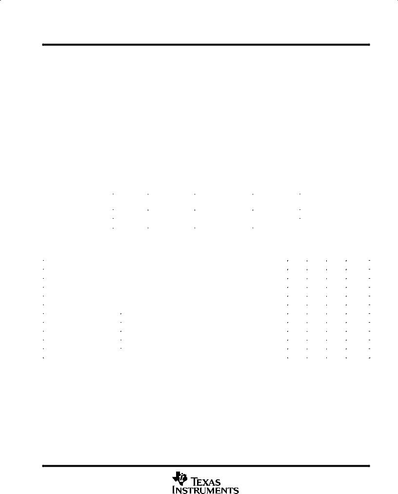
(TOP VIEW) |
|
||
D Designed to Support Data Rates Up to |
VDD |
|
|
|
|
VCC |
|
1 |
16 |
|
|||
120 kbits/s Over 3-m Cable |
|
|
||||
|
|
|
|
|||
D ESD Protection Exceeds 5 kV on All Pins |
1RA |
|
2 |
15 |
|
1RY |
1DY |
|
3 |
14 |
|
1DA |
|
|
|
|||||
D Flow-Through Design |
|
|
||||
2RA |
|
4 |
13 |
|
2RY |
|
|
|
|||||
D Wide-Driver Supply Voltage . . . ±4.5 V |
|
|
||||
2DY |
|
5 |
12 |
|
2DA |
|
|
|
|||||
to ±15 V |
3RA |
|
6 |
11 |
|
3RY |
|
|
|||||
D Functionally Interchangeable With Motorola |
3DY |
|
7 |
10 |
|
3DA |
|
|
|||||
MC145406 and Texas Instruments |
VSS |
|
8 |
9 |
|
GND |
|
|
|||||
|
|
|
|
|
||
SN75C1406 |
|
|
|
|
|
|
|
|
|
|
|
|
|
description
The TL145406 is a bipolar device containing three independent drivers and receivers that are used to interface data terminal equipment (DTE) with data circuit-terminating equipment (DCE). The drivers and receivers of the TL145406 are similar to those of the SN75188 quadruple driver and SN75189A quadruple receiver, respectively. The pinout matches the flow-through design of the SN75C1406 to reduce the board space required and allow easy interconnection. The bipolar circuits and processing of the TL145406 provide a rugged low-cost solution for this function at the expense of quiescent power and external passive components relative to the SN75C1406.
The TL145406 complies with the requirements of the EIA/TIA 232-E and ITU (formerly CCITT) V.28 standards. These standards are for data interchange between a host computer and peripheral at signalling rates up to 20 kbit/s. The switching speeds of the TL145406 are fast enough to support rates up to 120 kbit/s with lower capacitive loads (shorter cables). Interoperability at the higher signalling rates cannot be assured unless the designer has design control of the cable and the interface circuits at both ends. For interoperability at signalling rates to 120 kbit/s, use of EIA/TIA-423-B (ITU V.10) and EIA/TIA-422-B (ITU V.11) standards are recommended.
The TL145406 is characterized for operation from 0°C to 70°C.
logic symbol² |
|
|
|
|
logic diagram (positive logic) |
|
|
|||||||||||
1RA |
2 |
|
15 |
1RY |
Typical of each receiver |
|
|
|||||||||||
|
|
|
|
|||||||||||||||
4 |
|
|
13 |
|
|
|
|
|
|
|
|
|
|
|
|
|
||
2RA |
|
2RY |
2, 4, 6 |
|
|
|
|
|
|
|
|
15, 13, 11 |
RY |
|||||
|
|
|
|
|
|
|
|
|
||||||||||
|
|
|
|
|||||||||||||||
3RA |
6 |
|
|
11 |
3RY |
RA |
|
|
|
|
|
|
|
|
|
|
||
|
|
|
|
|
|
|||||||||||||
|
|
|
|
|
|
|
|
|
|
|
|
|||||||
|
|
|
|
|
|
|
|
|
|
|
|
|
|
|||||
3 |
|
|
14 |
|
|
|
|
|
|
|
|
|
|
|
|
|
||
1DY |
|
1DA |
Typical of each driver |
|
|
|||||||||||||
|
|
|
|
|||||||||||||||
5 |
|
|
12 |
|
|
|||||||||||||
|
|
|
|
|
|
|||||||||||||
2DY |
|
|
2DA |
|
|
|
|
|
|
|
|
|
|
|
|
|
||
7 |
|
|
10 |
3, 5, 7 |
|
|
|
|
|
|
|
|
14, 12, 10 |
|
||||
3DY |
|
3DA |
|
|
|
|
|
|
|
|
DA |
|||||||
|
|
|||||||||||||||||
|
|
|
|
DY |
|
|
|
|
|
|
|
|
|
|||||
|
|
|
|
|
|
|
|
|
|
|
|
|
||||||
²This symbol is in accordance with ANSI/IEEE Std 91-1984 and IEC Publication 617-12.
Please be aware that an important notice concerning availability, standard warranty, and use in critical applications of
Texas Instruments semiconductor products and disclaimers thereto appears at the end of this data sheet.
PRODUCTION DATA information is current as of publication date. Products conform to specifications per the terms of Texas Instruments standard warranty. Production processing does not necessarily include testing of all parameters.
Copyright 1995, Texas Instruments Incorporated
POST OFFICE BOX 655303 •DALLAS, TEXAS 75265 |
1 |

TL145406
TRIPLE RS-232 DRIVERS/RECEIVERS
SLLS185A ± DECEMBER 1994 ± REVISED MARCH 1995
schematic (each driver)
To Other Drivers
VDD ESD
11.6 kΩ |
9.4 kΩ |
Input DAx 
 ESD
ESD
75.8 Ω |
Ω |
|
320 |
DYx Output |
|
|
ESD |
4.2 kΩ
GND
To Other |
|
Drivers |
|
10.4 kΩ |
68.5 Ω |
3.3 kΩ |
VSS  ESD
ESD
To Other Drivers
Resistor values shown are nominal.
schematic (each receiver)
To Other Receivers
ESD VCC
9 kΩ |
5 kΩ |
1.66 kΩ |
ESD  RYx Output
2 kΩ
Input RAx |
3.8 kΩ |
ESD |
10 kΩ
GND
To Other Receivers
Resistor values shown are nominal.
2 |
POST OFFICE BOX 655303 •DALLAS, TEXAS 75265 |
TL145406
TRIPLE RS-232 DRIVERS/RECEIVERS
SLLS185A ± DECEMBER 1994 ± REVISED MARCH 1995
absolute maximum ratings over operating free-air temperature range (unless otherwise noted)²
Supply voltage, VCC (see Note 1) . . . . . . . . . . . . . . . . . . . . . . . . . . . . . . . . . . . . . . . |
. . . . . . . . . . . . . . . . . . . . . 10 V |
|
Supply voltage, VDD (see Note 1) . . . . . . . . . . . . . . . . . . . . . . . . . . . . . . . . . . . . . . . |
. . . . . . . . . . . . . . . . . . . . . 15 V |
|
Supply voltage, VSS (see Note 1) . . . . . . . . . . . . . . . . . . . . . . . . . . . . . . . . . . . . . . . |
. . . . . . . . . . . . . . . . . . . . ±15 V |
|
Input voltage range: Driver . . . . . . . . . . . . . . . . . . . . . . . . . . . . . . . . . . . . . . . . . . . |
. . . . . . . . . . . . . . ±15 V to 7 |
V |
Receiver . . . . . . . . . . . . . . . . . . . . . . . . . . . . . . . . . . . . . . . . |
. . . . . . . . . . . . ±30 V to 30 |
V |
Driver output voltage range . . . . . . . . . . . . . . . . . . . . . . . . . . . . . . . . . . . . . . . . . . . . |
. . . . . . . . . . . . . ±15 V to 15 |
V |
Receiver low-level output current . . . . . . . . . . . . . . . . . . . . . . . . . . . . . . . . . . . . . . . |
. . . . . . . . . . . . . . . . . . . 20 mA |
|
Continuous total power dissipation . . . . . . . . . . . . . . . . . . . . . . . . . . . . . . . . . . . . . |
See Dissipation Rating Table |
|
Operating free-air temperature range, TA . . . . . . . . . . . . . . . . . . . . . . . . . . . . . . . . |
. . . . . . . . . . . . . . 0°C to 70°C |
|
Storage temperature range, Tstg . . . . . . . . . . . . . . . . . . . . . . . . . . . . . . . . . . . . . . . . |
. . . . . . . . . . ±65°C to 150°C |
|
Lead temperature 1,6 mm (1/16 inch) from case for 10 seconds . . . . . . . . . . . . |
. . . . . . . . . . . . . . . . . . . 260°C |
|
²Stresses beyond those listed under ªabsolute maximum ratingsº may cause permanent damage to the device. These are stress ratings only, and functional operation of the device at these or any other conditions beyond those indicated under ªrecommended operating conditionsº is not implied. Exposure to absolute-maximum-rated conditions for extended periods may affect device reliability.
NOTE 1: All voltages are with respect to the network ground terminal.
DISSIPATION RATING TABLE³
PACKAGE |
TA ≤ 25°C |
DERATING FACTOR |
TA ≤ 70°C |
|
POWER RATING |
ABOVE TA = 25°C |
POWER RATING |
||
|
||||
DW |
1256 mW |
9.7 mW/°C |
819 mW |
|
N |
1943 mW |
14.9 mW/°C |
1272 mW |
|
|
|
|
|
³Dissipation ratings are the inverse of the traditional junction-to-case thermal resistance (RθJA).
recommended operating conditions
|
|
MIN |
NOM |
MAX |
UNIT |
|
|
|
|
|
|
Supply voltage, VDD |
|
7.5 |
9 |
15 |
V |
Supply voltage, VSS |
|
± 7.5 |
± 9 |
± 15 |
V |
Supply voltage, VCC |
|
4.5 |
5 |
5.5 |
V |
High-level input voltage, VIH (driver only) |
1.9 |
|
|
V |
|
Low-level input voltage, VIL (driver only) |
|
|
0.8 |
V |
|
High-level output current, IOH |
Driver |
|
|
± 6 |
mA |
|
|
|
|
||
Receiver |
|
|
± 0.5 |
||
|
|
|
|
||
|
|
|
|
|
|
Low-level output current, IOL |
Driver |
|
|
6 |
mA |
|
|
|
|
||
Receiver |
|
|
16 |
||
|
|
|
|
||
|
|
|
|
|
|
Operating free-air temperature, TA |
0 |
|
70 |
°C |
|
POST OFFICE BOX 655303 •DALLAS, TEXAS 75265 |
3 |
 Loading...