


|
|
|
|
|
|
|
|
|
|
|
|
|
|
TL070 |
|
|
|
|
|
|
|
|
|
|
|
|
|
|
JFET-INPUT |
||
|
|
|
|
|
OPERATIONAL AMPLIFIER |
||||||||||
|
|
|
|
SLOS121A ± NOVEMBER 1993 ± REVISED AUGUST 1994 |
|||||||||||
|
|
|
|
|
|
|
|
|
|
|
|
|
|
|
|
D |
Low Power Consumption |
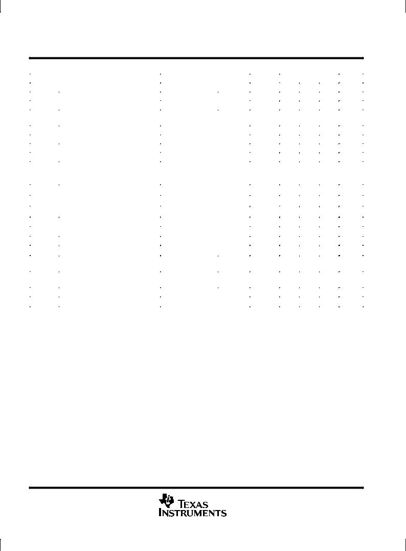
D, P, OR PW PACKAGE |
|||||||||||||
D Wide Common-Mode and Differential |
|
|
|
(TOP VIEW) |
|
|
|
|
|||||||
|
|
|
|
|
|
|
|
|
|
|
|
||||
|
Voltage Ranges |
N1/COMP |
|
1 |
8 |
|
|
COMP |
|||||||
|
|
|
|
||||||||||||
D Low Input Bias and Offset Currents |
|
|
|
||||||||||||
IN ± |
|
2 |
7 |
|
|
VCC + |
|||||||||
|
|
|
|||||||||||||
|
Output Short-Circuit Protection |
IN + |
|
|
|
|
|
|
|
||||||
D |
|
3 |
6 |
|
|
OUT |
|||||||||
D |
Low Total Harmonic Distortion |
VCC ± |
|
4 |
5 |
|
|
OFFSET N2 |
|||||||
|
|
||||||||||||||
|
|
|
|
|
|
|
|
|
|
||||||
|
0.003% Typ |
|
|
|
|
|
|
|
|
|
|
|
|
||
|
|
|
|
|
|
|
|
|
|
|
|
|
|||
D |
Low Noise |
|
|
symbol |
|
|
|
|
|
|
|
|
|
||
|
Vn = 18 nV/√ Hz Typ at f = 1 kHz |
|
|
|
|
|
|
|
|
|
|||||
|
|
|
|
|
|
|
|
|
|
|
|
|
|||
D |
High Input Impedance . . . JFET Input Stage |
N1/COMP |
|
|
|
|
|
|
|
|
|
|
|||
|
|
|
|
|
|
|
|
|
|
||||||
D Common-Mode Input Voltage Range |
COMP |
|
|
|
|
|
|
|
|
|
|
|
|||
|
Includes VCC+ |
|
|
|
|
|
|
|
|
|
|
||||
|
|
|
|
|
|
|
|
|
|
|
|||||
|
|
|
|
|
|
|
|
|
|
|
|
|
|||
D Latch-Up-Free Operation |
IN + |
|
|
|
+ |
|
|
|
|
|
|
|
|||
|
|
|
|
|
|
|
|
|
|
||||||
D High Slew Rate . . . 13 V/μs Typ |
|
|
|
|
|
|
|
OUT |
|||||||
IN ± |
|
|
|
± |
|
|
|
|
|
||||||
|
|
|
|
|
|
|
|
|
|
|
|
||||
|
|
|
|
|
|
|
|
|
|
|
|
|
|||
|
|
|
|
|
|
|
|
|
|
|
|
|
|||
description
The JFET-input TL070 operational amplifier is designed as the lower-noise version of the TL080
amplifier with low input bias and offset currents and fast slew rate. The low harmonic distortion and low noise make the TL070 ideally suited for high-fidelity and audio preamplifier applications. This amplifier features JFET inputs (for high input impedance) coupled with bipolar output stages integrated on a single monolithic chip.
The TL070C device is characterized for operation from 0°C to 70°C. The TL070I device is characterized for operation from ± 40°C to 85°C. The TL070M device is characterized for operation from ±55°C to 125°C.
AVAILABLE OPTIONS
|
VIOmax |
|
PACKAGE |
|
|
TA |
|
|
|
||
SMALL OUTLINE |
PLASTIC DIP |
TSSOP |
|||
AT 25°C |
|||||
|
(D) |
(P) |
(PW) |
||
|
|
||||
|
|
|
|
|
|
0°C to 70°C |
10 mV |
TL070CD |
TL070CP |
TL070CPW |
|
|
|
|
|
|
|
± 40°C to 85°C |
10 mV |
TL070ID |
TL070IP |
Ð |
|
|
|
|
|
|
|
± 55°C to 125°C |
10 mV |
TL070MD |
TL070MP |
Ð |
|
|
|
|
|
|
PRODUCTION DATA information is current as of publication date. Products conform to specifications per the terms of Texas Instruments standard warranty. Production processing does not necessarily include testing of all parameters.
Copyright 1994, Texas Instruments Incorporated
POST OFFICE BOX 655303 •DALLAS, TEXAS 75265 |
1 |

TL070
JFET-INPUT
OPERATIONAL AMPLIFIER
SLOS121A ± NOVEMBER 1993 ± REVISED AUGUST 1994
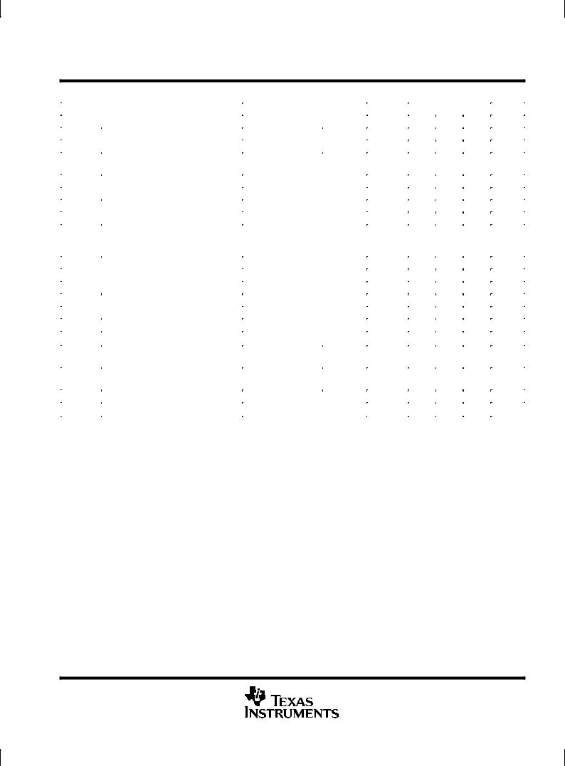
schematic
VCC +
IN + |
|
|
IN ± |
64 Ω |
Ω |
|
128 |
OUT
64 Ω
N1/COMP
OFFSET N2
COMP
1080 Ω |
1080 |
Ω |
|
VCC ±
All component values shown are nominal.
COMPONENT COUNT ²
Transistors |
13 |
Diodes |
2 |
Resistors |
10 |
epi-FET |
1 |
JFET |
2 |
² Includes all bias and trim circuitry
2 |
POST OFFICE BOX 655303 •DALLAS, TEXAS 75265 |

TL070
JFET-INPUT
OPERATIONAL AMPLIFIER
SLOS121A ± NOVEMBER 1993 ± REVISED AUGUST 1994
absolute maximum ratings over operating free-air temperature range (unless otherwise noted)²
Supply voltage, VCC + (see Note 1) . . . . . . . . . . . . . . . . . . . . . . . . . . . . . . . . . . . . . |
. . . . . . . . . . . . . . . . . . . . 18 |
V |
Supply voltage, VCC ± . . . . . . . . . . . . . . . . . . . . . . . . . . . . . . . . . . . . . . . . . . . . . . . . . |
. . . . . . . . . . . . . . . . . . . ±18 V |
|
Differential input voltage, VID (see Note 2) . . . . . . . . . . . . . . . . . . . . . . . . . . . . . . . |
. . . . . . . . . . . . . . . . . . . ± 30 |
V |
Input voltage, VI (see Notes 1 and 3) . . . . . . . . . . . . . . . . . . . . . . . . . . . . . . . . . . . |
. . . . . . . . . . . . . . . . . . . ± 15 |
V |
Duration of short-circuit current (see Note 4) . . . . . . . . . . . . . . . . . . . . . . . . . . . . . |
. . . . . . . . . . . . . . . . unlimited |
|
Continuous total dissipation . . . . . . . . . . . . . . . . . . . . . . . . . . . . . . . . . . . . . . . . . . . |
See Dissipation Rating Table |
|
Operating free-air temperature range, TA: C suffix . . . . . . . . . . . . . . . . . . . . . . . |
. . . . . . . . . . . . . . 0°C to 70°C |
|
I suffix . . . . . . . . . . . . . . . . . . . . . . . |
. . . . . . . . . . . ±40°C to 85°C |
|
M suffix . . . . . . . . . . . . . . . . . . . . . . . |
. . . . . . . . . . ±55°C to 125°C |
|
Storage temperature range . . . . . . . . . . . . . . . . . . . . . . . . . . . . . . . . . . . . . . . . . . . . |
. . . . . . . . . . ±65°C to 150°C |
|
Lead temperature 1,6 mm (1/16 inch) from case for 10 seconds . . . . . . . . . . . . |
. . . . . . . . . . . . . . . . . . . 260°C |
|
²Stresses beyond those listed under ªabsolute maximum ratingsº may cause permanent damage to the device. These are stress ratings only, and functional operation of the device at these or any other conditions beyond those indicated under ªrecommended operating conditionsº is not
implied. Exposure to absolute-maximum-rated conditions for extended periods may affect device reliability.
NOTES: 1. All voltage values, except differential voltages, are with respect to the midpoint between VCC + and VCC ±.
2.Differential voltages are at IN+ with respect to IN ±.
3.The magnitude of the input voltage must never exceed the magnitude of the supply voltage or 15 V, whichever is less.
4.The output may be shorted to ground or to either supply. Temperature and/or supply voltages must be limited to ensure that the dissipation rating is not exceeded.
DISSIPATION RATING TABLE
PACKAGE |
TA ≤ 25°C |
DERATING |
DERATE |
TA = 70°C |
TA = 85°C |
TA = 125°C |
|
POWER RATING |
FACTOR |
ABOVE TA |
POWER RATING |
POWER RATING |
POWER RATING |
||
|
|||||||
D |
680 mW |
5.8 mW/°C |
33°C |
464 mW |
377 mW |
145 mW |
|
P |
680 mW |
8.0 mW/°C |
65°C |
640 mW |
520 mW |
200 mW |
|
PW |
525 mW |
4.2 mW/°C |
70°C |
336 mW |
N/A |
N/A |
|
|
|
|
|
|
|
|
POST OFFICE BOX 655303 •DALLAS, TEXAS 75265 |
3 |
TL070
JFET-INPUT
OPERATIONAL AMPLIFIER
SLOS121A ± NOVEMBER 1993 ± REVISED AUGUST 1994
electrical characteristics, VCC ± = ± 15 V (unless otherwise noted)
|
PARAMETER |
TEST CONDITIONS |
|
T ² |
|
TL070C |
|
UNIT |
|
|
|
|
|
|
|||||
|
|
|
|
|
|||||
|
|
|
|
|
A |
MIN |
TYP |
MAX |
|
|
|
|
|
|
|
|
|||
VIO |
Input offset voltage |
VO = 0, |
RS |
= 50 Ω |
25°C |
|
3 |
10 |
mV |
|
|
|
|
||||||
Full range |
|
|
13 |
||||||
|
|
|
|
|
|
|
|
||
|
|
|
|
|
|
|
|
|
|
αVIO |
Temperature coefficient of input offset |
VO = 0, |
RS = 50 Ω |
Full range |
|
18 |
|
μV/°C |
|
voltage |
|
|
|||||||
|
|
|
|
|
|
|
|
|
|
|
|
|
|
|
|
|
|
|
|
IIO |
Input offset current |
VO = 0 |
|
|
25°C |
|
5 |
100 |
pA |
|
|
|
|
|
|
|
|||
|
|
Full range |
|
|
10 |
nA |
|||
|
|
|
|
|
|
|
|||
|
|
|
|
|
|
|
|
|
|
I |
Input bias current³ |
V = 0 |
|
|
25°C |
|
65 |
200 |
pA |
|
|
|
|
|
|
|
|||
|
|
|
|
|
|
|
|||
IB |
|
O |
|
|
Full range |
|
|
7 |
nA |
|
|
|
|
|
|
|
|||
|
|
|
|
|
|
|
±12 |
|
|
VICR |
Common-mode input voltage range |
|
|
|
25°C |
±11 |
to |
|
V |
|
|
|
|
|
|
|
15 |
|
|
|
|
|
|
|
|
|
|
|
|
|
|
RL = 10 kΩ |
|
|
25°C |
±12 |
±13.5 |
|
|
VOM |
Maimum peak output voltage swing |
RL ≥ 10 kΩ |
|
|
Full range |
±12 |
|
|
V |
|
|
RL ≥ 2 kΩ |
|
|
±10 |
|
|
|
|
|
|
|
|
|
|
|
|
||
AVD |
Large-signal differential voltage |
VO = ±10 V, |
|
|
25°C |
25 |
200 |
|
V/mV |
amplification |
RL ≥ 2 kΩ |
|
|
Full range |
15 |
|
|
||
|
|
|
|
|
|
||||
B1 |
Unity-gain bandwidth |
|
|
|
25°C |
|
3 |
|
MHz |
ri |
Input resistance |
|
|
|
25°C |
|
1012 |
|
Ω |
CMRR |
Common-mode rejection ratio |
VIC = VICRmin, |
VO |
= 0, |
25°C |
70 |
100 |
|
dB |
RS = 50 Ω |
|
|
|
||||||
|
|
|
|
|
|
|
|
|
|
kSVR |
Supply voltage rejection ratio |
VCC = ± 9 V to ± 15 V, |
VO |
= 0, |
25°C |
70 |
100 |
|
dB |
( VCC ± / VIO) |
RS = 50 Ω |
|
|
|
|||||
|
|
|
|
|
|
|
|
||
ICC |
Supply current |
VO = 0, |
No load |
25°C |
|
1.4 |
2.5 |
mA |
|
VO1/ VO2 |
Crosstalk attenuation |
AVD = 100 |
|
|
25°C |
|
120 |
|
dB |
²All characteristics are measured under open-loop conditions with zero common-mode voltage unless otherwise specified. Full range for TA is °C to 70°C.
³Input bias currents of a FET-input operational amplifier are normal junction reverse currents, which are temperature sensitive as shown in Figure 5. Pulse techniques must be used that will maintain the junction temperature as close to the ambient temperature as possible.
4 |
POST OFFICE BOX 655303 •DALLAS, TEXAS 75265 |
TL070
JFET-INPUT
OPERATIONAL AMPLIFIER
SLOS121A ± NOVEMBER 1993 ± REVISED AUGUST 1994
electrical characteristics, VCC ± = ± 15 V (unless otherwise noted)
|
PARAMETER |
TEST CONDITIONS |
|
T ² |
|
TL070I |
|
UNIT |
|
|
|
|
|
|
|||||
|
|
|
|
|
|||||
|
|
|
|
|
A |
MIN |
TYP |
MAX |
|
|
|
|
|
|
|
|
|||
VIO |
Input offset voltage |
VO = 0, |
RS |
= 50 Ω |
25°C |
|
3 |
10 |
mV |
|
|
|
|
||||||
Full range |
|
|
13 |
||||||
|
|
|
|
|
|
|
|
||
|
|
|
|
|
|
|
|
|
|
αVIO |
Temperature coefficient of input offset |
VO = 0, |
RS = 50 Ω |
Full range |
|
18 |
|
μV/°C |
|
voltage |
|
|
|||||||
|
|
|
|
|
|
|
|
|
|
|
|
|
|
|
|
|
|
|
|
IIO |
Input offset current |
VO = 0 |
|
|
25°C |
|
5 |
100 |
pA |
|
|
|
|
|
|
|
|||
|
|
Full range |
|
|
10 |
nA |
|||
|
|
|
|
|
|
|
|||
|
|
|
|
|
|
|
|
|
|
I |
Input bias current³ |
V = 0 |
|
|
25°C |
|
65 |
200 |
pA |
|
|
|
|
|
|
|
|||
|
|
|
|
|
|
|
|||
IB |
|
O |
|
|
Full range |
|
|
20 |
nA |
|
|
|
|
|
|
|
|||
|
|
|
|
|
|
|
±12 |
|
|
VICR |
Common-mode input voltage range |
|
|
|
25°C |
±11 |
to |
|
V |
|
|
|
|
|
|
|
15 |
|
|
|
|
|
|
|
|
|
|
|
|
|
|
RL = 10 kΩ |
|
|
25°C |
±12 |
±13.5 |
|
|
VOM |
Maximum peak output voltage swing |
RL ≥ 10 kΩ |
|
|
Full range |
±12 |
|
|
V |
|
|
RL ≥ 2 kΩ |
|
|
±10 |
|
|
|
|
|
|
|
|
|
|
|
|
||
AVD |
Large-signal differential voltage |
VO = ±10 V, |
|
|
25°C |
25 |
200 |
|
V/mV |
amplification |
RL ≥ 2 kΩ |
|
|
Full range |
15 |
|
|
||
|
|
|
|
|
|
||||
B1 |
Unity-gain bandwidth |
|
|
|
25°C |
|
3 |
|
MHz |
ri |
Input resistance |
|
|
|
25°C |
|
1012 |
|
Ω |
CMRR |
Common-mode rejection ratio |
VIC = VICRmin, |
VO |
= 0, |
25°C |
70 |
100 |
|
dB |
RS = 50 Ω |
|
|
|
||||||
|
|
|
|
|
|
|
|
|
|
kSVR |
Supply voltage rejection ratio |
VCC = ± 9 V to ± 15 V, |
VO |
= 0 |
25°C |
70 |
100 |
|
dB |
( VCC ± / VIO) |
RS = 50 Ω |
|
|
|
|||||
|
|
|
|
|
|
|
|
||
ICC |
Supply current |
VO = 0, |
No load |
25°C |
|
1.4 |
2.5 |
mA |
|
VO1/ VO2 |
Crosstalk attenuation |
AVD = 100 |
|
|
25°C |
|
120 |
|
dB |
²All characteristics are measured under open-loop conditions with zero common-mode voltage unless otherwise specified. Full range for TA is
± 40°C to 85°C.
³Input bias currents of a FET-input operational amplifier are normal junction reverse currents, which are temperature sensitive as shown in Figure 5. Pulse techniques must be used that will maintain the junction temperature as close to the ambient temperature as possible.
POST OFFICE BOX 655303 •DALLAS, TEXAS 75265 |
5 |
 Loading...