


Installation Guide
Two-Outlet Thermostatic Valve
K-528
M product numbers are for Mexico (i.e. K-12345M)
Los números de productos seguidos de M corresponden a México (Ej. K-12345M)
Français, page ″Français-1″ Español, página ″Español-1″
1145587-2-A

IMPORTANT INSTRUCTIONS
WARNING: When using electrical products, basic precautions should always be followed, including the following:
DANGER: Risk of electric shock. Grounding is required. Connect only to circuits protected by a Ground-Fault Circuit-Interrupter (GFCI) or Residual Current Device (RCD). The unit should be installed and grounded by a qualified service representative.
WARNING: Risk of electric shock. A licensed electrician should route all electrical wiring.
WARNING: Risk of electric shock. Disconnect power to the valve before servicing.
WARNING: Unauthorized modification may cause poor performance of the valve. Do not make modifications to the valve as this could adversely affect the performance of the valve and void the warranty. Kohler Co. shall not be liable under its warranty or otherwise for personal injury or damage caused by any such unauthorized modification.
WARNING: Risk of injury or property damage. Please read all instructions thoroughly before beginning installation.
NOTICE: Follow all plumbing, electrical, and building codes.
NOTICE: Provide generous, unrestricted service access to the valve. Provide access for servicing the valve and interface. This access must be located immediately next to the valve. Refer to the roughing-in information.
1145587-2-A |
2 |
Kohler Co. |
Specifications
Pressures
Maximum Static Pressure |
125 psi, 862 kPa, 8.6 bar |
Supply Pressure Differential* |
Max 5 psi, 34.5 kPa, 0.34 bar (Equal pressures recommended.) |
Minimum Flow Rate |
1.6 gpm (Less than 72 psi dynamic pressure.) |
|
6 lpm (Less than 500 kPa maintaining pressure.) |
|
2.1 gpm (Greater than 72 psi dynamic pressure.) |
|
8 lpm (Greater than 500 kPa maintaining pressure.) |
Temperatures |
|
Programmable Temperature |
Max 120°F (49°C) Min 86°F (30°C) Full cold may also be selected. |
Default Temperature at Start-up |
100°F (38°C) |
Minimum Mixed Temperature |
3.6°F (2°C) |
Differential from Hot Supply |
|
Temperature Stability at Recommended |
+/- 1.6°F (1°C) |
Supply Conditions |
|
Ambient Temperature |
Greater than 34°F (1°C), Max 104°F (40°C) |
Maximum Relative Humidity |
95% non-condensing |
Electrical |
|
Electrical Service |
120 V, 15 A, 60 Hz |
User Interface Cable Length (supplied) |
20 ft (6.1 m) |
|
|
* In commercial applications where there is a large difference in hot and cold supply pressures or frequent fluctuation in either supply line is anticipated, it is strongly recommended that pressure regulators be installed.
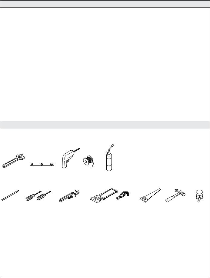
Tools and Materials
|
|
|
|
|
Plus: |
|
|
|
|
|
|
• (2) |
1/2" Union Connectors |
|
|
|
|
|
• Wood and Framing Materials |
|
|
|
|
|
|
• PEX Tubing, Copper Tubing, or PVC |
|
Adjustable |
Level |
Drill |
Solder |
Propane |
• (2) |
Water Hammer Arrestors (Recommended) |
• (2) |
Supply Shut-Off Valves |
|||||
Wrench |
|
|
|
Torch |
|
|
Pencil |
Screwdrivers |
Pipe Wrench |
Hacksaw or Tube Cutter Wood Saw |
Hammer |
Sealant |
|
|
|
|
|
Tape |
Kohler Co. |
3 |
1145587-2-A |
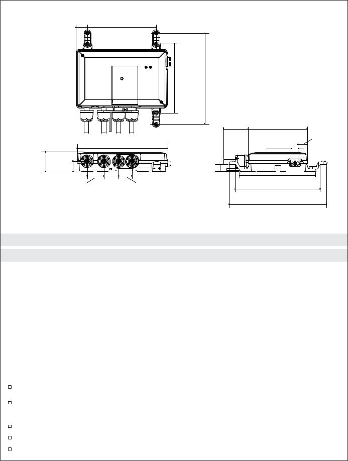
1-9/16"
(4 cm) 9-7/16" (24 cm)
9-1/2" 12-1/2"
(24.1 cm) (31.8 cm)
|
|
|
|
3-3/8" |
8-1/16" |
|
|
|
|
|
(8.6 cm) |
(20.5 cm) |
1-5/16" |
|
|
|
|
|
|
|
|
|
12-1/2" |
|
|
13/16" |
(3.3 cm) |
|
|
|
|
|
||
|
|
(31.8 cm) |
|
(2.1 cm) |
|
|
2-11/16" |
1-7/16" |
|
|
1" |
|
|
(6.8 cm) |
(3.7 cm) |
|
|
(2.5 cm) |
|
|
|
|
2" |
|
|
10-3/16" |
|
|
2-3/8" |
1-13/16" |
|
(25.9 cm) |
|
|
|
(5.1 cm) |
|
|
|||
|
(6 cm) |
(4.6 cm) |
|
11-5/8" |
|
|
|
|
|
|
|
(29.5 cm) |
|
|
|
|
|
|
13-3/8" |
|
|
|
|
|
|
(34 cm) |
|
Roughing-In
Before You Begin
NOTICE: Do not install the valve under a whirlpool surround or any location where the temperature may reach temperatures over 104°F (40°C). The valve and its integrated power supply is rated to operate in temperatures up to 104°F (40°C).
NOTICE: Do not apply excessive heat near the valve or apply flux or acids directly onto the valve. This valve contains plastic and rubber components which will melt if heat is directly applied.
NOTICE: Do not apply petroleum-based lubricants to the valve components. Doing so will damage the valve components.
NOTICE: Do not use oil-based, non-setting compounds, such as plumbers putty, on the threaded connections.
NOTICE: If the digital valve will be used for a bath/shower application, the bath fill supply line must be routed from the #1 outlet port.
Observe all local plumbing, building, and electrical codes.
Read these instructions and determine all required components along with their installation locations before beginning this installation.
Provide access for servicing.
For optimum performance, 1/2″ dedicated water supply lines are recommended.
When possible, install the valve prior to installing the interface(s).
1145587-2-A |
4 |
Kohler Co. |

Before You Begin (cont.)
If possible, flush all piping thoroughly before installing the valve to prevent clogging the inlet filters. If the valve is installed when the pipes are flushed, clean the inlet screens before using the system.
This valve is not intended for single-outlet use.
A qualified electrician should install a 120 V GFCI electrical outlet, within the stud framing, in close proximity to the digital mixing valve.
If possible, install the electrical outlet prior to installing the valve.
This valve complies with UL1951, ASME A112.18.1, ASSE 1016, CSA B125, and CSA C222 No. 218.2-93. This valve is listed with ASSE, IAPMO/cUPC, and UL.
Kohler Co. reserves the right to make revisions in the design of faucets without notice, as specified in the Price Book.
Kohler Co. |
5 |
1145587-2-A |
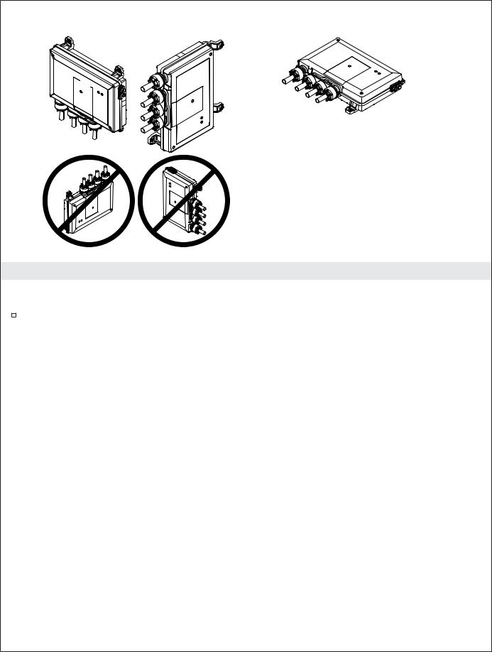
Mounting on a Vertical Surface |
Mounting on a Horizontal Surface |
1. Valve Mounting Configurations
NOTICE: Do not mount the valve with the inlets located at the top. Doing so will damage this product.
Vertical and horizontal mounting options are shown above. Do not mount the valve with the inlets or cable sockets pointing up.
1145587-2-A |
6 |
Kohler Co. |
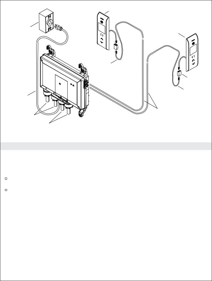
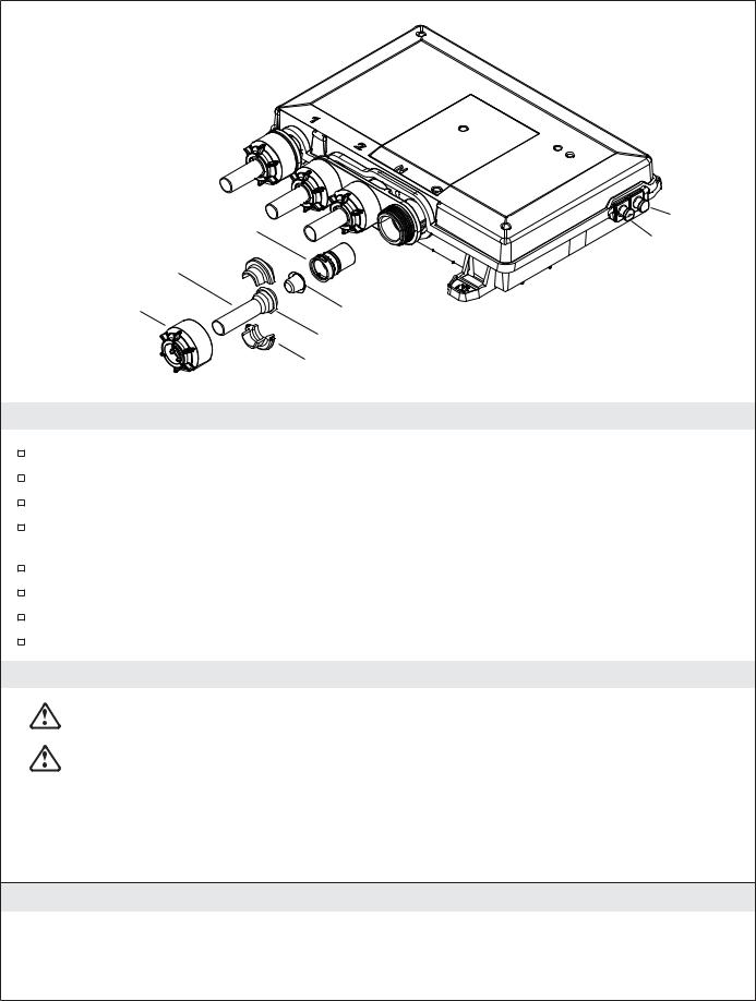
Outlet
Power Cord
Outlets
Supply Inlets
Interface
Interface
Drip
Loop
Coupler
Drip Loop
20' (6.1 m) Cables
NOTE: Only one interface, installed inside the shower, is required. An additional interface can be installed outside the shower.
2. Preparation
NOTICE: If the digital valve will be used for a bath/shower application, the bath fill supply line must be routed from the #1 outlet port.
NOTE: The two valve interfaces are identical. Either can be used for primary and secondary connections. One is located outside the showering enclosure, while the other is located inside the showering enclosure.
Determine all required components along with their installation locations before beginning this installation.
When routing piping, keep in mind the numbers marked at each valve outlet must correspond to the appropriate showering component for the preprogrammed or custom showering experiences to function properly.
Kohler Co. |
7 |
1145587-2-A |

Board Mount |
Cross Brace Mount |
2-3/4"
(7 cm) 14-1/2" (36.8 cm) Min 14-1/2" (36.8 cm) Min Min
11-5/8"
(29.5 cm)
9-1/2"
(24.1 cm) 12-1/2"
(31.8 cm)
16" (40.6 cm) Centers
Notch bottom brace.
3. Prepare the Site
NOTE: Vertical wall installation shown. The valve can also be mounted to a horizontal surface. Refer to the ″Valve Mounting Configurations″ section.
This product is designed to fit within a minimum 14-1/2″ (36.8 cm) 2x4 stud cavity. If necessary to modify the stud cavity, apply adequate bracing for mounting the valve.
1145587-2-A |
8 |
Kohler Co. |
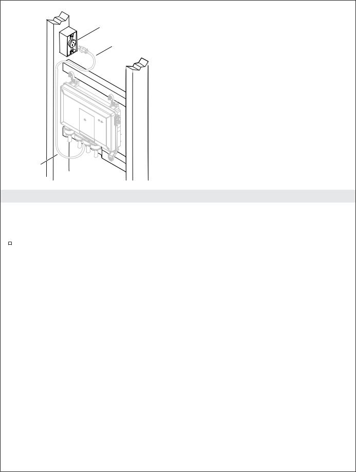
Place outlet higher than valve.
Power Cord
Drip Loop
4. Install the Electrical Outlet
NOTICE: Do not install the valve under a whirlpool surround or in any location where the temperature may reach temperatures over 104°F (40°C). The valve and its integrated power supply are rated to operate in temperatures up to 104°F (40°C).
Install a 120 V GFCI electrical outlet, within the stud framing, in close proximity to the valve. Locate the outlet above the valve allowing ample space to mount the valve in close proximity to the
outlet.
Kohler Co. |
9 |
1145587-2-A |
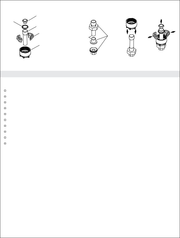
Screen (Inlets Only)
O-Ring
Inlet/Outlet Tube
Adapter Lock
1/2" Union
Solder this connection.
Adapter Nut
5. Assemble the Adapters and Unions
NOTICE: Do not apply excessive heat near the valve or apply flux or acids directly onto the valve. This valve contains plastic and rubber components which will melt if heat is directly applied.
Disassemble the adapter. Ensure all rubber and plastic components are removed.
Slide the union nut onto the inlet/outlet tube.
Solder the inlet/outlet tube to the union. Allow to cool completely.
Assemble the union.
Slide the adapter nut onto the inlet/outlet tube.
Assemble the adapter lock onto the inlet/outet tube and slide the assembly into the adapter nut.
Slide the O-ring onto the inlet/outlet tube.
For inlet tubes only: Insert the screen into the end of the inlet tube.
Reinstall the adapter assembly to the valve.
Repeat for all inlet/outlet tubes as required.
1145587-2-A |
10 |
Kohler Co. |

Offset Foot
Cross Brace Mount
Board Mount
1/2" Union
Water Hammer Arrestor
Shut-Off Valve
6. Install the Valve
NOTICE: Do not apply excessive heat near the valve or apply flux or acids directly onto the valve. This valve contains plastic and rubber components which will melt if heat is directly applied.
NOTICE: Do not use oil-based, non-setting compounds, such as plumbers putty, on the threaded connections.
IMPORTANT! If your water supply has high amounts of particulates, install wye strainers in the supply lines.
Route the 1/2″ dedicated water supply lines. To allow access to the inlet screens for periodic cleaning, install a removable segment of piping to the valve inlets using unions.
Install supply shut-off valves and water hammer arrestors in the supply lines prior to the valve.
Hold the valve up to the installation location and verify fit.
Mark the hole locations.
Predrill the holes.
Secure the valve with the washers and screws. Do not overtighten.
IMPORTANT! Make sure the components are connected to the corresponding numbered outlet(s) on the valve.
Route the piping from the valve outlets to the appropriate shower components based on your chosen configuration.
Connect the supply lines to the valve inlets. Verify that the hot and cold supplies are connected to the appropriate inlets. Hot is red and marked by an ″H,″ cold is blue and marked by a ″C.″
Secure all piping to the framing.
Kohler Co. |
11 |
1145587-2-A |
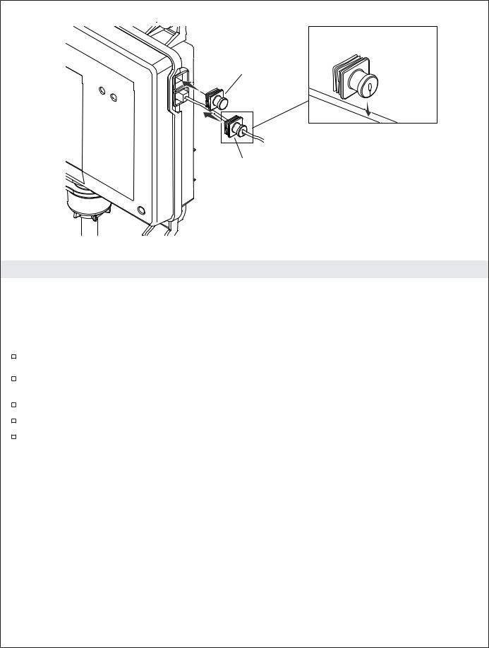
Slide the split boot onto the interface cable.
Solid Boot
Split Boot
7. Complete the Installation
If an interface is not available, proceed to the ″Installation Checkout″ section, and ″Checking the Valve Installation without an Installed Interface.″
NOTICE: Do not plug in the power cord until all interface cables are connected.
NOTE: Make drip loops in all cables and cords.
Route the interface cable(s) in the wall from the valve location to the interface installation locations.
If not already installed, install the interface(s) at this time according to the instructions packed with the product.
Connect the interface cable(s) to the valve.
Verify there is power to the 120 V GFCI electrical outlet.
Plug the power cord into the outlet.
1145587-2-A |
12 |
Kohler Co. |
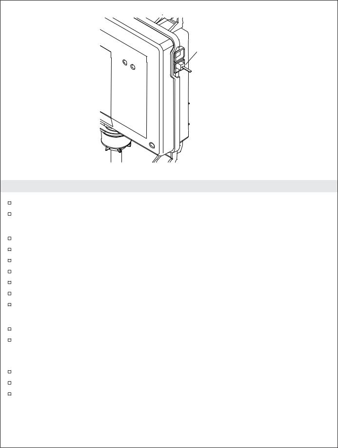
Jumper
8. Installation Checkout
Turn on the water supply to the valve.
Check all connections for leaks and make any adjustments as needed.
Checking the Valve Installation without an Installed Interface
Disconnect the power from the valve.
Insert the jumper into one of the valve sockets.
Reconnect the power to the valve.
Wait 10 seconds for the valve to initialize; outlets will activate.
Check all connections for leaks.
Disconnect the power, then remove the jumper.
Reconnect the power to the valve for normal usage.
Test for Proper Operation (Requires an Installed Interface)
Press the power icon on the user interface. The interface should turn on and the screen will be lit. If not already completed, refer to the ″Digital Interface User Guide″ to set up the interface.
NOTE: For more information about using the user interface and its menus, refer to the user interface Homeowners Guide.
Using the interface, turn on both water outlets.
Check for leaks and make any adjustments as needed.
Verify that the water flow is sufficient for your showering needs.
Exercising the Mixing Valve (Requires an Installed Interface)
NOTE: The maximum water temperature to the outlets is limited to 120°F (49°C). The valve will automatically shut down if the temperature exceeds 120°F (49°C).
Kohler Co. |
13 |
1145587-2-A |

Installation Checkout (cont.)
NOTE: Mixing valves which have been in storage, installed recently, or not been used for some time, should be exercised before running any tests or setting the maximum temperature. Follow the steps below to exercise your valve.
Verify that both hot and cold water are connected to appropriate valve inlets.
Using the up and down arrow icons on the user interface, adjust the temperature from cold to hot and back to cold several times, pausing for 30 seconds at each extreme.
1145587-2-A |
14 |
Kohler Co. |
Check Valve |
Boot |
|
|
|
Split Boot |
Copper Tube
Nut
Screen
O-Ring
Seal
Clean the Inlet Screens
Disconnect the power and turn off the water supply.
Unthread the plastic nuts from the hot and cold inlets.
Remove the copper tubes. The O-ring and screen may be attached to the end of the tube.
If the screen remains in the check valve, use a small flat-blade screwdriver to gently pull the check valve from the valve inlets.
Remove the screens from the copper tubes or check valves.
Clean the screens to remove any dirt or debris.
Rinse or replace the check valves and screens.
Reassemble the inlet connections.
9. Troubleshooting
CAUTION: Risk of personal injury. The valve may contain hot water; be careful when draining any residual water.
WARNING: Risk of electric shock. Disconnect power before performing any maintenance. When disconnected, the product will no longer be electrically live, which will eliminate the risk of electric shock.
It is recommended that any valve maintenance should be performed by a KOHLER Authorized Service Representative.
This troubleshooting guide is for general aid only. For service and installation issues or concerns, call 1-800-4KOHLER.
Troubleshooting Table
Symptoms |
Probable Cause |
Recommended Action |
1. Control panel is not lit. |
A. Valve is not plugged into the |
A. Plug the valve into an outlet. |
|
outlet. |
|
|
|
|
Kohler Co. |
15 |
1145587-2-A |

Troubleshooting (cont.)
Troubleshooting Table
Symptoms |
Probable Cause |
Recommended Action |
|||
|
|
B. |
Interface cable connections may |
B. |
Check all interface cable |
|
|
|
be loose or disconnected. |
|
connections, connect if needed. |
|
|
C. |
Circuit breaker has been |
C. |
Reset the circuit breaker. |
|
|
|
tripped. |
|
|
|
|
D. The valve memory may require |
D. Disconnect and reconnect the valve |
||
|
|
|
resetting. |
|
power cord from the electrical |
|
|
|
A ″straight-through″ cable or |
|
outlet. |
|
|
E. |
E. |
Connect the interface to the valve |
|
|
|
|
coupler was used to connect the |
|
using a ″cross-over″ cable and |
|
|
|
interface to the valve. |
|
coupler. |
|
|
F. |
If none of the recommended |
F. |
Contact your Kohler Co. |
|
|
|
actions for the above issues |
|
Authorized Service Representative. |
|
|
|
correct the symptom, the valve |
|
|
|
|
|
or interface requires servicing. |
|
|
2. |
The interface power |
A. |
Interface cable connections may |
A. |
Check all interface cable |
|
indicator is lit, but the |
|
be loose. |
|
connections, connect if needed. |
|
system will not turn on. |
|
|
|
|
|
|
B. |
If the above recommended |
B. |
Contact your Kohler Co. |
|
|
|
action does not correct the |
|
Authorized Service Representative. |
|
|
|
symptom, the interface or valve |
|
|
|
|
|
requires servicing. |
|
|
3. |
The interface functions |
A. |
Valve outlets may be blocked. |
A. |
Check the valve outlets for |
|
normally but no water |
|
|
|
blockage or debris. Clean the outlet |
|
flows from the |
|
|
|
screens. Refer to the ″Clean the |
|
components. |
|
|
|
Outlet Screens″ section. |
|
|
B. |
Fittings/Spray faces may be |
B. |
Clean the spray faces and any |
|
|
|
blocked. |
|
screens in your fittings. |
|
|
C. |
Hot and cold water supplies are |
C. |
Turn on the water supply to the |
|
|
|
not turned on. |
|
valve. |
|
|
D. The valve memory may require |
D. |
Disconnect and reconnect the valve |
|
|
|
|
resetting. |
|
power cord from the electrical |
|
|
|
|
|
outlet. |
|
|
E. |
System error. |
E. |
Check the user interface for an |
|
|
|
|
|
error code. Refer to the ″Error Code |
|
|
|
|
|
Diagnosis″ section in the Digital |
|
|
|
|
|
Interface Homeowners or User |
|
|
|
|
|
Guide. |
|
|
F. |
If none of the recommended |
F. |
Contact your Kohler Co. |
|
|
|
actions for the above issues |
|
Authorized Service Representative. |
|
|
|
correct the symptom, the valve |
|
|
|
|
|
requires servicing. |
|
|
4. |
Maximum blend |
A. |
Incorrect maximum temperature |
A. |
Refer to the ″Set the Maximum |
|
temperature too hot or |
|
setting. |
|
Temperature″ section in the Digital |
|
too cold. |
|
|
|
Interface User Guide. |
|
|
B. |
If the above recommended |
B. |
Contact your Kohler Co. |
|
|
|
action does not correct the |
|
Authorized Service Representative. |
|
|
|
symptom, the interface or valve |
|
|
|
|
|
requires servicing. |
|
|
5. |
Continuous flow. |
A. |
System will not switch off. |
A. |
Turn off the water and power |
|
|
|
|
|
supply and contact your Kohler Co. |
|
|
|
|
|
Authorized Service Representative. |
|
|
B. |
Flow rate exceeds 10 gpm (45.5 |
B. |
Ensure flow restrictors are installed |
|
|
|
lpm) from one outlet. |
|
in both outlets. |
6. Only cold water flows |
A. |
Hot water supply is either not |
A. |
Check if the hot water supply is |
|
|
from the outlets. |
|
turned on or not connected to |
|
turned on and connected to the |
|
|
|
the valve inlet. |
|
valve inlet. |
|
|
|
|
|
|
1145587-2-A |
16 |
Kohler Co. |

Troubleshooting (cont.)
Troubleshooting Table
Symptoms |
Probable Cause |
Recommended Action |
|||
|
|
B. |
Hot water inlet is blocked. |
B. |
Check the hot water inlet screen for |
|
|
|
|
|
blockage. Clean or replace the inlet |
|
|
|
|
|
screen. |
|
|
C. |
The hot water supply is |
C. |
Allow time for the water heater to |
|
|
|
exhausted. |
|
come up to temperature. |
|
|
D. If none of the recommended |
D. Contact your Kohler Co. |
||
|
|
|
actions for the above issues |
|
Authorized Service Representative. |
|
|
|
correct the symptom, the valve |
|
|
|
|
|
requires servicing. |
|
|
7. |
Fluctuating or reduced |
A. |
Valve inlets may be blocked. |
A. |
Check the valve inlets for blockage |
|
flow rate. Valve is |
|
|
|
or debris. Clean the inlet screens. |
|
functioning properly. |
|
|
|
Refer to the ″Clean the Inlet |
|
|
|
|
|
Screens″ section. |
|
|
B. |
Fittings/Spray faces may be |
B. |
Clean the spray faces and any |
|
|
|
blocked. |
|
screens in your fittings. |
|
|
C. |
Water outlet pressure is low. |
C. |
Check that the flow rate is at or |
|
|
|
|
|
above the minimum rate required. |
|
|
|
|
|
Refer to ″Specifications″ section. |
|
|
D. Fluctuating supply pressure. |
D. Verify that the dynamic inlet |
||
|
|
|
|
|
pressures are within specifications. |
|
|
|
|
|
Refer to ″Specifications″ section. |
|
|
E. |
Water supply temperatures are |
E. |
Check if inlet water temperatures |
|
|
|
not within the recommended |
|
are within the recommended range. |
|
|
|
range. |
|
|
8. Blend temperature drift or |
A. |
Fluctuating water supply |
A. |
Check the inlet temperature |
|
|
temperature cycling. |
|
temperature. |
|
differentials and verify they are |
|
|
|
|
|
sufficient. Refer to ″Specifications″ |
|
|
|
|
|
section. |
|
|
B. |
Pressure difference greater than |
B. |
Install pressure regulators to bring |
|
|
|
5 psi (34.5 kPa) between the hot |
|
the supplies within 5 psi (34.5 kPa) |
|
|
|
and cold supply lines. |
|
of each other. |
|
|
C. |
If none of the recommended |
C. |
Contact your Kohler Co. |
|
|
|
actions for the above issues |
|
Authorized Service Representative. |
|
|
|
correct the symptom, the valve |
|
|
|
|
|
requires servicing. |
|
|
9. Water leaking from the |
A. |
Connections are not secure. |
A. |
Check all connections. Make |
|
|
valve. |
|
|
|
adjustments as needed. |
|
CAUTION: Risk of |
B. |
Seals are worn or damaged. |
B. |
Order a seal service pack and |
|
personal injury or |
|
|
|
replace all seals. |
|
product damage. Turn off |
C. |
Internal leak. |
C. |
Unit requires overhaul. Contact |
|
the main power and |
||||
|
|
|
|
your Kohler Co. Authorized Service |
|
|
water supply. |
|
|
|
|
|
|
|
|
Representative. |
|
|
|
|
|
|
|
10. |
Hot water only, the valve |
A. |
Hot and cold lines are reversed. |
A. |
Switch hot and cold water supply |
|
shuts down. |
|
|
|
connections. Verify the hot water |
|
|
|
|
|
supply is connected to the inlet |
|
|
|
|
|
marked ″H″ and the cold water |
|
|
|
|
|
supply is connected to the inlet |
|
|
|
|
|
marked ″C.″ |
|
|
|
|
|
|
Kohler Co. |
17 |
1145587-2-A |
 Loading...