


Installation and Care Guide
System Controller
K-99695
Save These Instructions
Conserver ces instructions
Guarde estas instrucciones
M product numbers are for Mexico (i.e. K-12345M) Los números de productos seguidos de
M corresponden a México (Ej. K-12345M)
Français, page ″Français-1″ Español, página ″Español-1″
1218131-2-A
IMPORTANT INSTRUCTIONS
READ AND SAVE FOR THE
CONSUMER
WARNING: When using electrical products, basic precautions should always be followed, including the following:
WARNING: Risk of electric shock. Connect only to a circuit protected by a Ground-Fault Circuit-Interrupter (GFCI)*. Grounding is required. The unit should be installed and grounded by a qualified service representative.
WARNING: Risk of electric shock. A qualified electrician should route all electrical wiring.
WARNING: Risk of electric shock. Disconnect power before servicing.
WARNING: Risk of injury or property damage. Please read all instructions thoroughly before beginning installation.
NOTICE: Follow all plumbing, electrical, and building codes.
NOTICE: Provide generous, unrestricted service access to the controller. Provide access for servicing. This access must be located immediately next to the controller. Refer to the roughing-in information.
*Outside North America, this device may be known as a Residual Current Device (RCD).
Before Operating the System For the First Time:
Download and install the latest software for connected components. This may take an hour or more to complete based on system configuration and internet connection speed. Do not disconnect the power from the controller during software download and installation.
FCC and IC Compliance
This device complies with Part 15 of the FCC Rules and Industry Canada license-exempt RSS standards(s). Operation is subject to the following two conditions:
1218131-2-A |
2 |
Kohler Co. |
FCC and IC Compliance (cont.)
1. This device may not cause harmful interference, and 2. This device must accept any interference received, including interference that may cause undesired operation.
NOTE: This equipment has been tested and found to comply with the limits for a Class B digital device, pursuant to Part 15 of the FCC Rules. These limits are designed to provide reasonable protection against harmful interference in a residential installation. This equipment generates, uses and can radiate radio frequency energy and, if not installed and used in accordance with the instructions, may cause harmful interference to radio communications. However, there is no guarantee that interference will not occur in a particular installation.
If this equipment does cause harmful interference to radio or television reception, which can be determined by turning the equipment off and on, the user is encouraged to try to correct the interference by one or more of the following measures:
•Reorient or relocate the receiving antenna.
•Increase the separation between the equipment and the receiver.
•Connect the equipment into an outlet on a circuit different from that to which the receiver is connected.
•Consult the dealer or an experienced radio/television technician for help.
Modifications: Any modifications made to this device that are not approved by Kohler Co. may void the authority granted to the user by the FCC to operate this equipment.
Specifications
Ambient Temperature |
Max 104°F (40°C) |
Maximum Relative Humidity |
90% non-condensing |
Electrical Service |
100-240 VAC, 50-60 Hz, 0.6-0.4 A |
Ethernet Cable Length |
25’ (7.6 m) |
|
|
Kohler Co. |
3 |
1218131-2-A |
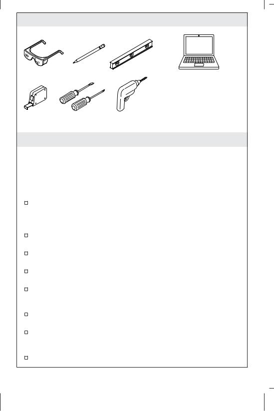
Tools and Materials
Computer or Tablet
Plus:
• Router
• Internet Service
• 1" Hole Saw (Optional)
Before You Begin
IMPORTANT! To access the controller Web pages for system setup, the controller and a computer or tablet must be connected to the same router.
NOTE: Internet access is required for downloading the latest software for system components.
Read these instructions and determine all components and installation locations before beginning installation. For shower configuration options, refer to the guide found on the product page at www.us.kohler.com.
The controller comes equipped with rubber feet for placement on a shelf or countertop.
The controller can be mounted vertically or horizontally and is designed to fit within a 2x4 stud cavity.
If mounting within a stud cavity, an access panel must be provided for servicing. The cavity must be free of insulation.
A qualified electrician should install a 15 A 120 V GFCI electrical outlet, within the stud framing, in close proximity to the controller.
If possible, install the electrical outlet prior to installing the controller.
An Ethernet cable is provided to connect the controller to a router. If the router is not within 25’ (7.6 m) of the controller, obtain a longer Ethernet cable or add an extension cable.
This product complies with UL, CSA, FCC, and IC.
1218131-2-A |
4 |
Kohler Co. |

Power Supply |
Internet |
|
|
Service |
|
72" (1.8 m) Cord |
48" |
|
|
(1219 mm) |
|
|
Cord |
|
Controller |
Router |
Computer |
|
or Tablet |
|
25' (7.6 m) Ethernet Cable |
|
|
|
Digital Valve |
|
Digital |
|
|
Valve |
|
|
Water Inlets Shower Accessories |
Interfaces |
1. Preparation
NOTE: The controller powers the interface(s) and controls system components such as digital mixing valve(s).
Your system can be set up to use three interfaces. One interface, installed inside the shower, is required.
Determine the locations of all components, including shower accessories. For pre-programmed shower configurations, refer to the guide found on the product page at www.us.kohler.com.
Refer to the installation guides packed with each product for specific installation needs.
Before Operating the System For the First Time:
Download and install the latest software for connected components. This may take an hour or more to complete based on system configuration and internet connection speed. Do not disconnect the power from the controller during software download and installation.
Kohler Co. |
5 |
1218131-2-A |

 4" (102 mm)
Drill 1" (25 mm) holes.
5/16" |
5-1/8" |
(130 mm) |
|
(8 mm) |
|
Power
Supply
Screw
|
Outlet |
|
Mounting |
Drip Loop |
|
Holes |
||
Feet |
||
|
2. Install the Controller
CAUTION: Risk of product damage. The controller is rated to operate in temperatures up to 104°F (40°C). Do not install near heat sources (such as radiators or under whirlpool surrounds) or in any location where the temperature may exceed 104°F (40°C).
NOTE: The controller comes equipped with rubber feet for placement on a shelf, or it can be installed to a vertical surface using the mounting holes.
The controller is designed to fit within a 2x4 stud cavity. The cavity must be free of insulation.
Installation In a Stud Cavity
Install a vertical surface between the studs.
Install four drywall screws according to the dimensions above. The screws should protrude 5/16″ (8 mm).
Install a 120 V GFCI electrical outlet within the stud framing, in close proximity to the controller.
1218131-2-A |
6 |
Kohler Co. |
Install the Controller (cont.)
NOTE: The power supply should be placed on a horizontal surface.
Do not secure the power supply to any surface.
Install a horizontal board to accommodate the power supply. Ensure the cord can be routed to the electrical outlet without being pinched.
Using a hole saw, drill 1″ (25 mm) holes through the studs at the top and bottom of the wall cavity to allow proper air flow.
Hook the controller onto the protruding screws.
Route the power supply from the controller to the electrical outlet.
Kohler Co. |
7 |
1218131-2-A |
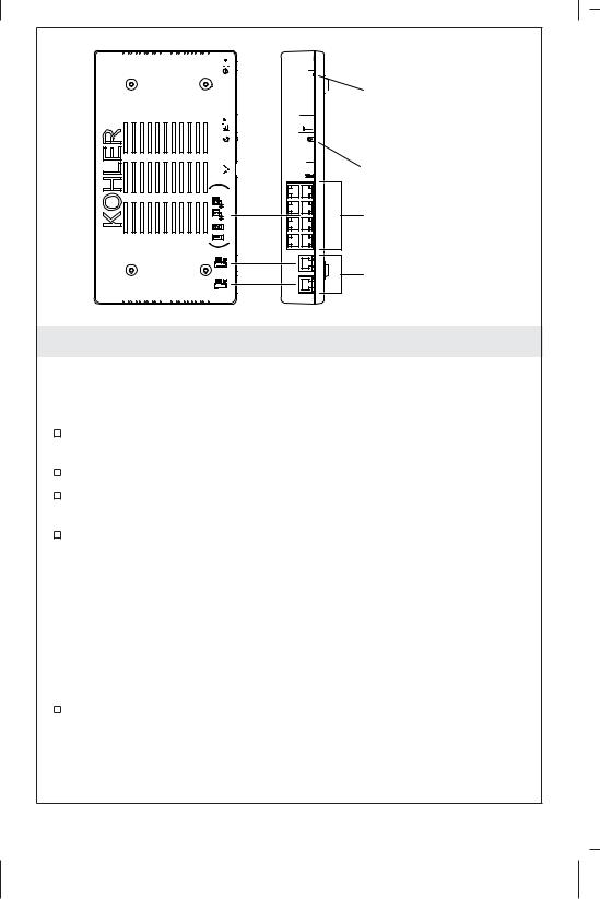


 Power Cord
 Status LED


 Ethernet


 Wi-Fi (Future Expansion)
Digital Interface(s) and
Optional Components
Digital Mixing Valve(s)
3. Connect the Components
IMPORTANT! Make drip loops in all cables.
IMPORTANT! Disconnect the power from the controller before connecting the cables.
If not already installed, install any digital interfaces, digital valves, and optional components for your system configuration.
Route all component cables to the controller location.
Gently press each connection into the proper port until it fully clicks in place.
Connect the power supply to the controller. Verify that the digital interface(s) illuminate.
Before Operating the System For the First Time:
Download and install the latest software for connected components. This may take an hour or more to complete based on system configuration and internet connection speed. Do not disconnect the power from the controller during software download and installation.
Refer to the ″Download/Install Software″ section for download instructions.
1218131-2-A |
8 |
Kohler Co. |
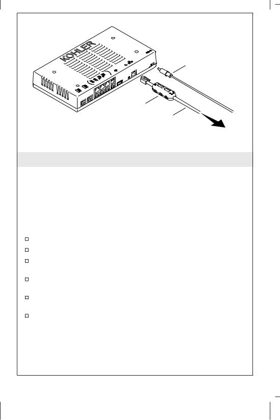
Power Cord
Ferrite
Ethernet
Cable To
Router
4. Download/Install Software
NOTICE: Software download and installation may take an hour or more to complete based on system configuration and internet connection speed. Do not disconnect the power from the controller during software download and installation.
NOTE: Internet service is required to receive the latest updates for system components. The components must be connected to the controller prior to software download.
Disconnect the power from the controller.
Make sure all system components are connected to the controller.
Attach the ferrite (provided) to the Ethernet cable, close to the end that will be connected to the controller.
Connect the Ethernet cable from the controller to a router with active internet service.
Reconnect the power supply to the controller. The controller will communicate with the router to receive an IP address.
Upon receiving an IP address, the controller will check for software updates for any connected components, and will automatically download and install the software. Do not disconnect the power from the controller during software download and installation.
Kohler Co. |
9 |
1218131-2-A |

|
|
about |
|
|
Controller |
|
|
Hardware: v0.0.0.0 |
system |
about |
Firmware: v0.0.0.0 |
IP: 0.0.0.0 |
||
settings |
|
MAC: 00:146F:0E:34:4A |
|
|
|
|
|
User Interface 1 |
|
|
OS: v0.0.0.0 |
|
|
Graphics: v0.0.0.0 |
|
|
Language: v0.0.0.0 |
|
|
TouchPanel: v0.0.0 |
 ok
ok 
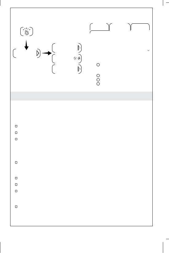
5. Obtain the IP Address
NOTE: System setup must be completed through the controller Web pages. The Web IP address is obtained from the interface.
From the [home] menu on the interface, touch the [settings] icon.
Go to [system], then to [about].
A pop-up screen will display current software information.
Copy the IP address from the screen.
NOTE: To access the Web pages, a computer or tablet must be connected to the same router as the controller.
On a computer or tablet connected to the same router as the controller, open a browser and enter the IP address into the search field.
The controller Web page should appear in the browser, providing access to configure system settings.
1218131-2-A |
10 |
Kohler Co. |
|
Interface |
Web Page |
|
|
|
updates |
|
|
|
|
|
Control |
Settings |
Service |
settings |
Controller |
|
|
|
|
|
|
|
|
|
Interface |
Diagnostics |
Updates |
|
|
|
|
|
|
system |
Graphics |
|
|
|
|
OS |
Check for Updates |
||
|
|
|
|
|
updates |
|
|
|
|
|
|
|
|
Browse... |
|
ok |
Upload |
|
|
6. Software Updates
NOTE: The controller will check for software updates daily (around midnight), and will automatically download and install if needed. Software can also be updated manually from the interface or the controller Web pages.
From the Interface
On the [home] menu, touch the [settings] icon.
Go to [system], then to [updates].
A pop-up screen will indicate if updates are available for any connected system components.
From the Web Pages
On a computer or tablet connected to the same router as the controller, open a browser and enter the Web IP address. Refer to the ″Obtain the IP Address″ section of this guide.
Click on the [Service] tab, then on [Updates].
Click [Check for Updates] to download the latest software for any connected system components.
If updates are available, the controller will automatically download and install the software.
Kohler Co. |
11 |
1218131-2-A |
Interface |
|
|
|
|
|
|
Web Page |
|
|
|
|||||||
|
|
|
|
|
|
|
|
|
|
|
|||||||
|
|
|
|
|
Control |
|
|
Settings |
Service |
||||||||
settings |
|
|
|
|
|
|
|
|
|
|
|
|
|
|
|
||
|
|
|
|
System |
|
|
Users |
|
Interface |
|
Valve 1 |
||||||
|
|
|
|
|
|
|
|
||||||||||
|
|
|
|
|
|
|
|
||||||||||
display |
|
|
|
|
Available Shower Configurations |
||||||||||||
interface |
|
|
|
|
Custom |
|
|
|
|
|
|
|
|
|
|||
|
|
|
|
Date/Time |
|
|
|
|
|
|
|
|
|
||||
auto return |
|
|
|
|
|
|
|
|
|
|
|
|
|
|
|
||
|
|
|
|
|
|
|
|
|
|
|
|
|
|
||||
|
|
|
|
|
|
|
2014/1/20 12:40 P -0600 |
|
|
|
|||||||
|
|
|
|
|
|
|
Day Light Savings Time |
|
|
|
|||||||
start up |
|
|
|
|
Date Format |
|
|
|
|||||||||
|
|
|
|
|
|
|
|
|
|
||||||||
|
|
|
|
|
|
|
MM-DD-YYYY |
|
|
|
|||||||
|
|
|
|
|
|
|
DD-MM-YYYY |
|
|
|
|||||||
|
|
|
|
|
|
|
YYYY-MM-DD |
|
|
|
|||||||
|
|
|
|
|
|
|
|
|
|
|
|
|
|
|
|
|
|
7. General Settings
NOTE: Interface settings can be configured from the interface. Valve setup and other system settings must be configured from the controller Web pages.
From the Interface
On the [home] menu, touch the [settings] icon.
Go to [interface] to select general settings for the interface.
For more information about using the interface and its menus, refer to the online guide on the product page at www.us.kohler.com.
From the Web Pages
On a computer or tablet connected to the same router as the controller, open a browser and enter the Web IP address. Refer to the ″Obtain the IP Address″ section of this guide.
Click on the [Settings] tab, then on [System].
Select the general settings for your system.
User presets and additional interface settings can be configured from the Web pages. Click on the appropriate menu to access the options for those settings.
For valve setup, refer to the ″Valve Settings″ section of this guide.
1218131-2-A |
12 |
Kohler Co. |
Control |
Settings |
Service |
Control |
Settings |
Service |
|
System |
Users Interface Valve 1 |
System |
Users Interface Valve 1 Valve 2 |
|||
Available Shower Configurations |
Outlet 1 |
|
Outlet 2 |
|||
Custom |
|
|
|
|||
|
|
|
Massage |
|
||
|
|
|
|
|
||
|
|
|
|
Default |
|
|
|
|
|
|
Auto Purge |
||
|
|
|
Outlet 4 |
|
Outlet 5 |
|
|
|
|
|
Massage |
|
|
|
|
|
|
Default |
|
|
|
|
|
|
Auto Purge |
||
Feature Enable |
|
Temperature |
|
|||
|
Default Temperature |
38.0 |
||||
Please read owner’s manual regarding possible |
||||||
Max Temperature |
46.0 |
|||||
risks associated with these features |
||||||
Steam |
|
|
Auto Purge |
7 Seconds |
||
Massage |
|
|
Cold Water |
|
5 Minutes |
|
Spa |
|
|
|
|
|
|
Swap Valves 1 and 2
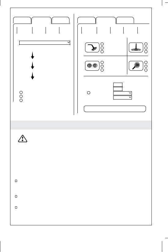
8. Valve Settings
NOTICE TO INSTALLER:
WARNING: Risk of personal injury. Safety precautions must be followed when using shower features such as
[Massage] and [Spa]. Before enabling, ensure the homeowner has read the associated risks listed in the guides for these features.
Pre-Programmed Shower Configurations
NOTE: Pre-programmed shower configurations are outlined in the guide found on the product page at www.us.kohler.com.
If components are installed for pre-programmed shower configurations, the components can be automatically populated on the Web pages.
Shower configurations are available based on the number of valves connected to the controller.
To populate pre-programmed configurations, select the appropriate dropdown option in the [Available Shower Configurations] field. The shower components will appear in the outlet options on the valve menus.
Kohler Co. |
13 |
1218131-2-A |
Valve Settings (cont.)
To enable shower features, such as [Massage], go to the [Settings] tab, then click on [System]. Safety instructions for each feature must be read by the homeowner before it is enabled. Refer to the guide for each feature.
Custom Shower Configurations
NOTE: Custom shower components will need to be selected manually on the Web page valve menus.
To check or configure valve settings, go to the [Settings] tab, then click on [Valve 1].
Select the settings for each shower outlet for your system configuration.
If applicable, click on [Valve 2] to select the outlets for the second valve.
Complete the Installation
Once components have been configured, test for functionality. Verify that each component is operating as intended.
For troubleshooting information for each system component, refer to the guide found on the product page at www.us.kohler.com.
Troubleshooting
IMPORTANT! Turn off the power before performing any maintenance.
NOTE: For service parts information, visit your product page at www.kohler.com/serviceparts.
This troubleshooting guide is for general aid only. For service and installation issues or concerns, call 1-800-4KOHLER.
Controller Troubleshooting Table |
|
|
Symptoms |
Probable Cause |
Recommended Action |
1. System stops |
A. System failure. |
A. Reboot the controller |
working and |
|
by disconnecting the |
the status LED |
|
AC power from the |
is solid red. |
|
wall outlet. If the |
|
|
status LED remains a |
|
|
solid red after reboot, |
|
|
replace the controller. |
|
|
|
|
|
|
1218131-2-A |
14 |
Kohler Co. |

Troubleshooting (cont.) |
|
|
|
||
|
|
|
|
||
Controller Troubleshooting Table |
|
|
|||
Symptoms |
Probable Cause |
Recommended Action |
|||
2. |
System stops |
A. |
Power supply |
A. |
Reboot the controller |
|
working and |
|
failure. |
|
by disconnecting the |
|
the Status LED |
|
|
|
AC power from the |
|
is OFF. |
|
|
|
wall outlet. If there is |
|
|
|
|
|
no change after |
|
|
|
|
|
reboot, replace the |
|
|
|
|
|
power supply. |
|
|
B. |
Incorrect wiring of |
B. |
Verify that the |
|
|
|
the AC power |
|
controller was |
|
|
|
supply. |
|
installed per the |
|
|
|
|
|
installation manual. |
|
|
|
|
|
Make sure AC power |
|
|
|
|
|
is present at the |
|
|
|
|
|
outlet the controller |
|
|
|
|
|
is plugged into. |
3. |
Components |
A. |
Damaged cables or |
A. |
Check all wiring |
|
are sometimes |
|
incorrect cable |
|
connections. |
|
not on the |
|
installation. |
|
|
|
menu, even |
|
|
|
|
|
though they |
|
|
|
|
|
are connected |
|
|
|
|
|
to the |
|
|
|
|
|
controller. |
|
|
|
|
|
|
B. |
Power fluctuation. |
B. |
Verify that the |
|
|
|
|
|
devices are |
|
|
|
|
|
connected to a stable |
|
|
|
|
|
power supply. |
|
|
C. The device is not |
C. |
See peripheral device |
|
|
|
|
installed correctly. |
|
owners manual. |
|
|
|
|
||
Interface Troubleshooting Table |
|
|
|||
Symptoms |
Probable Cause |
Recommended Action |
|||
1. |
Interface is not |
A. |
Controller is not |
A. |
Plug the controller |
|
lit. |
|
plugged into the |
|
into an electrical |
|
|
|
electrical outlet. |
|
outlet. |
|
|
B. |
Interface cable |
B. |
Check all interface |
|
|
|
connections may |
|
cable connections. |
|
|
|
be loose or |
|
|
|
|
|
disconnected. |
|
|
|
|
C. |
Circuit breaker has |
C. |
Reset the circuit |
|
|
|
been tripped. |
|
breaker. |
|
|
|
|
|
|
|
|
|
|
|
|
Kohler Co. |
|
15 |
|
1218131-2-A |
|
Troubleshooting (cont.)
Interface Troubleshooting Table
Symptoms |
Probable Cause |
Recommended Action |
||
|
D. The controller may |
D. Disconnect and |
||
|
|
require resetting. |
|
reconnect the |
|
|
|
|
controller power |
|
|
|
|
supply from the |
|
|
A ″cross-over″ |
|
electrical outlet. |
|
E. |
E. |
Connect the interface |
|
|
|
cable or coupler |
|
to the controller |
|
|
was used to |
|
using a |
|
|
connect the |
|
″straight-through″ |
|
|
interface to the |
|
cable or coupler. |
|
|
controller. |
|
|
|
F. |
If none of the |
F. |
Contact your Kohler |
|
|
recommended |
|
Co. Authorized |
|
|
actions for the |
|
Service |
|
|
above issues |
|
Representative. |
|
|
correct the |
|
|
|
|
symptom, the |
|
|
|
|
interface or |
|
|
|
|
controller requires |
|
|
|
|
servicing. |
|
|
2. The interface |
A. |
Interface cable |
A. |
Check all interface |
power |
|
connections may |
|
cable connections. |
indicator is lit, |
|
be loose. |
|
|
but the system |
|
|
|
|
will not turn |
|
|
|
|
on. |
|
|
|
|
|
B. |
The interface cable |
B. |
Replace the cable or |
|
|
or coupler is |
|
coupler. |
|
|
damaged. |
|
|
|
C. |
If the above |
C. |
Contact your Kohler |
|
|
recommended |
|
Co. Authorized |
|
|
action does not |
|
Service |
|
|
correct the |
|
Representative. |
|
|
symptom, the |
|
|
|
|
interface or |
|
|
|
|
controller requires |
|
|
|
|
servicing. |
|
|
|
|
|
|
|
Warranty
KOHLER® Electronic Faucets, Valves and Controls
FIVE-YEAR LIMITED WARRANTY
Kohler Co. warrants that its electronic faucets, valves and controls will
1218131-2-A 16 Kohler Co.

Warranty (cont.)
be free of defects in material and workmanship during normal residential use for five years from the date the product is installed. This warranty applies only to electronic faucets, valves and controls installed in the United States of America, Canada and Mexico (″North America″).
If a defect is found in normal residential use, Kohler Co. will, at its election, repair, provide a replacement part or product, or make appropriate adjustment where Kohler Co.’s inspection discloses any such defect. Damage caused by accident, misuse, or abuse is not covered by this warranty. Improper care and cleaning will void the warranty*. Proof of purchase (original sales receipt) must be provided to Kohler Co. with all warranty claims. Kohler Co. is not responsible for labor charges, installation, or other incidental or consequential costs other than those noted above. In no event shall the liability of Kohler Co. exceed the purchase price of the faucet, valve or control.
If the electronic faucets, valves or controls are used commercially or are installed outside of North America, Kohler Co. warrants that the faucet, valve or control will be free from defects in material and workmanship for one (1) year from the date the product is installed, with all other terms of this warranty applying except duration.
If you believe that you have a warranty claim, contact your Home Center, Dealer, Plumbing Contractor or E-tailer. Please be sure to provide all pertinent information regarding your claim, including a complete description of the problem, the product, model number, the date the product was purchased, from whom the product was purchased and the installation date. Also include your original invoice. For other information, or to obtain the name and address of the service and repair facility nearest you, write Kohler Co., Attn: Customer Care Center, Kohler, Wisconsin 53044 USA, or by calling 1-800-4-KOHLER (1-800-456-4537) from within the USA and Canada, and 001-800-456-4537 from within Mexico, or visit www.kohler.com within the USA, www.ca.kohler.com from within Canada, or www.mx.kohler.com in Mexico.
THE FOREGOING WARRANTIES ARE IN LIEU OF ALL OTHER WARRANTIES, EXPRESS OR IMPLIED, INCLUDING BUT NOT LIMITED TO THE IMPLIED WARRANTIES OF MERCHANTABILITY AND FITNESS FOR A PARTICULAR PURPOSE.
KOHLER CO. AND/OR SELLER DISCLAIM ANY LIABILITY FOR SPECIAL, INCIDENTAL OR CONSEQUENTIAL DAMAGES. Some states/provinces do not allow limitations on how long an implied warranty lasts or the exclusion or limitation of such damages, so
Kohler Co. |
17 |
1218131-2-A |
Warranty (cont.)
these limitations and exclusions may not apply to you. This warranty gives the consumer specific legal rights. You may also have other rights that vary from state/province to state/province. This warranty is to the original consumer purchaser only, and excludes product damage due to installation error, product abuse, or product misuse, whether performed by a contractor, service company, or the consumer.
This is Kohler Co.’s exclusive written warranty.
*Never use cleaners containing abrasive cleansers, ammonia, bleach, acids, waxes, alcohol, solvents or other products not recommended for chrome. This will void the warranty.
1218131-2-A |
18 |
Kohler Co. |
 Loading...