


Installation and Care Guide
Electronic Kitchen Faucet
K-72218
1186051-2-E
IMPORTANT INSTRUCTIONS
WARNING: When using electrical products, basic precautions should always be followed, including the following:
DANGER: Risk of electric shock. Connect only to a circuit protected by a Ground-Fault Circuit-Interrupter (GFCI)*.
WARNING: Risk of electric shock. Grounding is required. A licensed electrician should make all electrical connections.
WARNING: Risk of electric shock. Disconnect power before servicing.
WARNING: Risk of injury or property damage. Please read all instructions thoroughly before beginning installation.
CAUTION: Risk of property damage. The faucet spout contains a magnet. Do not allow items susceptible to electromagnetic damage to come into close proximity to the spout.
NOTICE: Follow all plumbing, electrical, and building codes.
*Outside North America, this device may be known as a Residual Current Device (RCD).
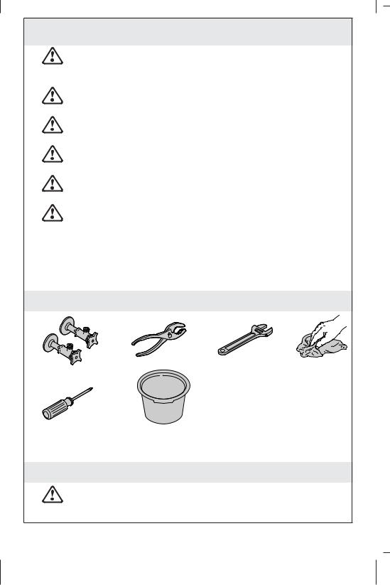
Tools
3/8" |
Rags |
|
Plus: |
|
• Unswitched Electrical Outlet |
Phillips Screwdriver |
Bucket |
Important Information
CAUTION: Risk of fresh water contamination. This faucet contains back-siphonage protection. Do not remove any internal components.
1186051-2-E |
2 |
Kohler Co. |

Important Information (cont.)
CAUTION: Risk of product damage. This product contains sensitive electronic components. Do not store open containers of chemical or cleaning products near this product. Cleaning rags or sponges must be rinsed with fresh water before storage.
NOTICE: Do not use a switch-controlled outlet (typically used for garbage disposals) to provide power to the faucet.
Observe all local plumbing and building codes.
Provide a constant unswitched 120 VAC electrical outlet located below the sink within 5’ (1.5 m) of the control box.
Shut off the water supply.
For new installations, assemble the faucet to the sink before installing the sink.
For uneven mounting surfaces (such as tile grout lines), apply a suitable sealant under the faucet. Do not use petroleum-based sealant.
Kohler Co. |
3 |
1186051-2-E |

Escutcheon
Shank
Spray |
1/4" |
(6 mm) |
|
Hose |
|
Washer
Ring
1. Install the Faucet
NOTE: Handle orientation is designed to be on the right. Thread the screws into the ring 1/4″ (6 mm) past the surface.
Insert the faucet through the mounting surface with the handle on the right.
Pull the sprayhead out and rest it in the sink basin. Do not pull the end of the spray hose into the shank.
From under the sink, push the spray hose up to the shank.
Slide the washer over the hoses and wires, then up onto the shank.
Slide the ring over the hoses and wires, then up to the shank.
Thread the ring onto the shank until the washer contacts the underside of the sink.
Adjust the ring to align the screws with the front and back of the faucet.
Use a Phillips screwdriver to securely tighten the screws.
Pull the spray hose end down, away from the shank.
Slide the sprayhead back into the spout.
1186051-2-E |
4 |
Kohler Co. |

Ø 3" (76 mm) |
Solenoid |
Min |
Supply |
Outlet Hose |
|
|
Hose |
|
Clamp
Weight
2. Connect the Hoses
CAUTION: Risk of restricted water flow and product damage.
Supply hoses must not be taut, kinked, or twisted during installation. If the supply hoses must be coiled, maintain an inside diameter of 3″ (78 mm).
Connect the Supplies
Assemble the outlet hose to the faucet.
Connect and tighten the supply hoses to the supply stops.
Place a bucket under the outlet hose.
Turn on the water supplies.
Flush hot and cold water into a bucket for 1 minute to remove any debris.
Connect the Spray Hose
NOTICE: The weight must be installed onto the spray hose to act as a pull stop and to prevent kinking damage.
Slide the weight, then the clamp onto the spray hose.
Kohler Co. |
5 |
1186051-2-E |
Connect the Hoses (cont.)
TIP: Use a pliers to expand the clamp over the hose end.
Attach the spray hose to the outlet fitting on the solenoid. Ensure the hose is completely engaged into the fitting.
Remove the protective cap.
Attach the outlet hose to the solenoid.
1186051-2-E |
6 |
Kohler Co. |

|
Bracket |
Solenoid |
Tab |
|
|
|
Wire |
Cover
Power |
Apply grease. |
Cord |
|
Handle Switch
Solenoid
LED Sensor
3. Install the Valve
CAUTION: Risk of restricted waterflow. The outlet hose must not be taut or kinked when installed. Locate the solenoid valve within 7″ (178 mm) to 8″ (203 mm) of the faucet centerline.
Mount the Bracket
NOTE: Locate the solenoid valve within 7″ (178 mm) to 8″ (203 mm) from the faucet centerline. Allow adequate clearance for servicing.
NOTE: The mounting bracket should be secured with two suitable fasteners (not supplied) based on the type and thickness of the cabinet or wall material.
Fasten the mounting bracket vertically to the cabinet or wall.
Connect the Wires
NOTE: The solenoid can be positioned right or left. Remove the appropriate tab on the cover.
Kohler Co. |
7 |
1186051-2-E |
Install the Valve (cont.)
Apply grease (provided) to the sensor socket located on the circuit board inside the cover. This will provide additional corrosion protection.
Connect the handle switch wire and sensor wire from the faucet to the circuit board.
Connect the power cord to the circuit board.
Fit the cover over the solenoid.
Connect the solenoid wire to the circuit board.
Plug the power cord into an unswitched 120 VAC outlet. The LED on the circuit board will illuminate.
Secure the assembly to the mounting bracket with the two screws provided.
Test activation of the sensor. Refer to the ″Faucet Operation″ section.
1186051-2-E |
8 |
Kohler Co. |


 2" (51 mm) – 3" (76 mm)
4. Complete the Installation
Position the Weight
Position the weight between 2″ (51 mm) and 3″ (76 mm) from the cabinet floor.
Secure the clamp around the spray hose just below the weight. Extend and retract the spray hose to check for smooth operation.
Check for Leaks
Ensure all connections are tight.
Test the faucet for proper operation. Refer to the ″Faucet Operation″ section.
Check all connections for leaks. Make adjustments as needed.
Kohler Co. |
9 |
1186051-2-E |

Manual Override
Sensor
Sensor |
Handle LED |
LEDs |
|
|
Open Position |
Faucet Operation
Rotate the handle outward to the open position to start water flow. The handle LED will illuminate to indicate that the sensor is functioning.
Adjust the handle to the desired water temperature.
Wave your hand under the spout to turn the water OFF.
Wave your hand under the spout again to restart the water flow.
NOTE: Some objects that are clear and certain colors are not detectable by the sensor. Always use your hand for sensor testing.
If needed, refer to the ″Handle LED Adjustment″ section for more information.
NOTE: For extended periods of nonuse, the handle should be returned to the closed (upright) position. The handle LED will turn OFF, indicating that water flow is not available.
LED Indicators
Handle LED: Illuminates when the sensor is active.
Circuit board LED: Indicates there is power to the circuit board.
NOTE: The sensor LEDs are only visible inside the spout when the spray hose is extended.
Green sensor LED: Indicates there is power to the sensor.
1186051-2-E |
10 |
Kohler Co. |
Faucet Operation (cont.)
Yellow sensor LED: Illuminates when an object has been detected by the sensor.
Features
Automatic shut-off: After 4 minutes of inactivity, the water will automatically shut OFF.
Sensor override: In the event of power loss, the sensor function can be bypassed by turning in the override feature on the solenoid valve. The faucet can then be operated manually.
Kohler Co. |
11 |
1186051-2-E |

Closed
Position
LED
Open Position
Setscrew
Handle LED Adjustment
NOTE: The LED should turn ON as the handle is rotated open, and OFF when the handle is in the upright (closed) position. Use a 5/64″ hex wrench to adjust the valve setscrew as needed.
IMPORTANT! Do not apply upward pressure to the valve setscrew while making adjustments.
LED is ON when the handle is closed: Tighten the valve setscrew until the LED turns OFF. Then tighten the setscrew an additional 1/4 turn.
Handle does not return to the upright position: Loosen the valve setscrew until the handle rotates to the full upright (closed) position and the LED turns ON. Then tighten the setscrew until the LED turns OFF, plus an additional 1/4 turn.
Water does not fully shut off: Loosen the valve setscrew until the handle rotates to the full upright (closed) position and the LED turns ON. Then tighten the setscrew until the LED turns OFF, plus an additional 1/4 turn.
1186051-2-E |
12 |
Kohler Co. |

Supply
Hose
Screen |
Screen |
Screen
Sprayhead |
Outlet |
|
Hose |
||
|
Cleaning the Screens
Sprayhead Screen
Turn the handle to the closed position.
Disconnect the nut at the end of the spray hose.
Remove and clean the screen inside the spray hose.
Reinsert the screen and reconnect the spray hose.
Solenoid Inlet Screen
Turn the handle to the closed position.
Disconnect the outlet hose from the solenoid.
Remove and clean the inlet screen inside the solenoid.
Reinstall the inlet screen and reconnect the outlet hose.
Supply Hose Screen
Turn off the water supplies.
Disconnect the supply hose from the supply stop.
Remove and clean the screen inside the hose inlet.
Reinsert the screen and reconnect the supply hose to the stop. Turn on the water supplies.
Kohler Co. |
13 |
1186051-2-E |

Care and Cleaning
For best results, keep the following in mind when caring for your KOHLER product:
•Use a mild detergent such as liquid dishwashing soap and warm water for cleaning. Do not use abrasive cleaners that may scratch or dull the surface.
•Carefully read the cleaner product label to ensure the cleaner is safe for use on the material.
•Always test your cleaning solution on an inconspicuous area before applying to the entire surface.
•Do not allow cleaners to sit or soak on the surface.
•Wipe surfaces clean and rinse completely with water immediately after cleaner application. Rinse and dry any overspray that lands on nearby surfaces.
•Use a soft, dampened sponge or cloth. Never use an abrasive material such as a brush or scouring pad to clean surfaces.
For detailed cleaning information and products to consider, visit www.kohler.com/clean. To order Care & Cleaning information, call 1-800-456-4537.
Warranty
KOHLER® Electronic Faucets, Valves and Controls
FIVE-YEAR LIMITED WARRANTY
Kohler Co. warrants that its electronic faucets, valves and controls will be free of defects in material and workmanship during normal residential use for five years from the date the product is installed. This warranty applies only to electronic faucets, valves and controls installed in the United States of America, Canada and Mexico (″North America″).
If a defect is found in normal residential use, Kohler Co. will, at its election, repair, provide a replacement part or product, or make appropriate adjustment where Kohler Co.’s inspection discloses any such defect. Damage caused by accident, misuse, or abuse is not covered by this warranty. Improper care and cleaning will void the warranty*. Proof of purchase (original sales receipt) must be provided to Kohler Co. with all warranty claims. Kohler Co. is not responsible for labor charges, installation, or other incidental or consequential costs other than those noted above. In no event shall the liability of Kohler Co. exceed the purchase price of the faucet, valve or control.
1186051-2-E |
14 |
Kohler Co. |
Warranty (cont.)
If the electronic faucets, valves or controls are used commercially or are installed outside of North America, Kohler Co. warrants that the faucet, valve or control will be free from defects in material and workmanship for one (1) year from the date the product is installed, with all other terms of this warranty applying except duration.
If you believe that you have a warranty claim, contact your Home Center, Dealer, Plumbing Contractor or E-tailer. Please be sure to provide all pertinent information regarding your claim, including a complete description of the problem, the product, model number, the date the product was purchased, from whom the product was purchased and the installation date. Also include your original invoice. For other information, or to obtain the name and address of the service and repair facility nearest you, write Kohler Co., Attn: Customer Care Center, Kohler, Wisconsin 53044 USA, or by calling 1-800-4-KOHLER (1-800-456-4537) from within the USA and Canada, and 001-800-456-4537 from within Mexico, or visit www.kohler.com within the USA, www.ca.kohler.com from within Canada, or www.mx.kohler.com in Mexico.
THE FOREGOING WARRANTIES ARE IN LIEU OF ALL OTHER WARRANTIES, EXPRESS OR IMPLIED, INCLUDING BUT NOT LIMITED TO THE IMPLIED WARRANTIES OF MERCHANTABILITY AND FITNESS FOR A PARTICULAR PURPOSE.
KOHLER CO. AND/OR SELLER DISCLAIM ANY LIABILITY FOR SPECIAL, INCIDENTAL OR CONSEQUENTIAL DAMAGES. Some states/provinces do not allow limitations on how long an implied warranty lasts or the exclusion or limitation of such damages, so these limitations and exclusions may not apply to you. This warranty gives the consumer specific legal rights. You may also have other rights that vary from state/province to state/province. This warranty is to the original consumer purchaser only, and excludes product damage due to installation error, product abuse, or product misuse, whether performed by a contractor, service company, or the consumer.
This is Kohler Co.’s exclusive written warranty.
*Never use cleaners containing abrasive cleansers, ammonia, bleach, acids, waxes, alcohol, solvents or other products not recommended for chrome. This will void the warranty.
Troubleshooting
Kohler Co. |
15 |
1186051-2-E |

Troubleshooting (cont.)
CAUTION: Risk of product damage. This product contains sensitive electronic components. Use care not to damage pins and connectors during troubleshooting.
CAUTION: Risk of product damage. Do not insert anything other than the sensor wire into the sensor wire connector (phone jack) on the circuit board.
NOTE: For service parts information, visit your product page at www.kohler.com.
Faucet Troubleshooting Table
Symptoms |
Probable Causes |
Recommended Action |
|
|||
1. |
No water flow. |
A. |
The supply |
A. |
Confirm the supply |
|
|
|
|
stops are |
|
stops are open. |
|
|
|
|
closed. |
|
|
|
|
|
B. |
Handle is in |
B. |
Rotate the handle to the |
|
|
|
|
the closed |
|
open position. Refer to |
|
|
|
|
position. |
|
the ″Faucet Operation″ |
|
|
|
|
|
|
section. |
|
|
|
C. |
The hot |
C. |
Confirm the supply |
|
|
|
|
and/or cold |
|
hoses are not kinked. If |
|
|
|
|
supply hose |
|
coiled, maintain an |
|
|
|
|
is kinked. |
|
inside diameter of 3″ |
|
|
|
|
|
|
(76 mm). |
|
|
|
D. The outlet |
D. Confirm the solenoid |
|||
|
|
|
hose is |
|
valve is located within |
|
|
|
|
kinked. |
|
7″ (178 mm) to 8″ (203 |
|
|
|
|
|
|
mm) from the faucet |
|
|
|
|
|
|
base. |
|
|
|
E. |
Handle LED |
E. |
Refer to the ″Handle |
|
|
|
|
is not lit. |
|
Switch Troubleshooting |
|
|
|
|
|
|
Table.″ |
|
|
|
F. |
Sensor LED |
F. |
Refer to the ″Sensor |
|
|
|
|
is not lit. |
|
Troubleshooting Table.″ |
|
|
|
G. One or more |
G. |
Refer to the ″Cleaning |
|
|
|
|
|
screens are |
|
the Screens″ section. |
|
|
|
|
clogged. |
|
|
|
2. |
Low water flow. |
A. |
The supply |
A. |
Confirm the supply |
|
|
|
|
stops are |
|
stops are fully open. |
|
|
|
|
partially |
|
|
|
|
|
|
closed. |
|
|
|
|
|
B. |
Handle is |
B. |
Rotate the handle to the |
|
|
|
|
partially |
|
full open position. |
|
|
|
|
closed. |
|
|
|
|
|
|
|
|
|
|
|
|
|
|
|
|
|
1186051-2-E |
|
16 |
|
Kohler Co. |
||

Troubleshooting (cont.) |
|
|
|
||
|
|
|
|
||
Faucet Troubleshooting Table |
|
|
|||
Symptoms |
Probable Causes |
Recommended Action |
|||
|
|
C. |
The hot |
C. |
Confirm the supply |
|
|
|
and/or cold |
|
hoses are not kinked or |
|
|
|
supply hose |
|
twisted. If coiled, |
|
|
|
is kinked or |
|
maintain an inside |
|
|
|
twisted. |
|
diameter of 3″ (76 mm). |
|
|
D. The outlet |
D. |
Confirm the solenoid |
|
|
|
|
hose is |
|
valve is located within |
|
|
|
kinked. |
|
7″ (178 mm) to 8″ (203 |
|
|
|
|
|
mm) from the faucet |
|
|
|
|
|
base. |
|
|
E. |
One or more |
E. |
Refer to the ″Cleaning |
|
|
|
screens are |
|
the Screens″ section. |
|
|
|
clogged. |
|
|
|
|
F. |
Cracked |
F. |
Replace the solenoid |
|
|
|
diaphragm. |
|
valve assembly. |
3. |
Poor spray |
A. |
The spray |
A. |
Rub your finger over |
|
pattern. |
|
nozzles are |
|
the nozzles with water |
|
|
|
clogged. |
|
running to dislodge |
|
|
|
|
|
debris. |
4. |
Circuit board LED |
A. |
No power to |
A. |
Check the power |
|
is not lit. |
|
the circuit |
|
supply connections to |
|
|
|
board. |
|
the circuit board. |
|
|
B. |
Power cord is |
B. |
Plug the power cord |
|
|
|
plugged into |
|
into an unswitched 120 |
|
|
|
a switched |
|
VAC outlet (test the |
|
|
|
outlet. |
|
outlet with a radio or |
|
|
|
|
|
other device). Confirm |
|
|
|
|
|
the circuit board LED |
|
|
|
|
|
illuminates. |
5. |
Water drip or |
A. |
Manual |
A. |
Turn the white manual |
|
trickle when |
|
override is |
|
override clockwise until |
|
faucet is not in |
|
partially |
|
it stops; then turn it |
|
use. |
|
engaged. |
|
counterclockwise until |
|
|
|
|
|
the water drip stops. |
|
|
|
|
|
|
|
|
|
|
|
|
Kohler Co. |
|
17 |
|
1186051-2-E |
|

Troubleshooting (cont.) |
|
|
|
||
|
|
|
|
||
Solenoid Troubleshooting Table |
|
|
|||
Symptoms |
Probable Causes |
Recommended Action |
|||
1. |
Water leaking |
A. Hose |
A. CAUTION: Risk of |
||
|
from the valve. |
|
connections |
|
personal injury or |
|
|
|
are not |
|
product damage. Turn |
|
|
|
secure. |
|
off the main power and |
|
|
|
|
|
water supply. Check all |
|
|
|
|
|
connections. Make |
|
|
|
|
|
adjustments as needed. |
|
|
B. |
Internal leak. |
B. |
Replace the solenoid |
|
|
|
|
|
valve assembly. |
2. |
No audible ″click″ |
A. |
Loose |
A. |
Check solenoid wire |
|
when solenoid is |
|
solenoid wire |
|
connection to the circuit |
|
activated. |
|
connection. |
|
board. |
|
|
B. |
Solenoid |
B. |
Replace the solenoid |
|
|
|
valve is not |
|
valve assembly. |
|
|
|
functioning. |
|
|
|
|
|
|
||
Handle Switch Troubleshooting Table |
|
|
|||
Symptoms |
Probable Causes |
Recommended Action |
|||
1. Handle LED is lit |
A. |
Valve |
A. |
Refer to the ″Handle |
|
|
when the handle |
|
setscrew |
|
LED Adjustment″ |
|
is closed. |
|
needs |
|
section. |
|
|
|
adjustment. |
|
|
2. |
Handle does not |
A. |
Valve |
A. |
Refer to the ″Handle |
|
return to the |
|
setscrew |
|
LED Adjustment″ |
|
upright position. |
|
needs |
|
section. |
|
|
|
adjustment. |
|
|
3. |
Water does not |
A. |
Valve |
A. |
Refer to the ″Handle |
|
fully shut off. |
|
setscrew |
|
LED Adjustment″ |
|
|
|
needs |
|
section. |
|
|
|
adjustment. |
|
|
4. |
Handle LED does |
A. |
Loose handle |
A. |
Check handle switch |
|
not illuminate |
|
switch wire |
|
wire connection to the |
|
when the handle |
|
connection. |
|
circuit board. |
|
is rotated open. |
B. |
Circuit board |
B. |
Replace the cover |
|
|
|
is not |
|
assembly. |
|
|
|
functioning |
|
|
|
|
|
correctly. |
|
|
|
|
|
|
|
|
|
|
|
|
|
|
1186051-2-E |
|
18 |
|
Kohler Co. |
|
 Loading...