


Installation and Care Guide
Bath and Shower Valve
K-11748-K |
|
K-11748-KS |
M product numbers are for Mexico (i.e. K-12345M) Los números de productos seguidos de
M corresponden a México (Ej. K-12345M)
Français, page “Français-1” Español, página “Español-1”
1128093-2-E
IMPORTANT INSTRUCTIONS
READ AND SAVE FOR THE
CONSUMER
WARNING: Risk of scalding or other severe injury.
•Before completing installation, the installer must set the maximum water temperature setting of this valve to minimize the risks associated with scalding hazards according to ASTM F 444.
•Do not install a shut-off device on either outlet of this valve. The installation of any such device may create a cross-flow condition at the valve and affect the water temperature.
•Factors that change the temperature of the water supplied to the valve, such as seasonal water temperature changes, and water heater replacement or servicing, will change the maximum water temperature supplied by the valve and may create a scalding hazard. The pressure-balancing valve will not compensate for changes in the water supply temperature; adjust the maximum water temperature setting of this pressure-balancing valve when such changes occur.
•Pressure-balancing valves may not provide protection against scalding if there is a failure of other temperature-limiting devices elsewhere in the plumbing system.
NOTICE: Only apply silicone based lubricants to these valves. Do not use petroleum based lubricants. Petroleum based lubricants will harm the O-rings, seals, and plastic components.
The installer is responsible for installing the valve and adjusting the maximum water temperature of this pressure-balancing valve according to instructions.
This valve meets or exceeds ANSI A112.18.1 and ASSE 1016.
If you do not understand any of the installation or temperature adjustment instructions in this document, in the United States please contact our Customer Care Center at 1-800-4KOHLER. Outside the U.S., please contact your distributor.
IMPORTANT NOTICE TO INSTALLERS! Please fill in the blanks in the information box below and on the valve label. Retain this information for future reference.
1128093-2-E |
2 |
Kohler Co. |

IMPORTANT INSTRUCTIONS (cont.)
NOTICE TO HOMEOWNERS! This device has been preset by
_______________________ of _______________________________ to ensure a safe maximum temperature. Any change in the setting may raise the discharge temperature above the limit considered safe, and lead to scalds.
Date: ______________
Tools
5/64"
Hex Wrench
Solder |
Sealant Tape Hacksaw or Tubing Cutter Strap Wrench |
Important Information
WARNING: Risk of scalding. High water temperature can cause severe burns. Set the water temperature at or below 120°F (49°C) following the adjustment procedure.
NOTICE: Do not force the handle in any direction. Forcing the handle will damage the valve.
NOTE: The primary outlet is the outlet that the water will flow from when the valve is turned on. Water will flow from the secondary outlet when the diverter is pressed.
This valve can be used for two different installation configurations: 1) Bath Spout (primary) with Showerhead or Handshower (secondary) and 2) Showerhead (primary) with Handshower (secondary). See the ″Installation Options″ section for example piping options. Follow only the instructions that apply to your chosen installation.
Kohler Co. |
3 |
1128093-2-E |

Important Information (cont.)
This valve can be used for thin and thick wall installations. Thin wall installations are typically fiberglass and acrylic. Thick wall installations are typically tile, plaster, marble, or other similar material.
Observe all local plumbing and building codes.
Shut off the water supply.
1128093-2-E |
4 |
Kohler Co. |

Installation Options
1 Bath as Primary Outlet |
2 Showerhead as |
|
Primary Outlet |
Preparation
Kohler Co. |
5 |
1128093-2-E |

Stop
Assembly
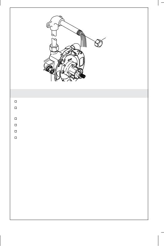
1. Prepare the Valve
IMPORTANT! The internal components of the valve will only need to be removed for back-to-back installations (reversed valve only) or installations that require soldering of connections.
NOTE: Only valves with stops will include the stop assembly.
Solder Installations Only
Remove the plaster guard (not shown).
Remove internal valve components as shown and set aside.
Back-to-Back Installations Only
Remove the plaster guard (not shown).
For the reversed valve, remove internal components as shown and set aside. The stop assembly does not need to be removed if soldering is not needed.
1128093-2-E |
6 |
Kohler Co. |

|
2-1/16" (52 mm) |
2x4 Bracing |
|
72" (1829 mm) – |
|
78" (1981 mm) |
Finished Wall |
To Floor |
|
(Typical) |
|
7" (178 mm) – |
2-3/4" (70 mm) |
18" (457 mm) |
Thin Wall |
[10" (254 mm) |
2-1/16" (52 mm) |
Recommended |
|
4" (102 mm) |
Finished |
|
|
|
Wall |
Cold Supply |
|
Hot Supply |
2-3/4" (70 mm) – |
|
3-1/2" (89 mm) |
|
Thick Wall |
2. Roughing-In
Showerhead/Bath Spout Installations
For Back-to-Back Installations: Proceed to the ″Install the Supply Piping and Valve, Back-to-Back″ section.
Route the supplies and install the valve. Refer to the roughing-in illustration for your installation.
NOTE: The position of the 2x4 bracing is dependent on the thickness of your finished wall.
Install 2x4 bracing behind the plate as shown.
Install bracing at the showerhead and bath spout outlet installation locations.
Connect the water supplies using 1/2” copper, CPVC, or PEX components. Use thread sealant on all threaded connections.
Proceed to the “Route the Piping” section for your installation configuration.
Kohler Co. |
7 |
1128093-2-E |

2x4 Bracing
72" (1829 mm) – 78" (1981 mm) To Floor (Typical)
48" (1220 mm) To Floor
Cold Supply
Hot Supply
2-1/16" (52 mm)
Finished Wall
2-3/4" (70 mm)
Thin Wall
2-1/16" (52 mm)
Finished
Wall
2-3/4" (70 mm) –
3-1/2" (89 mm)
Thick Wall
3. Roughing-In
Showerhead/Handshower Installations
For Back-to-Back Installations: Proceed to the ″Install the Supply Piping and Valve, Back-to-Back″ section.
Route the supplies and install the valve. Refer to the roughing-in illustration for your installation.
NOTE: The position of the 2x4 bracing is dependent on the thickness of your finished wall.
Install 2x4 bracing behind the plate as shown.
NOTE: The outlet positions are dependant on your particular installation and may differ from the illustration shown.
Install bracing at the showerhead and handshower outlet installation locations.
Connect the water supplies using 1/2” copper, CPVC, or PEX components. Use thread sealant on all threaded connections.
1128093-2-E |
8 |
Kohler Co. |
Roughing-In (cont.)
Proceed to the “Route the Piping” section for your installation configuration.
Kohler Co. |
9 |
1128093-2-E |
Hot Supply
Cold Supply
4. Install the Supply Piping and Valve
Back-to-Back Installation
NOTICE: Do not install the valve body upside down.
Route the supplies and install the valves. Refer to the roughing-in illustration for your installation.
NOTE: One valve will have reversed supply connections, hot supply to ″COLD″ inlet and cold supply to ″HOT″ inlet.
Connect the water supplies as shown. Use sealant tape on all threaded connections.
Install 2x4 bracing behind the plate (not shown).
Proceed to the “Route the Piping” section for your installation configuration.
1128093-2-E |
10 |
Kohler Co. |
1/2" Pipe Nipple
Showerhead Outlet
Hot Supply |
Cold Supply |
Bath Outlet |
1/2" Pipe Nipple |
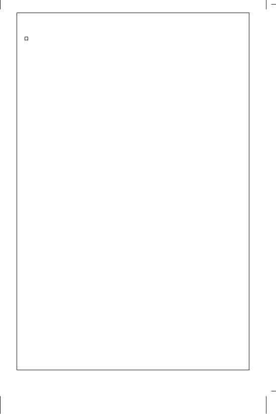
5. Route the Piping
Bath Spout as Primary Outlet
Install piping and elbows to the bath and showerhead installation locations. Use thread sealant on all threaded connections.
Secure the piping to the framing.
Solder all needed connections.
Temporarily install 1/2” pipe nipples to the elbows so they will extend at least 2” (51 mm) beyond the finished wall.
Install caps to both pipe nipples.
Proceed to the “Reassemble the Valve” section.
Kohler Co. |
11 |
1128093-2-E |

1/2" Pipe Nipple
Showerhead Outlet
Handshower Outlet
Cold Supply
1/2" Pipe Nipple
Hot Supply
6. Route the Piping
Showerhead as Primary Outlet
NOTE: Illustration shows the recommended piping configuration. Piping may need to be modified to accommodate your specific site.
Install piping and elbows to the showerhead and handshower supply locations. Use thread sealant on all threaded connections.
Secure the piping to the framing.
Solder all needed connections.
Temporarily install 1/2” pipe nipples to the elbows so they will extend at least 2” (51 mm) beyond the finished wall.
Install caps to both pipe nipples.
Proceed to the “Reassemble the Valve” section.
1128093-2-E |
12 |
Kohler Co. |
Cap Assembly
Pressure
Balancing Unit
Black Tab
Stop Assembly
Collar
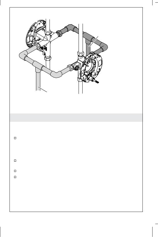
7. Reassemble the Valve
Solder Installations Only
Slowly open the water supply and flush the lines and valve body before assembling the internal components. Turn off the water supply.
Reinstall the stop assembly (certain models) and the pressure balancing unit.
For reversed valves in back-to-back installations proceed to ″Back-to-Back Installations Only.″
Reinstall the cap assembly with the black tab oriented up.
Install the collar and secure with the screws.
Back-to-Back Installations Only
The cap assembly for the reversed valve only will need to be reinstalled, with the black tab oriented down, to the valve with the reversed supply connections. Install the cap assembly to the second valve with the black tab oriented up.
Install the collar and secure with the screws.
Kohler Co. |
13 |
1128093-2-E |
Cap
8. Flush the System
Remove the cap from one of the pipe nipples.
Turn the valve stem clockwise to the full open position. Water will flow from the uncapped outlet.
Turn the valve stem counterclockwise to close.
Reinstall the cap.
Repeat for the second pipe nipple.
Reinstall the cap.
1128093-2-E |
14 |
Kohler Co. |
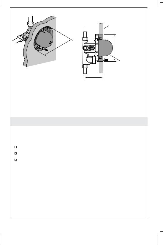
Finished Wall
Ø 5-9/16" |
Ø 5-9/16" |
(141 mm) |
|
(141 mm) |
|
|
Plaster Guard |
*2-3/4" (70 mm) – 3-1/2" (89 mm) Rough-In Depth
* Refer to the valve trim specification sheet for roughing-in dimensions.
9. Install the Finished Wall
Thick Wall
NOTE: The plaster guard can be used as a guide for marking the cutout.
Cut a 5-9/16″ (141 mm) hole in the wall material.
Install the finished wall material.
Leave the plaster guard in place at this time.
Kohler Co. |
15 |
1128093-2-E |

Plaster Guard |
|
Ø 3-1/2" |
||
|
(89 mm) |
|||
|
|
Plaster Guard |
||
Discard. |
2-3/4" (70 mm) |
|
|
|
Rough-In Depth |
|
|
||
|
|
|
||
1-9/16" |
|
|
|
|
(40 mm) |
45˚ |
Wall |
||
45˚ |
Material |
|||
|
|
|||
1-9/16" |
|
|
|
|
(40 mm) |
|
|
|
|
|
Screws |
|
Drywall |
|
Ø 4-1/2" |
Ø 4-1/2" |
|
Screws |
|
|
|
|||
(114 mm) |
(114 mm) |
|
|
|
10. Install the Finished Wall
Thin Wall
Twist the dome of the plaster guard to separate it from the outer ring. Discard the outer ring.
Slide the dome over the valve stem.
NOTE: The plaster guard dome can be used as a guide for marking the cutout.
Cut a 4″ (102 mm) hole in the wall material.
For Valves with Stops: Using the holes in the valve backing plate as a guide, cut openings for the stops.
Secure the wall material to the valve backing plate at the locations shown.
Leave the plaster guard dome in place at this time.
1128093-2-E |
16 |
Kohler Co. |

Black Tab |
Setscrew |
Collar |
O-Ring |
|
|
|
|
Minor |
Major |
|
Valve Stem |
||||
Adjustment |
Adjustment |
|||
|
|
|||
Temperature Limiting Adjustment
CAUTION: Risk of personal injury. If the water temperature is set too high, scalding will occur. The water temperature should never be set above 120°F (49°C).
Turn the valve stem clockwise to the full open position. Allow the water to run for several minutes.
Using a thermometer, check the water temperature.
Turn off the water.
Minor Temperature Adjustment
Using a hex wrench, turn the setscrew clockwise to lower the temperature and counterclockwise to raise the temperature.
Recheck the water temperature.
Major Temperature Adjustment
Remove the O-ring and collar from the valve stem.
Turn the valve stem clockwise in small increments. Check the water temperature at each increment.
Once the desired maximum water temperature is reached, leave the water running and reinstall the collar to the valve stem with the setscrew positioned against the black tab.
Turn off the water.
Reinstall the O-ring.
Kohler Co. |
17 |
1128093-2-E |

Warranty
KOHLER® Faucet Lifetime Limited Warranty
Kohler Co. warrants its Faucets* manufactured after January 1, 1997, to be leak and drip free during normal residential use for as long as the original consumer purchaser owns his or her home. If the Faucet should leak or drip during normal use, Kohler Co. will, free of charge, mail to the purchaser the cartridge necessary to put the Faucet in good working condition. This warranty applies only to Kohler Faucets installed in the United States of America, Canada or Mexico (″North America″).
Kohler Co. also warrants all other aspects of the faucet or accessories (″Faucet″)*, (except gold, non-Vibrant®, non-chrome finishes) to be free of defects in material and workmanship during normal residential use for as long as the original consumer purchaser owns his or her home. This warranty applies only to Kohler Faucets installed in North America. If a defect is found in normal residential use, Kohler Co. will, at its election, repair, provide a replacement part or product, or make appropriate adjustment. Damage to a product caused by accident, misuse, or abuse is not covered by this warranty. Improper care and cleaning will void the warranty**. Proof of purchase (original sales receipt) must be provided to Kohler Co. with all warranty claims. Kohler Co. is not responsible for labor charges, installation, or other incidental or consequential costs. In no event shall the liability of Kohler Co. exceed the purchase price of the Faucet.
If the Faucet is used commercially or is installed outside of North America, or if the finish is gold, non-Vibrant or a painted or powder coated color finish, Kohler Co. warrants the Faucet to be free from defects in material and workmanship for one (1) year from the date the product is installed, under Kohler Co.’s standard one-year limited warranty.
If you believe that you have a warranty claim, contact Kohler Co., either through your Dealer, Plumbing Contractor, Home Center or E-tailer, or by writing Kohler Co., Attn.: Customer Care Center, 444 Highland Drive, Kohler, WI 53044, USA. Please be sure to provide all pertinent information regarding your claim, including a complete description of the problem, the product, model number, color, finish, the date the product was purchased and from whom the product was purchased. Also include your original invoice. For other information, or to obtain the name and address of the service and repair facility nearest you, call 1-800-4-KOHLER (1-800-456-4537) from within the USA and Canada, and 001-800-456-4537 from within Mexico, or visit www.kohler.com within the USA, www.ca.kohler.com from within Canada, or www.mx.kohler.com in Mexico.
KOHLER CO. AND/OR SELLER ARE PROVIDING THESE
1128093-2-E |
18 |
Kohler Co. |
 Loading...