


KOHLER K-T10110, K-T10182, K-T10301, K-T10357, K-T10359 Installation Manual
...Installation Guide
Thermostatic Valve Trim
K-T10110, K-T10182, K-T10301,
K-T10357, K-T10359, K-T10421,
K-T10426, K-T10593, K-T10680,
K-T10940, K-T13173, K-T14488,
K-T16175, K-T16239, K-T18090
M product numbers are for Mexico (i.e. K-12345M) Los números de productos seguidos de
M corresponden a México (Ej. K-12345M)
Français, page ″Français-1″ Español, página ″Español-1″
1041503-2-H

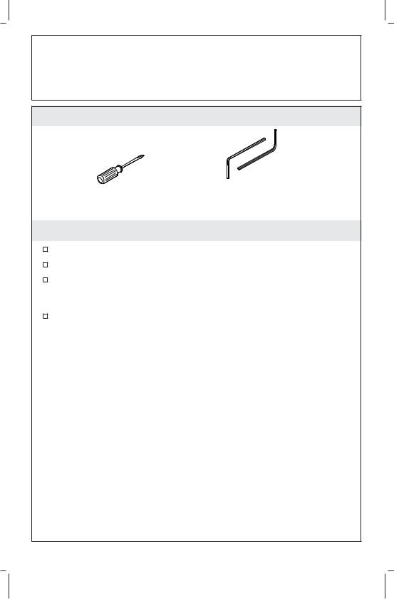
Tools and Materials
Screwdrivers |
Hex |
|
Wrenches |
Before You Begin
Shut off the main water supply.
Observe all local plumbing and building codes.
The trim design illustrated in this guide is representative and may differ from the actual trim being installed. Install the trim as instructed.
Kohler Co. reserves the right to make revisions in the design of products without notice, as specified in the price book.
1041503-2-H |
2 |
Kohler Co. |

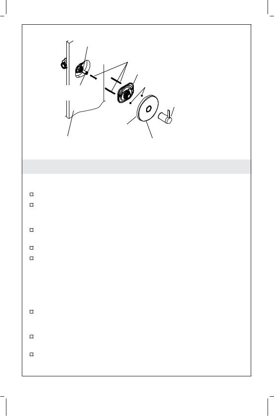
Remove and discard the plaster guard.
Select the correct |
Valve Stem |
valve stem adapter. |
Adapter |
Spline Adapter |
Finished Wall |
|
1. Install the Valve Stem Adapter
NOTE: Check the finished wall surface as related to the graphics on the plaster guard.
Select the correct length valve stem adapter and valve stem adapter screw for your application. Refer to the information stamped on the plaster guard to verify the wall thickness.
For a thin wall - 3/16″ (5 mm) to 9/16″ (1.4 cm): use the 7/8″ (2.2 cm) (short size) valve stem adapter, stamped ″3″ on the plaster guard, and the 1-3/8″ (3.5 cm) screw.
For a standard wall - 9/16″ (1.4 cm) to 1-1/16″ (2.7 cm): use the 1-3/8″ (3.5 cm) (middle size) valve stem adapter, stamped ″1″ on the plaster guard, and the 1-3/4″ (4.4 cm) screw.
For a thick wall - 1-1/16″ (2.7 cm) to 1-9/16″ (4 cm): use the 1-7/8″ (4.8 cm) (long size) valve stem adapter, stamped ″2″ on the plaster guard, and the 2-3/8″ (6 cm) screw.
Remove and discard the plaster guard from the thermostatic valve.
Place the spline adapter over the valve stem.
Set the correct valve stem adapter over the valve stem. Do not completely press or screw the valve stem adapter into place until instructed to do so.
Kohler Co. |
3 |
1041503-2-H |

Valve
Spline Adapter
Valve Stem
Adapter
Handle
Assembly
2. Adjust the Handle Assembly
Ensure the valve stem adapter is lightly placed over the spline adapter.
Place the handle assembly over the valve stem adapter.
Turn the handle assembly clockwise until the stop is contacted. The valve will be in the full cold position. The handle should be between the 9 and 10 o’clock positions.
Rotate the handle assembly counterclockwise, through the detent, then to the high temperature limit stop.
Verify that the handle assembly is between the 3 and 4 o’clock position.
Rotate back to 6 o’clock position.
Remove the handle assembly and set aside.
To adjust for handle alignment:
NOTE: The spline adapter allows fine adjustment of the handle alignment.
Remove the handle assembly and the valve stem adapter.
Reposition the spline adapter.
Reinstall the handle assembly and the valve stem adapter.
Check the alignment. Repeat this procedure until the handle alignment is satisfactory.
1041503-2-H |
4 |
Kohler Co. |
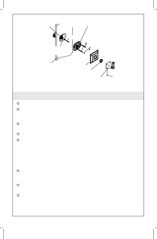
Thermostatic Valve
Screw
Front Plate Assembly
Nuts
Valve Stem
Adapter
Handle Assembly
Escutcheon
Finished Wall |
Drain Hole |
|
3. Install the Trim
NOTE: If you are installing the K-T10421 trim, proceed to the ″Install the Trim - K-T10421″ section of this guide.
Firmly press the valve stem adapter onto the valve stem.
Secure the valve stem adapter to the valve with the correct length screw, as selected in the ″Install the Valve Stem Adapter″ section of this guide.
Thread the two threaded studs into the threaded holes of the valve.
Place the front plate assembly over the threaded studs.
Thread the nuts onto the studs to secure the front plate assembly to the wall. Do not overtighten the nuts.
NOTE: If the front plate assembly does not lay flat on the wall surface, loosen the nuts and adjust the threaded studs, then tighten the nuts. The maximum distance between the threaded studs from the wall is 7/16″ (1.11 cm).
Visually inspect the front plate assembly to ensure that the foam seal is completely covering the wall opening. If not, stop the installation and repair the wall opening.
Place the escutcheon against the wall. The drain hole in the escutcheon should face downward in the 6 o’clock position.
Thread the handle assembly onto the hub of the front plate assembly to secure the escutcheon in place. The handle will be pointing down to the 6 o’clock position.
Kohler Co. |
5 |
1041503-2-H |

Install the Trim (cont.)
NOTE: If the handle does not engage the valve or the escutcheon does not tighten to the wall, replace the valve stem adapter with an adapter of appropriate length.
1041503-2-H |
6 |
Kohler Co. |
Thermostatic |
Front Plate Assembly |
|
|
|
|
Valve |
|
|
|
Screw |
|
|
Threaded Studs |
|
Valve Stem |
Nuts |
|
|
|
|
Adapter |
|
|
Finished |
Escutcheon |
|
Wall |
|
|
Adapter Ring |
|
|
|
|
|
|
Handle |
Setscrew |
|
Assembly |
|
4. Install the Trim - K-T10421
Firmly press the valve stem adapter onto the valve stem.
Secure the valve stem adapter to the valve stem with the correct length screw, as selected in the ″Install the Valve Stem Adapter″ section of this guide.
Thread the two threaded studs into the threaded holes of the valve.
Place the front plate assembly over the threaded studs.
Thread the nuts onto the studs to secure the front plate assembly to the wall. Do not overtighten the nuts.
NOTE: If the front plate assembly does not lay flat on the wall surface, loosen the nuts and adjust the threaded studs, then re-tighten the nuts. The maximum distance between the threaded studs from the wall is 7/16″ (1.1 cm).
Visually inspect the front seal plate assembly to ensure that the foam seal is completely covering the wall opening. If not, stop the installation and repair the wall opening.
Place the escutcheon against the wall. The drain hole in the escutcheon should face downward in the 6 o’clock position.
Thread the adapter ring onto the hub of the front plate assembly.
Kohler Co. |
7 |
1041503-2-H |
Install the Trim - K-T10421 (cont.)
Place the handle assembly against the escutcheon by lining up the pins in the handle assembly with the holes in the escutcheon. Make sure the handle is pointing down to the 6 o’clock position and the setscrew hole is facing down.
Tighten the setscrew in place with a hex wrench. Make sure the handle assembly is tight against the escutcheon.
1041503-2-H |
8 |
Kohler Co. |
Guide d’installation
Garniture de valve thermostatique
Outils et matériels
Tournevis |
Clés |
|
hexagonales |
Avant de commencer
Couper l’alimentation d’eau principale.
Respecter tous les codes de plomberie et de bâtiment locaux.
La conception de la garniture illustrée dans ce guide est représentative et pourrait différer de la garniture actuelle installée. Installer la garniture tel qu’instruit.
Kohler Co. se réserve le droit d’apporter toutes modifications sur le design des produits et ceci sans préavis, tel que spécifié dans le catalogue des prix.
Kohler Co. |
Français-1 |
1041503-2-H |
 Loading...