


Installation
Industrial/Commercial/Residential
Generator Sets
Models:
20-2800 kW
TP-5700 7/93d
California Proposition 65
WARNING
Engine exhaust from this product contains chemicals known to the State of California to cause cancer, birth defects, or other reproductive harm.
Product Identification Information
Product identification numbers determine service parts. Record the product identification numbers in the spaces below immediately after unpacking the products so that the numbers are readily available for future reference. Record field-installed kit numbers after installing the kits.
Generator Set Identification Numbers
Record the product identification numbers from the generator set nameplate(s).
Model Designation Specification Number Serial Number
Accessory Number Accessory Description
Engine Identification
Record the product identification information from the engine nameplate.
Manufacturer
Model Designation
Serial Number

|
|
Table of Contents |
Product Identification Information . . . . . . . . . . . . . . . . . . . . . . . . . . . . . . . . . . . . . . . . |
. . . . Inside front cover |
|
Safety Precautions and Instructions . . . . . . . . . . . . . . . . . . . . . . . . . . . . . . . . . . . . . . . |
. . . . . . . . . . . . . . . . . I |
|
Introduction . . . . . . . . . . . . . . . . . |
. . . . . . . . . . . . . . . . . . . . . . . . . . . . . . . . . . . . . . . . . . . . . |
. . . . . . . . . . . . . . . . . i |
Service Assistance . . . . . . . . . . . |
. . . . . . . . . . . . . . . . . . . . . . . . . . . . . . . . . . . . . . . . . . . . |
. . . . . . . . . . . . . . . . . i |
Section 1 General . . . . . . . . . . . . |
. . . . . . . . . . . . . . . . . . . . . . . . . . . . . . . . . . . . . . . . . . . . |
. . . . . . . . . . . . . . . . . 1 |
Section 2 Load and Transport . |
. . . . . . . . . . . . . . . . . . . . . . . . . . . . . . . . . . . . . . . . . . . . |
. . . . . . . . . . . . . . . . . 3 |
2.1 Lifting the Generator Set . . . . . . . . . . . . . . . . . . . . . . . . . . . . . . |
. . . . . . . . . . . . . . . . . 3 |
|
2.1.1 |
Weather Housing . . . . . . . . . . . . . . . . . . . . . . . . . . . . . |
. . . . . . . . . . . . . . . . . 5 |
2.1.2 |
Sound Shield . . . . . . . . . . . . . . . . . . . . . . . . . . . . . . . . |
. . . . . . . . . . . . . . . . . 5 |
2.1.3 |
Subbase Fuel Tank . . . . . . . . . . . . . . . . . . . . . . . . . . . |
. . . . . . . . . . . . . . . . . 5 |
2.2 Transporting the Generator Set . . . . . . . . . . . . . . . . . . . . . . . . |
. . . . . . . . . . . . . . . . . 5 |
|
Section 3 Location . . . . . . . . . . . . . . . . . . . . . . . . . . . . . . . . . . . . . . . . . . . . . . . . . . . . . . . . . . . . . . . . . . . . . . . . 7
3.1 Location Factors . . . . . . . . . . . . . . . . . . . . . . . . . . . . . . . . . . . . . . . . . . . . . . . . . . . . . . 7
3.2 Weight . . . . . . . . . . . . . . . . . . . . . . . . . . . . . . . . . . . . . . . . . . . . . . . . . . . . . . . . . . . . . . . 7
3.3 Mounting . . . . . . . . . . . . . . . . . . . . . . . . . . . . . . . . . . . . . . . . . . . . . . . . . . . . . . . . . . . . . 8
3.4 Vibration Isolation . . . . . . . . . . . . . . . . . . . . . . . . . . . . . . . . . . . . . . . . . . . . . . . . . . . . . 9
Section 4 Air Requirements . . . . . . . . . . . . . . . . . . . . . . . . . . . . . . . . . . . . . . . . . . . . . . . . . . . . . . . . . . . . . . . . 11
4.1 General . . . . . . . . . . . . . . . . . . . . . . . . . . . . . . . . . . . . . . . . . . . . . . . . . . . . . . . . . . . . . . 11
4.2 Air-Cooled Generators . . . . . . . . . . . . . . . . . . . . . . . . . . . . . . . . . . . . . . . . . . . . . . . . . 12
4.3 Forced Air . . . . . . . . . . . . . . . . . . . . . . . . . . . . . . . . . . . . . . . . . . . . . . . . . . . . . . . . . . . . 13
4.4 Air-Vac Cooling System . . . . . . . . . . . . . . . . . . . . . . . . . . . . . . . . . . . . . . . . . . . . . . . . 14
4.5 Air Vent . . . . . . . . . . . . . . . . . . . . . . . . . . . . . . . . . . . . . . . . . . . . . . . . . . . . . . . . . . . . . . 15
4.6 Liquid-Cooled Models . . . . . . . . . . . . . . . . . . . . . . . . . . . . . . . . . . . . . . . . . . . . . . . . . . 16
4.7 Unit-Mounted Radiator Cooling . . . . . . . . . . . . . . . . . . . . . . . . . . . . . . . . . . . . . . . . . . 16
4.8 Remote Radiator Cooling . . . . . . . . . . . . . . . . . . . . . . . . . . . . . . . . . . . . . . . . . . . . . . . 17
4.9 City Water Cooling . . . . . . . . . . . . . . . . . . . . . . . . . . . . . . . . . . . . . . . . . . . . . . . . . . . . 18
4.10 Cooling Tower . . . . . . . . . . . . . . . . . . . . . . . . . . . . . . . . . . . . . . . . . . . . . . . . . . . . . . . . 18
4.11 Block Heaters . . . . . . . . . . . . . . . . . . . . . . . . . . . . . . . . . . . . . . . . . . . . . . . . . . . . . . . . 20
4.12 Recommended Coolant . . . . . . . . . . . . . . . . . . . . . . . . . . . . . . . . . . . . . . . . . . . . . . . . 20
Section 5 Exhaust System . . . . . . . . . . . . . . . . . . . . . . . . . . . . . . . . . . . . . . . . . . . . . . . . . . . . . . . . . . . . . . . . . 21
5.1 Flexible Section . . . . . . . . . . . . . . . . . . . . . . . . . . . . . . . . . . . . . . . . . . . . . . . . . . . . . . . 22
5.2 Condensation Trap . . . . . . . . . . . . . . . . . . . . . . . . . . . . . . . . . . . . . . . . . . . . . . . . . . . . 22
5.3 Piping . . . . . . . . . . . . . . . . . . . . . . . . . . . . . . . . . . . . . . . . . . . . . . . . . . . . . . . . . . . . . . . 22
5.4 Double-Sleeve Thimbles . . . . . . . . . . . . . . . . . . . . . . . . . . . . . . . . . . . . . . . . . . . . . . . 23
Section 6 Fuel Systems . . . . . . . . . . . . . . . . . . . . . . . . . . . . . . . . . . . . . . . . . . . . . . . . . . . . . . . . . . . . . . . . . . . 25
6.1 Diesel Fuel Systems . . . . . . . . . . . . . . . . . . . . . . . . . . . . . . . . . . . . . . . . . . . . . . . . . . . 25 6.2 Main Fuel Tank . . . . . . . . . . . . . . . . . . . . . . . . . . . . . . . . . . . . . . . . . . . . . . . . . . . . . . . 26 6.3 Fuel Lines . . . . . . . . . . . . . . . . . . . . . . . . . . . . . . . . . . . . . . . . . . . . . . . . . . . . . . . . . . . . 27 6.4 Transfer Tanks . . . . . . . . . . . . . . . . . . . . . . . . . . . . . . . . . . . . . . . . . . . . . . . . . . . . . . . . 27 6.5 Auxiliary Fuel Pumps . . . . . . . . . . . . . . . . . . . . . . . . . . . . . . . . . . . . . . . . . . . . . . . . . . 28 6.6 Gasoline Fuel Systems . . . . . . . . . . . . . . . . . . . . . . . . . . . . . . . . . . . . . . . . . . . . . . . . 29 6.7 Natural or LP Gas Fuel Systems . . . . . . . . . . . . . . . . . . . . . . . . . . . . . . . . . . . . . . . . 30 6.8 Flexible Connector . . . . . . . . . . . . . . . . . . . . . . . . . . . . . . . . . . . . . . . . . . . . . . . . . . . . 32 6.9 Gas Piping . . . . . . . . . . . . . . . . . . . . . . . . . . . . . . . . . . . . . . . . . . . . . . . . . . . . . . . . . . . 32 6.10 Fuel Regulators . . . . . . . . . . . . . . . . . . . . . . . . . . . . . . . . . . . . . . . . . . . . . . . . . . . . . . . 32 6.11 LP Gas Fuel Characteristics . . . . . . . . . . . . . . . . . . . . . . . . . . . . . . . . . . . . . . . . . . . . 33 6.12 Vapor Withdrawal Systems . . . . . . . . . . . . . . . . . . . . . . . . . . . . . . . . . . . . . . . . . . . . . 33 6.13 Liquid Withdrawal Systems . . . . . . . . . . . . . . . . . . . . . . . . . . . . . . . . . . . . . . . . . . . . . 33 6.14 Dual Systems (Natural and LP Gas) . . . . . . . . . . . . . . . . . . . . . . . . . . . . . . . . . . . . . 33 6.15 Natural Gas . . . . . . . . . . . . . . . . . . . . . . . . . . . . . . . . . . . . . . . . . . . . . . . . . . . . . . . . . . 34 6.16 Combination Gas-Gasoline . . . . . . . . . . . . . . . . . . . . . . . . . . . . . . . . . . . . . . . . . . . . . 34
TP-5700 7/93 |
Table of Contents |

Table of Contents, continued
Section 7 Electrical Requirements . . . . . . . . . . . . . . . . . . . . . . . . . . . . . . . . . . . . . . . . . . . . . . . . . . . . . . . . . . 35
7.1 Batteries . . . . . . . . . . . . . . . . . . . . . . . . . . . . . . . . . . . . . . . . . . . . . . . . . . . . . . . . . . . . . 35
7.2 Electrical Connections . . . . . . . . . . . . . . . . . . . . . . . . . . . . . . . . . . . . . . . . . . . . . . . . . 36
7.3 Load Lead Connections . . . . . . . . . . . . . . . . . . . . . . . . . . . . . . . . . . . . . . . . . . . . . . . . 36
7.4 Terminal Connector Torque . . . . . . . . . . . . . . . . . . . . . . . . . . . . . . . . . . . . . . . . . . . . . 37
7.5 Automatic Transfer Switches . . . . . . . . . . . . . . . . . . . . . . . . . . . . . . . . . . . . . . . . . . . . 38
7.6 Control Connections . . . . . . . . . . . . . . . . . . . . . . . . . . . . . . . . . . . . . . . . . . . . . . . . . . . 38
7.7 Remote Annunciator . . . . . . . . . . . . . . . . . . . . . . . . . . . . . . . . . . . . . . . . . . . . . . . . . . . 38
7.8 Audiovisual Alarm . . . . . . . . . . . . . . . . . . . . . . . . . . . . . . . . . . . . . . . . . . . . . . . . . . . . . 38
7.9 Remote Emergency Stop Switch . . . . . . . . . . . . . . . . . . . . . . . . . . . . . . . . . . . . . . . . 39
7.10 Dry Contact Kit . . . . . . . . . . . . . . . . . . . . . . . . . . . . . . . . . . . . . . . . . . . . . . . . . . . . . . . 39
7.11 Wiring . . . . . . . . . . . . . . . . . . . . . . . . . . . . . . . . . . . . . . . . . . . . . . . . . . . . . . . . . . . . . . . 39
Appendix A Abbreviations . . . . . . . . . . . . . . . . . . . . . . . . . . . . . . . . . . . . . . . . . . . . . . . . . . . . . . . . . . . . . . . . A-1
Table of Contents |
TP-5700 7/93 |
Safety Precautions and Instructions
IMPORTANT SAFETY INSTRUCTIONS. Electromechanical equipment, including generator sets, transfer switches, switchgear, and accessories, can cause bodily harm and pose life-threatening danger when improperly installed, operated, or maintained. To prevent accidents be aware of potential dangers and act safely. Read and follow all safety precautions and instructions. SAVE THESE INSTRUCTIONS.
This manual has several types of safety precautions and instructions: Danger, Warning, Caution, and Notice.
DANGER
Danger indicates the presence of a hazard that will cause severe personal injury, death, or substantial property damage.
WARNING
Warning indicates the presence of a hazard that can cause severe personal injury, death, or substantial property damage.
CAUTION
Caution indicates the presence of a hazard that will or can cause minor personal injury or property damage.
NOTE
Notice communicates installation, operation, or maintenance information that is safety related but not hazard related.
Safety decals affixed to the equipment in prominent places alert the operator or service technician to potential hazards and explain how to act safely. The decals are shown throughout this publication to improve operator recognition. Replace missing or damaged decals.
Accidental Starting
WARNING
Accidental starting.
Can cause severe injury or death.
Disconnect the battery cables before working on the generator set. Remove the negative (--) lead first when disconnecting the battery. Reconnect the negative (--) lead last when reconnecting the battery.
Disabling the generator set. Accidental starting can cause severe injury or death. Before working on the generator set or connected equipment, disable the generator set as follows: (1) Move the generator set master switch to the OFF position. (2) Disconnect the power to the battery charger. (3) Remove the battery cables, negative (--) lead first. Reconnect the negative (--) lead last when reconnecting the battery. Follow these precautions to prevent starting of the generator set by an automatic transfer switch, remote start/stop switch, or engine start command from a remote computer.
Battery
WARNING
Sulfuric acid in batteries.
Can cause severe injury or death.
Wear protective goggles and clothing. Battery acid may cause blindness and burn skin.
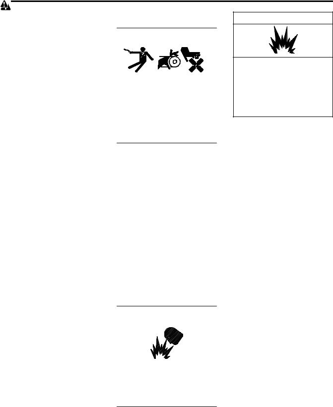
WARNING
Explosion.
Can cause severe injury or death. Relays in the battery charger cause arcs or sparks.
Locate the battery in a well-ventilated area. Isolate the battery charger from explosive fumes.
Battery gases. Explosion can cause severe injury or death. Battery gases can cause an explosion. Do not smoke or permit flames or sparks to occur near a battery at any time, particularly when it is charging. Do not dispose of a battery in a fire. To prevent burns and sparks that could cause an explosion, avoid touching the battery terminals with tools or other metal objects. Remove wristwatch, rings, and other jewelry before servicing the equipment. Discharge static electricity from your body before touching batteries by first touching a grounded metal surface away from the battery. To avoid sparks, do not disturb the battery charger connections while the battery is charging. Always turn the battery charger off before disconnecting the battery connections. Ventilate the compartments containing batteries to prevent accumulation of explosive gases.
Battery electrolyte is a diluted sulfuric acid. Battery acid can cause severe injury or death. Battery acid can cause blindness and burn skin. Always wear splashproof safety goggles, rubber gloves, and boots when servicing the battery. Do not open a sealed battery or mutilate the battery case. If battery acid splashes in the eyes or on the skin, immediately flush the affected area for 15 minutes with large quantities of clean water. Seek immediate medical aid in the case of eye contact. Never add acid to a battery after placing the battery in service, as this may result in hazardous spattering of battery acid.
TP-5700 7/93 |
Safety Precautions and Instructions |
I |
Battery short circuits. Explosion can cause severe injury or death.
Short circuits can cause bodily injury and/or equipment damage. Disconnect the battery before generator set installation or maintenance. Remove wristwatch, rings, and other jewelry before servicing the equipment. Use tools with insulated handles. Remove the negative (--) lead first when disconnecting the battery. Reconnect the negative (--) lead last when reconnecting the battery. Never connect the negative (--) battery cable to the positive (+) connection terminal of the starter solenoid. Do not test the battery condition by shorting the terminals together.
Battery acid cleanup. Battery acid can cause severe injury or death.
Battery acid is electrically conductive and corrosive. Add 500 g (1 lb.) of bicarbonate of soda (baking soda) to a container with 4 L (1 gal.) of water and mix the neutralizing solution. Pour the neutralizing solution on the spilled battery acid and continue to add the neutralizing solution to the spilled battery acid until all evidence of a chemical reaction (foaming) has ceased. Flush the resulting liquid with water and dry the area.
Engine Backfire/Flash
Fire
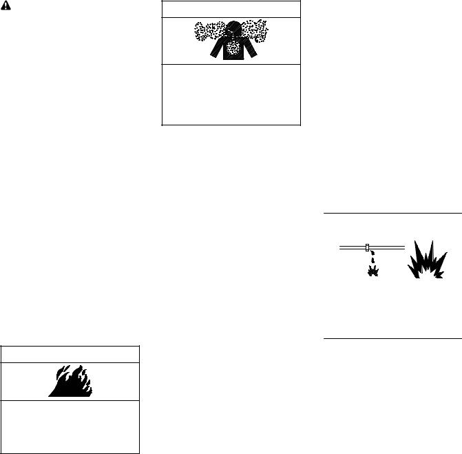
WARNING
Fire.
Can cause severe injury or death.
Do not smoke or permit flames or sparks near fuels or the fuel system.
Servicing the fuel system. A flash fire can cause severe injury or death.
Do not smoke or permit flames or sparks near the carburetor, fuel line, fuel filter, fuel pump, or other potential sources of spilled fuels or fuel vapors. Catch fuels in an approved container when removing the fuel line or carburetor.
Servicing the air cleaner. A sudden backfire can cause severe injury or death. Do not operate the generator set with the air cleaner removed.
Exhaust System
WARNING
Carbon monoxide.
Can cause severe nausea, fainting, or death.
The exhaust system must be leakproof and routinely inspected.
Copper tubing exhaust systems. Carbon monoxide can cause severe nausea, fainting, or death. Do not use copper tubing in diesel exhaust systems. Sulfur in diesel exhaust causes rapid deterioration of copper tubing exhaust systems, resulting in exhaust leakage.
Generator set operation. Carbon monoxide can cause severe nausea, fainting, or death. Carbon monoxide is an odorless, colorless, tasteless, nonirritating gas that can cause death if inhaled for even a short time. Avoid breathing exhaust fumes when working on or near the generator set. Never operate the generator set inside a building unless the exhaust gas is piped safely outside. Never operate the generator set where exhaust gas could accumulate and seep back inside a potentially occupied building.
Carbon monoxide symptoms. Carbon monoxide can cause severe nausea, fainting, or death. Carbon monoxide is a poisonous gas present in exhaust gases. Carbon monoxide poisoning symptoms include but are not limited to the following:
DLight-headedness, dizziness
DPhysical fatigue, weakness in joints and muscles
DSleepiness, mental fatigue, inability to concentrate
or speak clearly, blurred vision
DStomachache, vomiting, nausea If experiencing any of these symptoms and carbon monoxide poisoning is possible, seek fresh air immediately and remain active. Do not sit, lie down, or fall asleep. Alert others to the possibility of carbon monoxide poisoning. Seek medical attention if the condition of affected persons does not improve within minutes of breathing fresh air.
Fuel System
WARNING
Explosive fuel vapors.
Can cause severe injury or death.
Use extreme care when handling, storing, and using fuels.
Draining the fuel system. Explosive fuel vapors can cause severe injury or death. Spilled fuel can cause an explosion. Use a container to catch fuel when draining the fuel system. Wipe up spilled fuel after draining the system.
LP liquid withdrawal fuel leaks. Explosive fuel vapors can cause severe injury or death. Fuel leakage can cause an explosion. Check the LP liquid withdrawal gas fuel system for leakage by using a soap and water solution with the fuel system test pressurized to at least 90 psi (621 kPa). Do not use a soap solution containing either ammonia or chlorine because both prevent bubble formation. A successful test depends on the ability of the solution to bubble.
II |
Safety Precautions and Instructions |
TP-5700 7/93 |
The fuel system. Explosive fuel vapors can cause severe injury or death. Vaporized fuels are highly explosive. Use extreme care when handling and storing fuels. Store fuels in a well-ventilated area away from spark-producing equipment and out of the reach of children. Never add fuel to the tank while the engine is running because spilled fuel may ignite on contact with hot parts or from sparks. Do not smoke or permit flames or sparks to occur near sources of spilled fuel or fuel vapors. Keep the fuel lines and connections tight and in good condition. Do not replace flexible fuel lines with rigid lines. Use flexible sections to avoid fuel line breakage caused by vibration. Do not operate the generator set in the presence of fuel leaks, fuel accumulation, or sparks. Repair fuel systems before resuming generator set operation.
Explosive fuel vapors can cause severe injury or death. Take additional precautions when using the following fuels:
Gasoline—Store gasoline only in approved red containers clearly marked GASOLINE.
Propane (LP)—Adequate ventilation is mandatory. Because propane is heavier than air, install propane gas detectors low in a room. Inspect the detectors per the manufacturer’s instructions.
Natural Gas—Adequate ventilation is mandatory. Because natural gas rises, install natural gas detectors high in a room. Inspect the detectors per the manufacturer’s instructions.
Fuel tanks. Explosive fuel vapors can cause severe injury or death.
Gasoline and other volatile fuels stored in day tanks or subbase fuel tanks can cause an explosion. Store only diesel fuel in tanks.
Gas fuel leaks. Explosive fuel vapors can cause severe injury or death. Fuel leakage can cause an explosion. Check the LP vapor gas or natural gas fuel system for leakage by using a soap and water solution with the fuel system test pressurized to 6--8 ounces per square inch (10--14 inches water column). Do not use a soap solution containing either ammonia or chlorine because both prevent bubble formation. Asuccessful test depends on the ability of the solution to bubble.
Hazardous Noise
CAUTION
Hazardous noise.
Can cause hearing loss.
Never operate the generator set without a muffler or with a faulty exhaust system.
Hazardous Voltage/
Electrical Shock
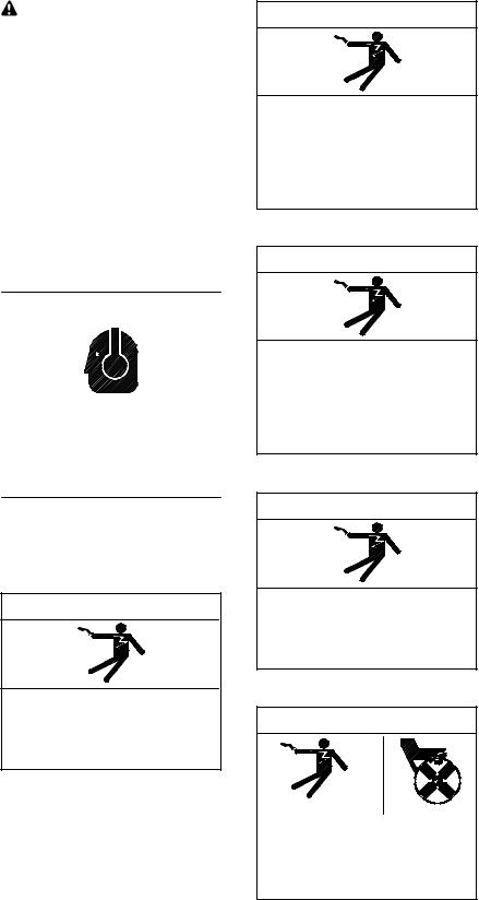
DANGER
Hazardous voltage.
Will cause severe injury or death.
Disconnect all power sources before opening the enclosure.
(over 600 volts)
DANGER
Hazardous voltage.
Will cause severe injury or death.
Disconnect all power sources before servicing. Install the barrier after adjustments, maintenance, or servicing.
(over 600 volts)
WARNING
Hazardous voltage.
Can cause severe injury or death.
Disconnect all power sources before servicing. Install the barrier after adjustments, maintenance, or servicing.
(600 volts and under)
WARNING
Hazardous voltage.
Can cause severe injury or death.
Disconnect all power sources before opening the enclosure.
(600 volts and under)
WARNING
Hazardous voltage. Moving rotor. Can cause severe injury or death.
Operate the generator set only when all guards and electrical enclosures are in place.
TP-5700 7/93 |
Safety Precautions and Instructions III |
WARNING
Hazardous voltage.
Backfeed to the utility system can cause property damage, severe injury, or death.
If the generator set is used for standby power, install an automatic transfer switch to prevent inadvertent interconnection of standby and normal sources of supply.
Grounding electrical equipment. Hazardous voltage can cause severe injury or death. Electrocution is possible whenever electricity is present. Open the main circuit breakers of all power sources before servicing the equipment. Configure the installation to electrically ground the generator set, transfer switch, and related equipment and electrical circuits to comply with applicable codes and standards. Never contact electrical leads or appliances when standing in water or on wet ground because these conditions increase the risk of electrocution.
Installing the battery charger. Hazardous voltage can cause severe injury or death. An ungrounded battery charger may cause electrical shock. Connect the battery charger enclosure to theground of a permanent wiring system. As an alternative, install an equipment grounding conductor with circuit conductors and connect it to the equipment grounding terminal or the lead on the battery charger. Install the battery charger as prescribed in the equipment manual. Install the battery charger in compliance with local codes and ordinances.
Connecting the battery and the battery charger. Hazardous voltage can cause severe injury or death.
Reconnect the battery correctly, positive to positive and negative to negative, to avoid electrical shock and damage to the battery charger and battery(ies). Have a qualified electrician install the battery(ies).
Servicing the day tank. Hazardous voltage can cause severe injury or death. Service the day tank electrical control module (ECM) as prescribed in the equipment manual. Disconnect the power to the day tank before servicing. Press the day tank ECM OFF pushbutton to disconnect the power. Notice that line voltage is still present within the ECM when the POWER ON light is lit. Ensure that the generator set and day tank are electrically grounded. Do not operate the day tank when standing in water or on wet ground because these conditions increase the risk of electrocution.
Short circuits. Hazardous voltage/current can cause severe injury or death. Short circuits can cause bodily injury and/or equipment damage. Do not contact electrical connections with tools or jewelry while making adjustments or repairs. Remove wristwatch, rings, and jewelry before servicing the equipment.
Engine block heater. Hazardous voltage can cause severe injury or death. The engine block heater can cause electrical shock. Remove the engine block heater plug from the electrical outlet before working on the block heater electrical connections.
Electrical backfeed to the utility. Hazardous backfeed voltage can cause severe injury or death. Install a transfer switch in standby power installations to prevent the connection of standby and other sources of power. Electrical backfeed into a utility electrical system can cause serious injury or death to utility personnel working on power lines.
Installing accessories to the transformer assembly. Hazardous voltage can cause severe injury or death. To prevent electrical shock disconnect the harness plug before installing accessories that will be connected to transformer assembly primary terminals 76, 77, 78, and 79. Terminals are at line voltage. (Models with E33+, S340, S340+, 340, R340, and R33 controls only)
Installing accessories to the transformer assembly. Hazardous voltage can cause severe injury or death. To prevent electrical shock disconnect the harness plug before installing accessories that will be connected to the transformer assembly primary terminals on microprocessor logic models. Terminals are at line voltage.
Making line or auxiliary connections. Hazardous voltage can cause severe injury or death. To prevent electrical shock deenergizethe normal power source before making any line or auxiliary connections.
Servicing the transfer switch. Hazardous voltage can cause severe injury or death. Deenergize all power sources before servicing. Open the main circuit breakers of all transfer switch power sources and disable all generator sets as follows: (1) Move all generator set master controller switches to the OFF position. (2) Disconnect power to all battery chargers. (3) Disconnect all battery cables, negative (--) leads first. Reconnect negative (--) leads lastwhen reconnecting the battery cables after servicing. Follow these precautions to prevent the starting of generator sets by an automatic transfer switch, remote start/stop switch, or engine start command from a remote computer. Before servicing any components inside the enclosure: (1) Remove rings, wristwatch, and jewelry. (2) Stand on a dry, approved electrically insulated mat. (3) Test circuits with a voltmeter to verify that they are deenergized.
IV Safety Precautions and Instructions |
TP-5700 7/93 |
Servicing the transfer switch controls and accessories within the enclosure. Hazardous voltage can cause severe injury or death.
Disconnect the transfer switch controls at the inline connector to deenergize the circuit boards and logic circuitry but allow the transfer switch to continue to supply power to the load. Disconnect all power sources to accessories that are mounted within the enclosure but are not wired through the controls and deenergized by inline connector separation. Test circuits with a voltmeter to verify that they are deenergized before servicing.
Heavy Equipment
WARNING
Unbalanced weight.
Improper lifting can cause severe injury or death and equipment damage.
Do not use lifting eyes.
Lift the generator set using lifting bars inserted through the lifting holes on the skid.
WARNING
Unbalanced weight.
Improper lifting can cause severe injury or death and equipment damage.
Use adequate lifting capacity. Never leave the transfer switch standing upright unless it is securely bolted in place or stabilized.
Hot Parts
WARNING
Hot coolant and steam.
Can cause severe injury or death.
Before removing the pressure cap, stop the generator set and allow it to cool. Then loosen the pressure cap to relieve pressure.
WARNING
Hot engine and exhaust system. Can cause severe injury or death.
Do not work on the generator set until it cools.
Servicing the exhaust system. Hot parts can cause severe injury or death. Do not touch hot engine parts. The engine and exhaust system components become extremely hot during operation.
Checking the coolant level. Hot coolant can cause severe injury or death. Allow the engine to cool. Release pressure from the cooling system before removing the pressure cap. To release pressure, cover the pressure cap with a thick cloth and then slowly turn the cap counterclockwise to the first stop. Remove the cap after pressure has been completely released and the engine has cooled. Check the coolant level at the tank if the generator set has a coolant recovery tank.
Moving Parts
WARNING
Hazardous voltage. Moving rotor. Can cause severe injury or death.
Operate the generator set only when all guards and electrical enclosures are in place.
WARNING
Rotating parts.
Can cause severe injury or death.
Operate the generator set only when all guards, screens, and covers are in place.
Servicing the generator set when it is operating. Exposed moving parts can cause severe injury or death.
Keep hands, feet, hair, clothing, and test leads away from the belts and pulleys when the generator set is running. Replace guards, screens, and covers before operating the generator set.
TP-5700 7/93 |
Safety Precautions and Instructions V |
Notice
NOTICE
This generator set has been rewired from its nameplate voltage to
246242
NOTICE
Voltage reconnection. Affix a notice to the generator set after reconnecting the set to a voltage different from the voltage on the nameplate. Order voltage reconnection decal 246242 from an authorized service distributor/dealer.
NOTICE
Hardware damage. The engine and generator set may use both American Standard and metric hardware. Use the correct size tools to prevent rounding of the bolt heads and nuts.
NOTICE
Hardware damage. The transfer switch may use both American Standard and metric hardware. Use the correct size tools to prevent rounding of the bolt heads and nuts.
NOTICE
When replacing hardware, do not substitute with inferior grade hardware. Screws and nuts are available in different hardness ratings. To indicate hardness, American Standard hardware uses a series of markings, and metric hardware uses a numeric system. Check the markings on the bolt heads and nuts for identification.
NOTICE
Canadian installations only. For standby service connect the output of the generator set to a suitably rated transfer switch in accordance with Canadian Electrical Code, Part 1.
VI Safety Precautions and Instructions |
TP-5700 7/93 |
Introduction
This manual provides installation instructions for 20--2800 kW generator sets. Operation manuals and wiring diagram manuals are available separately.
x:in:001:001
Information in this publication represents data available at the time of print. Kohler Co. reserves the right to change this publication and the products represented without notice and without any obligation or liability whatsoever.
Read this manual and carefully follow all procedures and safety precautions to ensure proper equipment operation and to avoid bodily injury. Read and follow the Safety Precautions and Instructions section at the beginning of this manual. Keep this manual with the equipment for future reference.
x:in:001:002:a
Service Assistance
For professional advice on generator power requirements and conscientious service, please contact your nearest Kohler distributor or dealer.
DConsult the Yellow Pages under the heading Generators—Electric
DVisit the Kohler Power Systems website at KohlerPowerSystems.com
DLook at the labels and stickers on your Kohler product or review the appropriate literature or documents included with the product
DCall toll free in the US and Canada 1-800-544-2444
DOutside the US and Canada, call the nearest regional office
Africa, Europe, Middle East
London Regional Office
Langley, Slough, England
Phone: (44) 1753-580-771
Fax: (44) 1753-580-036
Asia Pacific
Power Systems Asia Pacific Regional Office
Singapore, Republic of Singapore
Phone: (65) 264-6422
Fax: (65) 264-6455
China
North China Regional Office, Beijing
Phone: (86) 10 6518 7950
(86) 10 6518 7951
(86) 10 6518 7952
Fax: (86) 10 6518 7955
East China Regional Office, Shanghai
Phone: (86) 21 6288 0500
Fax: (86) 21 6288 0550
India, Bangladesh, Sri Lanka
India Regional Office
Bangalore, India
Phone: (91) 80 3366208
(91) 80 3366231
Fax: (91) 80 3315972
Japan, Korea
North Asia Regional Office
Tokyo, Japan
Phone: (813) 3440-4515
Fax: (813) 3440-2727
Latin America
Latin America Regional Office
Lakeland, Florida, USA
Phone: (863) 619-7568
Fax: (863) 701-7131
X:in:008:001a
TP-5700 7/93 |
Introduction |
i |

Section 1 General
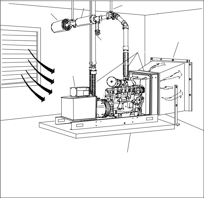
Industrial power systems give years of dependable service if installed using the guidelines provided in this manual and in applicable codes. Incorrect installation can cause continuing problems. Figure 1-1 illustrates a typical installation.
Your authorized generator set distributor/dealer may also provide advice about or assistance with your installation.
This manual references several organizations and their codes that provide installation requirements and guidelines such as the National Fire Protection Association (NFPA) and Underwriter’s Laboratories Inc. (UL).
DNFPA 54 National Fuel Gas Code
DNFPA 70 National Electrical Coder; the National Electrical Code is a registered trademark of the NFPA
DNFPA 99 Standard for Health Care Facilities
DNFPA 101 Life Safety Code
DNFPA 110 Emergency and Standby Power Systems
DUL-486A The Standard for Wire Connectors and Soldering Lugs for Use with Copper Conductors
DUL-486B The Standard for Wire Connectors for Use with Aluminum Conductors
DUL-486E Equipment Wiring Terminals for Use with Aluminum and/or Copper Conductors
DUL-2200 Stationary Engine Generator Assemblies
These organizations provide information specifically for US installations. Installers must comply with their respective national and local codes.
TP-5700 7/93 |
Section 1 General |
1 |
1
 10
10
1.Exhaust thimble (for wall or ceiling)
2.Silencer
3.Supports
4.Flexible sections
5.Duct work for cooling air outlet
2 |
3 |
9 |
5 |
|
|
|
4 |
8 
7
6
TP-5700-1
6.Mounting base
7.Controller
8.Electrical conduit
9.Water trap with drain
10.Fresh air intake
Figure 1-1 Typical Stationary-Duty Generator Set Installation
2 |
Section 1 General |
TP-5700 7/93 |

Section 2 Load and Transport
To ensure personal safety while preventing damage to the product, we strongly recommend the following guidelines be observed when loading and transporting standby generator sets. Due to the different designs, dimensions and weights of the generators involved, specific instructions for each model are not provided. However, these guidelines are applicable to the full standby line (although minor procedural changes may be necessary between sets). It is the responsibility of the dealer/distributor to see that generator loading and transport be performed within the framework of these guidelines. Obviously, prepackaged (crated) sets may be exempt from certain aspects of this section. (Prepackaged generators generally are loaded in their containers with the aid of lift trucks.)
2.1 Lifting the Generator Set
DDo not lift the generator set by the lifting eyes attached to the engine and/or alternator. These lifting eyes are only used during generator assembly and are not capable of supporting the entire weight of the generator. The mounting skid of each standby generator set includes four holes for attaching the lifting device. These holes are strategically placed to avoid damage to generator components by lifting cables and to maintain balance during lifting. In some cases, it may be necessary to remove protruding generator components (air cleaner, shrouding) to avoid damage by lifting cables.
TP-5700 7/93 |
Section 2 Load and Transport |
3 |

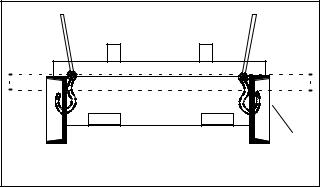
DA four-point lifting method is necessary to lift the generator set. To maintain generator balance during lifting, the lifting apparatus must utilize the four skid lifting holes mentioned in the previous paragraph. One method of lifting standby generators uses an apparatus of hooks and cables joined at a single rigging point. See Figure 2-2. The use of spreader bars is necessary with this method to avoid damage to the set during the lifting procedure. The spreader bars should be slightly wider than the generator skid so the set is not damaged by lifting cables and only vertical force is applied to the skid while lifting. The generators may also be lifted by placing bars through the skid lifting holes and attaching hooks to the ends of the bars. See Figure 2-1. Be sure the bars are properly sized for the weight of the generator set. Precautions must be taken to prevent the lifting hooks from sliding off the ends of the bars. Spreader bars may be necessary with this arrangement if lifting cables are in contact with the set. A specially designed lifting fixture is often used to lift the larger standby generators. The fixture usually includes adjustable cables to adapt to different size generators and to compensate for unit imbalance. See Figure 2-3. In all cases, be sure the components of the lifting device (cables, chains, bars) are properly sized for the weight of the generator set.
1
2
TP-5700-2
1.Spreader bars may be necessary to protect generator set
2.Lifting bars
Figure 2-1 Generator Set with Lifting Bars in Skid
1 |
TP-5700-2 |
1. Spreader bars may be necessary to protect generator set |
Figure 2-2 Generator Set with Lifting Hooks in Skid
1
1
TP-5700-2
1. Lifting fixture
Figure 2-3 Generator Set with Lifting Fixture
4 |
Section 2 Load and Transport |
TP-5700 7/93 |
DDo not attach lifting hooks to outside reinforcing plate on skid. Attach lifting hooks to skid exactly as shown in Figure 2-4. This method utilizes the strongest portion of the mounting skid and also prevents the lifting hooks from slipping. Generators without skid reinforcing plates can be raised with lift hooks on the inside or outside of the skid.
The following information pertains to lifting a generator set with subbase fuel tank, weather housing, and/or sound shield.
1 |
TP-5700-2 |
1. Reinforcing plate |
Figure 2-4 Lifting Hook Placement (above 1000 kW)
2.1.1Weather Housing
Lift the weather housing and generator set together as one unit using the generator set guidelines.
2.1.2Sound Shield
If the generator set has an installed sound shield and subbase fuel tank the assembly can be lifted as one unit provided the subbase fuel tank has lifting eyes installed and meets the criteria of subbase fuel tank paragraph 2. In all other cases, remove the sound shield per the following paragraphs.
Remove the sound shield, if installed, from the generator set before lifting the generator set. The sound shield attaching bolts may be hidden by the sound shield insulation. To locate the hardware carefully lift the sound insulation near the skid.
Remove the wood skid before lifting the sound shield using the eye bolts. Use the sound shield eye bolts, if equipped, to lift only the sound shield.
Reinstall the sound shield after lifting and mounting the generator set.
2.1.3Subbase Fuel Tank
The lifting contractor determines the type and suitability of the subbase fuel tank lifting device. Lift the subbase fuel tank as one unit if shipped separately from the generator set. Use lifting eyes if equipped on subbase fuel tank; otherwise, use chains or cables to lift the subbase fuel tank. If using lifting straps, protect the strap from sharp fuel tank edges.
Lift the generator set (up to 400 kW) and subbase fuel tank together provided the fuel tank is empty and the subbase fuel tank does not extend beyond the perimeter of the generator set skid.
In all other cases, remove the mounting hardware and wiring between the the generator set and subbase fuel tank. Lift the generator set and subbase fuel tank separately. It is not necessary to drain fuel tank when lifting just the fuel tank.
2.2 Transporting the Generator Set
DThe transporting vehicle/trailer must be sized for the dimension and weight of the generator set.
Consult the set dimensional drawing or contact the factory for information (weight, dimensions) pertinent to planning transport. The overall height of a generator set in transit (including vehicle/trailer) must not exceed 13.5 ft. (4.1 m) unless special hauling permits are obtained (check Federal, State, and local laws prior to transporting). Larger units (above 1000 kW) should be transported on low-boy-type trailers with a deck height of 25 in. (635 mm) or less to meet clearance requirements. Large (unboxed) generators with radiators should be loaded with the radiator facing the rear to reduce wind resistance while in transit. Radiators with free-wheeling fans must have the fan secured to prevent rotation that might introduce flying objects to the radiator core or fan blades.
DBe sure the generator set is securely fastened to the vehicle/trailer and covered with a tarpaulin.
Even the heaviest of units is capable of movement during shipment unless properly secured. Fasten the set to the vehicle/trailer bed with properly sized chain routed through the mounting holes of the skid. Use chain tighteners to remove slack from the mounting chain. Cover the entire unit with a heavy-duty tarpaulin and secure tarpaulin to the generator or trailer.
TP-5700 7/93 |
Section 2 Load and Transport |
5 |
 Loading...