


KOHLER K-475, K-476, K-477, K-478, K-480 Installation Manual
...Installation Guide
Accessories
K-475, K-476, K-477,
K-478, K-480, K-482,
K-485, K-486, K-487,
K-490, K-492
M product numbers are for Mexico (i.e. K-12345M) Los números de productos seguidos de
M corresponden a México (Ej. K-12345M)
Français, page ªFrançais-1º Español, página ªEspañol-1º
1020823-2-A

Tools and Materials
Thank You For Choosing Kohler Company
We appreciate your commitment to Kohler quality. Please take a few minutes to review this manual before you start installation. If you encounter any installation or performance problems, please don't hesitate to contact us. Our phone numbers and web site are listed on the back cover. Thanks again for choosing Kohler Company.
Before You Begin
DANGER: Risk of personal injury. These products are not designed or intended for use as a grab bar or support bar. Do not install any of these products in any area where they are likely to be used inadvertently as a grab bar or support bar.
These products should be located and mounted to a wall stud. While it is possible to mount them to any surface, a stud mounted product will yield the best results.
Use a level to ensure that the center lines for the wall plates are vertical where applicable and the post center lines are horizontal where applicable.
Kohler Co. reserves the right to make revisions in the design of products without notice, as speci®ed in the Price Book.
Observe all local plumbing codes and building codes.
1020823-2-A |
2 |
Kohler Co. |

1. Roughing-In Information |
|
|
Kohler Co. |
3 |
1020823-2-A |

K-485 19" (48.3cm) |
|
|
K-486 25" (63.5cm) |
|
|
|
K-485 17-1/8" (43.5cm) |
|
|
K-486 23-1/4" (59.1cm) |
|
1020823-2-A |
4 |
Kohler Co. |

1. Prepare the Site Ð Wall Plate(s)
NOTE: For the glass shelf, do not drill the mounting holes for the second wall plate until the actual product is measured.
Determine the desired mounting location.
Mark the vertical and horizontal center lines for the accessory to be installed. Consult the roughing-in diagrams to determine the dimensions.
When installing multiple-post accessories, measure the accessories so you can provide the required distance between the center points.
Use a level to ensure that all center points are level.
2. Mark and Drill the Pilot Holes
Mark the pilot hole locations vertically 9/16º (1.4cm) above and below the center point or center points.
Vertically line up the holes on each wall plate. Make sure the larger hole is on the bottom.
If the installation requires multiple posts, con®rm that the centerpoints are even using a level.
NOTE: There is no provision for later adjustment if the center points and resulting pilot holes for multiple-post accessories are not level.
Select a drill and bit that are appropriate for the wall material you will be drilling through.
Carefully drill a 5/16º hole at all marked pilot hole locations.
Kohler Co. |
5 |
1020823-2-A |
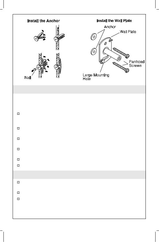
3. Anchor Installation
NOTE: You may need to disassemble some of the accessories. Some accessories will be packed with the wall plate installed in the post. Loosen the setscrew and remove the wall plate if needed.
Press and hold the legs of a wall anchor (provided) together and insert the wall anchor legs into the hole. Insert all wall anchors into the pre-drilled mounting holes.
With a hammer, carefully tap each wall anchor until they are ¯ush with the ®nished surface.
If the wall anchor was inserted into a space between the studs, it will be necessary to spread the wall anchor legs.
To spread the anchor legs, insert a thin long object, such as a ®nishing nail, into the wall anchor hole.
Repeat for all wall anchors inserted between studs.
Ensure that the wall anchors are ¯ush with the ®nished surface.
4. Wall Plate Installation
Orient the wall plate with the large slotted mounting hole down and the smaller hole over the higher anchor.
Secure the wall plate with the supplied panhead screws.
Repeat at each wall plate location.
1020823-2-A |
6 |
Kohler Co. |
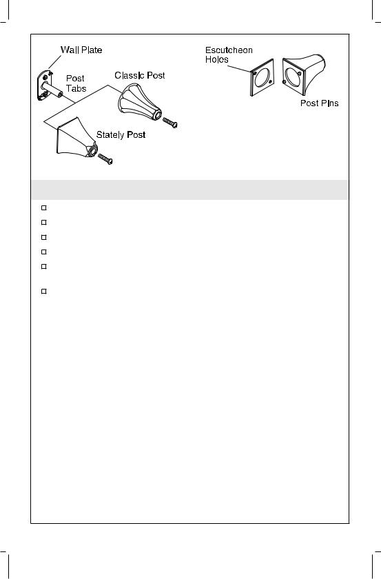
5. Install the Bonnet
Start a setscrew into each post. Do not thread fully into the posts. Position the escutcheon(s), if included, onto the post(s).
Slide the post onto the wall plate.
Position the setscrew hole in the post so it faces downward.
Make sure the post tabs engage the indexing holes in the back of the post or escutcheon.
Insert a 1² (2.5cm) screw into the post and tighten.
NOTE: When installing ªStatelyº accessories, make sure that the post pins engage the escutcheon holes.
Kohler Co. |
7 |
1020823-2-A |

6. Install Single-Post Accessories
WARNING: Risk of personal injury and product damage.
Improper mounting of the accessory may cause damage to the glass. Wall plates must be properly aligned and securely anchored.
Loosen the setscrew in the post until the cylinder head slides out of the post.
Slide the shaft of the cylinder head into the post.
Position the detent in the cylinder head shaft facing downward.
Use a hex wrench to thread a setscrew into the skirt and tighten the setscrew until the cylinder head is securely in place.
If needed, insert the tissue spindle into the tissue holder assembly.
Slide the applicable accessory into the slot in the bracket sleeve.
Tighten the setscrew using a hex wrench.
1020823-2-A |
8 |
Kohler Co. |
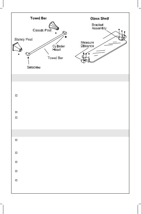
7. Install the Towel Bar
IMPORTANT! Do not overtighten the setscrews. Overtightening can damage the towel bar.
Use a hex wrench to thread a setscrew into each of the cylinder inserts and tighten. Both cylinder inserts should face in the same direction. The detent on both cylinder inserts should face straight down.
Insert the cylinder head inserts into the skirts.
Use a hex wrench to insert a setscrew into both of the skirts. Tighten the setscrews until the cylinder shafts are securely in place.
8. Install the Glass Shelf
Slide a bracket assembly onto each end of the shelf. Make sure both brackets are centered on the shelf and the setscrew holes are on the same side.
Using a hex wrench, insert four nylon tipped setscrews (provided) into the bracket assembly and tighten securely.
Install a cylinder head onto each stem of the bracket assembly as shown.
Thread a setscrew into each cylinder head and tighten with a hex wrench.
Measure the distance between the centers of the cylinder head shafts.
Kohler Co. |
9 |
1020823-2-A |

Install the Glass Shelf (cont.)
Install the wall brackets and posts using the measured dimension. The side of the bracket with the setscrew holes should face down.
1020823-2-A |
10 |
Kohler Co. |
Guide de l'Installation
Accessoires
Outils et matériaux
Niveau à |
|
|
|
Bulles |
Crayon |
Mètre Ruban |
|
|
|
|
Charpentier |
Tournevis |
Perceuse |
|
|
avec Méche |
|
||
Variés |
de 5/16" |
Clés Hexagonales |
Clé à Molette |
|
|
||
|
|
Variées |
|
Merci d'avoir choisi la Société Kohler
Nous apprécions votre engagement envers la qualité de KOHLER. S'il vous plaît, veuillez lisez attentivement ce Guide de l'Installation avant de commencer votre installation. En cas de problème avec l'installation ou de fonctionnement, n'hésitez pas à nous contacter. Notre numéro de téléphone et notre adresse de site Internet sont au verso de ce Guide de l'Installation. Merci encore d'avoir choisi la Société KOHLER.
Avant de Commencer
DANGER : Risque de blessure. Ces accessoires ne sont pas destinés ou conçus pour servir de barre d'appui ou de main courante. N'installez pas ces accessoires dans un endroit où ils pourraient être utilisés de cette façon par inadvertance.
Il est préférable d'installer ces accessoires sur un support mural. Ces accessoires peuvent être installés sur différentes surfaces, mais l'installation sur un support mural sera plus solide.
Utilisez un niveau à bulles pour vous assurer que les axes centraux des plaques murales et des montants sont de niveau.
La Société KOHLER se réserve le droit d'apporter des modi®cations à la conception des accessoires sans préavis, comme spéci®é dans le Catalogue des Prix.
Kohler Co. |
Français-1 |
1020823-2-A |
 Loading...