


KOHLER K-9531, K-9532, K-9533, K-9534, K-9535 User Manual
...Installation Guide
Single Threshold Acrylic Shower Receptors
K-9531, K-9532, K-9533,
K-9534, K-9535, K-9536,
K-9538, K-9852, K-9858,
K-9861, K-9866
M product numbers are for Mexico (i.e. K-12345M)
Los números de productos seguidos de M corresponden a México (Ej. K-12345M)
Français, page ªFrançais-1º Español, página ªEspañol-1º
1030520-2-A
Thank You For Choosing Kohler Company
We appreciate your commitment to Kohler quality. Please take a few minutes to review this manual before you start installation. If you encounter any installation or performance problems, please don't hesitate to contact us. Our phone numbers and website are listed on the back cover. Thanks again for choosing Kohler Company.
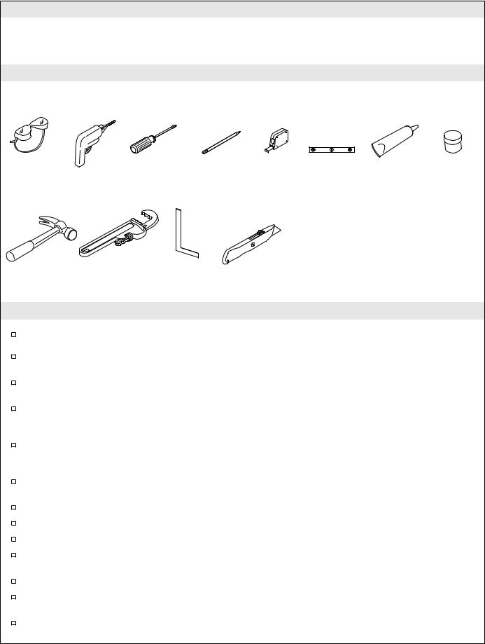
Tools and Materials
Safety |
Drill |
Screwdriver |
Pencil |
Tape |
Level |
Sealant |
Plumbers |
|
Glasses |
|
|
|
|
Measure |
|
|
Putty |
|
|
|
|
|
|
Plus: |
|
|
|
|
|
|
|
|
• Common Woodworking |
|
|
|
|
|
|
|
|
Tools and Materials |
|
|
|
|
|
|
|
|
• Nails/Drywall Screws |
|
|
|
|
|
|
|
|
• Drop Cloth |
|
|
|
|
|
|
|
|
• 2 x 4s or 2 x 6s |
|
|
Claw |
Pipe |
|
Square |
|
Knife |
• Water Resistant Wall Material |
||
|
|
• Furring Strips |
|
|
||||
Hammer |
Wrench |
|
|
|
||||
|
|
|
|
|
|
|||
Before You Begin
Observe all local plumbing and building codes.
Locate the rough plumbing for the drain in accordance with the roughing-in dimensions for your particular model.
A variety of installations are possible. These instructions show suggested installation procedures, your particular installation may require other construction techniques.
Please read these instructions carefully to familiarize yourself with the required tools, materials, and installation sequences. Follow the sections that pertain to your particular installation. This will help you to avoid costly mistakes.
Your shower receptor comes packaged in a single carton containing a one-piece shower receptor. This carton will ®t through any standard door. You should not remove the receptor from the package until you are ready to install it.
Unpack and inspect the shower receptor for damage. If you ®nd any damage, do not install the receptor. Report the speci®c problem to your dealer immediately.
After inspection, return the receptor to the carton until you are ready to install it.
You must install this shower receptor to an adequately supported, level sub¯oor.
Be sure that you have enough access to move the receptor into the construction area.
Make sure the installation area is clean and free of all debris. If remodeling, remove all ®nished wall material to expose the framing and remove all ¯oor coverings to expose the sub¯oor.
Provide properly dimensioned framing.
Alcove installation is recommended for this receptor. A drop-in installation is also an option for this receptor.
Corner or alcove installation is dependent upon the receptor model.
1030520-2-A |
2 |
Kohler Co. |

Before You Begin (cont.)
Exact location of the end studs will depend on the thickness of the ®nished wall material.
If installing this unit adjacent to vertical ducts or chases, surround the unit with ®re-rated water-resistant wall material.
When ®re-rated wall is speci®ed, stud-opening dimensions are toward the exposed side of the wall material.
Place the receptor within the installation area prior to completion of the framing.
The basin area requires no additional support when the sub¯oor is level and square with respect to the framing. Consider using shims for additional support if the sub¯oor is uneven.
Consult all applicable instructions for options and accessories before beginning this installation.
Fixture conforms to ANSI Standard Z124.2. All dimensions are nominal. All models meet IAPMO requirements with the exception of K-9531.
1. Prepare the Site
Ensure that the installation area is clean and free of all debris. If remodeling, remove all ®nished wall material to expose the framing and remove all ¯oor coverings to expose the sub¯oor.
Inspect the ¯ooring at the installation site. Repair as necessary.
Make sure the sub and ®nished ¯oors are ¯at and level.
Kohler Co. |
3 |
1030520-2-A |

C
D |
B |
A |
E |
F |
K-9531, K-9532, K-9533,
K-9534, K-9535, K-9538,
K-9852, K-9861, K-9858
C |
D |
A |
B |
A |
E |
F |
K-9536 |
K-9866 |
Diagrams shown are representative and for use with the table only.
Your fixture may appear different from the illustrations.
2. Roughing-In Dimensions
|
A |
B |
C |
D |
E |
K-9531 |
32² (81.3cm) |
16² (40.6cm) |
31-3/4² 80.6cm) |
15-7/8² (40.3cm) |
6-1/8² (15.6cm) |
K-9532 |
36² (91.4cm) |
18² (45.7cm) |
35-5/8² (90.5cm) |
17-13/16² |
6-1/8² (15.6cm) |
|
|
|
|
(45.2cm) |
|
K-9533 |
42² (106.7cm) |
21² 53.3cm) |
41.75² (106cm) |
21² (53.3cm) |
6-1/8² (15.6cm) |
K-9534 |
47-7/8² |
23-15/16² |
34² (86.4cm) |
17² (43.2cm) |
6-1/8² (15.6cm) |
|
(121.6cm) |
(60.8cm) |
|
|
|
K-9535 |
60² (152.4cm) |
30² (76.2cm) |
34² (86.4cm) |
16-7/8² (42.9cm) |
6-1/8² (15.6cm) |
K-9536 |
37-7/8² (96.2cm) |
18-13/16² |
37-7/8² (96.2cm) |
18-13/16² |
6-1/8² (15.6cm) |
|
|
(47.8cm) |
|
(47.8cm) |
|
K-9538 |
42² (106.7cm) |
21² (53.3cm) |
34² (86.4cm) |
17² (43.2cm) |
6-1/8² (15.6cm) |
K-9852 |
60² (152.4cm) |
30² (76.2cm) |
36² (91.4cm) |
27-1/8² (68.9cm) |
6-1/8² (15.6cm) |
K-9858 |
36² (91.4cm) |
8-7/8² (22.5cm) |
36² (91.4cm) |
27² (68.6cm) |
6-1/8² (15.6cm) |
K-9861 |
48² (121.9cm) |
24² (61cm) |
36² (91.4cm) |
27² (68.6cm) |
6-1/8² (15.6cm) |
K-9866 |
38² (96.5cm) |
21-7/8² (55.6cm) |
38² (96.5cm) |
18-5/8² (47.3cm) |
6-1/8² (15.6cm) |
|
|
|
|
|
|
IMPORTANT! All dimensions are nominal. The stud opening tolerance is plus 1/4² (6mm) and minus 0. Carefully measure your ®xture before determining enclosure size. When a ®re rated wall is speci®ed, dimensions are to the inside of the wall board. Some shimming between the stud frame and the ®xture may be required. Dimensions given in the roughing-in information are crucial for proper installation. Construct the framing and plumbing accurately.
NOTE: If a ®rewall is required, roughing-in dimensions will have to increase according to the thickness of the ®rewall material. Stud opening dimensions must be measured toward the exposed side of the wall material.
NOTE: If installing this unit to a masonry wall, make provisions for plumbing connections. Construct a separate frame wall a minimum of 6º (15.2cm) from the masonry wall.
1030520-2-A |
4 |
Kohler Co. |

Construct 2 x 4 stud framing according to the roughing-in information
Position the rough plumbing
Verify that the subfloor offers adequate support, and is flat and level
2 x 4 Stud Framing
Masonry Wall


 6" (15.2cm) MIN.
3. Construct the Stud Framing
If you will be installing a shower door with this unit, refer to the shower door installation instructions for any special framing considerations.
Construct 2x4 or 2x6 stud framing according to the roughing-in information for your particular model.
Verify that the framing is square and plumb.
If grab bars are to be installed, provide 2x6 bridging or attachment at speci®ed positions. Refer to the grab bar manufacturer's instructions.
The basin area requires no additional support when the sub¯oor is plumb and level with respect to the stud framing. If the sub¯oor is not level, shimming may be required to level the unit.
Kohler Co. |
5 |
1030520-2-A |

2" (5cm) Drain Pipe |
3/8" (1cm) |
|
Wood Sub-Floor |
4-1/2" (11.4cm) D. MIN. |
|
2" (5cm) Drain Pipe |
3/8" (1cm) |
|
|
1-1/2" (3.8cm) |
Concrete Sub-Floor |
|
MIN. |
4-1/2" (11.4cm) D. MIN. |
|
4. Install the Plumbing
NOTE: Provide access to all plumbing connections to simplify future maintenance.
Locate rough plumbing for the drain according to the correct model's roughing-in dimensions.
Position the plumbing according to the roughing-in information. Cap the supplies and check for leaks.
Install a 2º (5cm) drain pipe to extend 3/8º (1cm) above the sub¯oor or slab. A pocket is required in a slab construction to accommodate the drain ®tting.
If possible, provide an access at the back of the plumbing wall for servicing the supply and waste piping.
Install the shower valving according to the manufacturer's instructions. Do not install the trim at this time.
1030520-2-A |
6 |
Kohler Co. |

|
Water-Resistant |
|
Wall Material |
Unfinished Wall |
Finished Wall |
|
Water-Resistant |
|
Sealer |
Vinyl Tiling-In |
Pressure-Sensitive |
Bead |
Tape |
|
Receptor Rim |
|
Sub-Floor |
5. Install the Vinyl Tiling-in Bead
CAUTION: Risk of product damage. Do not apply the vinyl tiling-in bead or pressure-sensitive tape in temperatures below 40°F (4.4°C).
NOTE: The K-1182 vinyl tiling-in bead is used for the corner installations of the K-9852 and K-9861 shower receptors. There is enough vinyl tiling-in bead supplied for either receptor. Some cutting will be required.
The vinyl bead takes the place of the ¯ange on the side(s) of the receptor and is necessary to prevent water from seeping into the framing. The installation kit contains a 7' (2.1 m) vinyl bead and a 12' (3.7 m) strip of pressure-sensitive sealing tape.
Clean the receptor rim of all dust, grease and foreign matter.
Temporarily position the tiling-in bead on the receptor to measure. Do not use the sealing tape at this time. The bead should start 3/4º (1.9cm) back from the front corner and extend along the rim all the way to the integral tiling-in ¯ange at the rear of the receptor. Cut the length to ®t.
Cut the same length(s) of pressure-sensitive tape, also starting from the front edge of the rim.
Apply the vinyl tiling-in bead just before moving the receptor into position.
Remove the paper backing from the pressure-sensitive tape and carefully apply the tape to the corner radius of the receptor.
Start applying the vinyl bead 3/4º (1.9cm) back from the front corner. Press the bead ®rmly against the sealing tape for proper sealing.
Repeat procedure working toward the opposite end.
After the bead is in place, start at the area where the bead was ®rst applied and rub ®rmly with the heel of your hand to ensure a continuous seal.
6. Prepare the Receptor
CAUTION: Risk of product or property damage. If a watertight seal on the drain is not obtained, water damage to the receptor bottom and the sub¯oor may occur.
Install the drain to the shower receptor according to the drain manufacturer's instructions.
Clean the receptor to reduce the risk of surface damage.
Place a clean drop cloth or other similar material into the bottom of the receptor. Be careful not to scratch the surface of the unit.
Kohler Co. |
7 |
1030520-2-A |

7. Position the Receptor
Move the receptor into position. Verify proper ®t.
Fit the drain into the trap. Do not connect the trap at this time.
CAUTION: Risk of product damage. If shimming is required, shim between the sub¯oor or slab and the wood block feet on the underside of the receptor. All wood block feet must be supported when the
receptor is leveled and nailed to the framing.
Check that the receptor is level in both directions and resting on all feet. Shim if necessary.
Concrete, gypsum cement or other similar materials can be used to level the base.
1030520-2-A |
8 |
Kohler Co. |

Stud
Use #6 large-head galvanized nails or screws to secure the nailing-in flange to the studs
Drill a small
hole through the Stud Furring Strip nailing-in flange
at each stud
Nailing-In Flange
8. Secure the Receptor to the Stud Framing
 CAUTION: Risk of property damage. Make sure a watertight seal exists on all drain connections.
Drill 1/8º (3mm) pilot holes through the nailing±in ¯ange at each stud location. If needed, shim between the nailing-in ¯ange and the studs to prevent cracking the ¯ange when drilling.
Complete the drain installation according to the instructions packed with the drain. Open the water supplies and check all the connections for leaks.
Run water into the receptor and check the drain connections for leaks.
Use #6 large-head galvanized nails or screws to secure the nailing-in ¯ange to the studs.
Nail 1/8º (3mm) thick furring strips to the studs to shim out to the edge of the nailing-in ¯ange.
Kohler Co. |
9 |
1030520-2-A |

1/2" (1.3cm) |
|
|
Water-Resistant |
|
|
Wall Material |
2 x 4 Framing |
|
Edge |
|
|
(Paperboard) |
|
|
Down |
1/8" (3mm) |
|
1/4" (6mm) |
||
Furring |
||
|
Galvanized |
|
|
Nail |
|
Concave Surface |
|
Water Resistant Sealer Between Nailing-in Flange And
Paperbound Edge Of Water-Resistant Wall Material
9. Complete the Installation
Apply silicone sealant to the upper portion of the nailing-in ¯ange/vinyl bead where it will meet the water-resistant wall material.
Cover the framing, walls and nailing-in ¯ange with water-resistant wall material.
Install the water-resistant wall material to the framing with the paperbound edge a maximum of 1/4º (6mm) above the ®nished concave surface of the receptor.
Tape and mud the wall material.
Install the ®nished wall. Seal the joints between the receptor rim and the ®nished wall with silicone sealant. RTV (Room Temperature Vulcanizing) sealant is recommended.
Seal around the valving and outlets with silicone sealant or plumbers putty.
Install the faucet and drain trim according to the manufacturer's instructions.
If used, install the grab bars or towel bars to the backing in the stud wall (previously installed). Follow the manufacturer's installation instructions.
If used, install the shower door according to the manufacturer's instructions.
Install the ®nished ¯oor. Apply silicone sealant along the front edge of the receptor where it meets the ¯oor.
10. Clean-Up
CAUTION: Risk of product damage. Do not allow cleaners containing petroleum distillates to remain in contact with module surfaces for any length of time.
 CAUTION: Risk of product damage. Do not use abrasive cleaners.
When cleaning up after installation, use warm water and an approved liquid cleanser to clean the surface.
Stubborn stains, paint or tar can be removed with turpentine or paint thinner.
Plaster can be removed by scraping with a wood edge. Do not use metal scrapers, wire brushes, or other metal tools. Use warm water and an approved liquid cleanser to provide mild abrasive action to remove residual plaster.
1030520-2-A |
10 |
Kohler Co. |
 Loading...