


Installation and Care Guide
In-Wall Tank and Carriage
K-18829
M product numbers are for Mexico (i.e. K-12345M) Los números de productos seguidos de
M corresponden a México (Ej. K-12345M)
Français, page “Français-1” Español, página “Español-1”
1246750-2-B
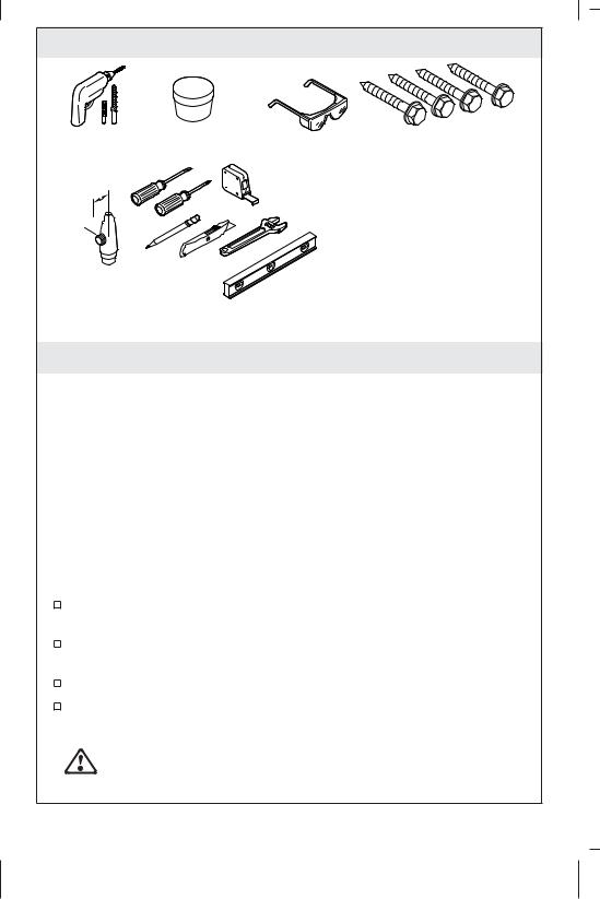
Tools and Materials
Assorted Drill Bits Silicone Plumbers Grease
5/8" (16 mm)
1/2" 
1/4 turn, 1/2" NPT Supply Shut-off with 5/8" or Shorter Handle
1/4" x 2" (51 mm) Min Lag Bolts
Plus:
•Conventional woodworking tools and materials
•1/4" x 2" (51 mm) Min Concrete Expansion Bolts (for concrete subflooring)
Optional:
• Assorted electrical tools
Before You Begin
IMPORTANT! 2x4 framing is required for this product.
IMPORTANT! In areas with freezing temperatures, install on an interior wall. If installed on an exterior wall, provide adequate insulation to prevent the possibility of freezing.
NOTE: If 2x6 framing is used, the drain outlet may be angled 45 degrees in either direction.
NOTE: This device is not intended to be used as a retrofit device for 1.28 gpf (4.8 lpf) water closets.
NOTE: Performance may vary. This product was tested with toilets that are listed as compatible.
Only bowl numbers K-6299 and K-6300 are compatible with the carriage.
During installation, make sure the inlet tube connections and gaskets remain fully engaged to ensure a watertight seal.
Carefully inspect the carriage and tank for damage.
Observe all local plumbing and building codes.
For Installations with a Bidet Seat
CAUTION: Risk of personal injury. If the optional electrical outlet will be installed, it must be connected to a GFCI or RCD protected circuit.
1246750-2-B |
2 |
Kohler Co. |

Before You Begin (cont.)
If the optional electrical outlet will be installed, observe all local electrical codes.
Kohler Co. |
3 |
1246750-2-B |
2x4 Studs or
2x6 Studs PVC 
 Elbow
Elbow
|
|
|
|
|
|
|
|
|
|
|
|
|
|
|
|
1-3/4" (44 mm) [2x4 Studs] |
|
|
|
|
|
|
|
|
|
|
|
|
|
|
|
|
|
|
|
|
|
|
|
|
|
|
|
|
|
|
|
|
|
|
|
|
|
|
|
|
|
|
|
|
|
|
|
|
|
|
|
|
|
|
|
|
23-1/4" |
|
|
|
|
|
|
|
|
|||
|
|
|
|
|
|
|
|
|
|
|
|
|
3-1/4" (83 mm) [2x6 Studs] |
|||
|
|
|
|
|
(591 mm) |
|
|
|
|
|
|
|
||||
|
|
|
|
|
|
|
|
|||||||||
|
|
|
|
|
|
|
|
|
|
|
|
|
|
|
|
|
|
|
|
|
|
|
|
|
|
|
|
|
|
|
|
|
|
Waste |
|
|
|
|
|
1-3/4" (44 mm) [2x4 Studs] |
||||||||||
Outlet |
|
|
|
|
|
|
||||||||||
|
|
|
|
|
3-1/4" (83 mm) [2x6 Studs] |
|||||||||||
Pipe |
|
|
|
|
|
|
||||||||||
|
|
|
|
|
|
|
|
|
|
|
|
|
|
|||
8" (203 mm) [Plywood Subfloor] 9-1/8" (232 mm) [Concrete Subfloor]
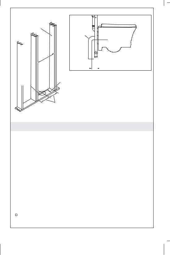
1. Install the Framing
IMPORTANT! Note the 1-3/4″ (44 mm) or 3-1/4″ (83 mm) dimension from the front edge of the framing to the center of the outlet pipe depending on your installation. This dimension is critical for the installation.
NOTE: Refer to the specification sheet for more details and dimensions for roughing-in.
NOTE: The waste outlet pipe may need to be relocated for this installation.
NOTE: A PVC elbow is supplied with this product. A cast iron elbow may be required by codes in some areas. The height of the toilet drain pipe may need to be adjusted if the cast iron elbow is used.
NOTE: Double studs must be used on either side of the stud pocket.
Construct the stud pocket using the dimensions shown.
1246750-2-B |
4 |
Kohler Co. |

Install the Framing (cont.)
The center of the waste outlet should be 1-3/4″ (44 mm) or 3-1/4″ (83 mm) from the front edge of the framing.
Kohler Co. |
5 |
1246750-2-B |

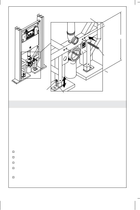
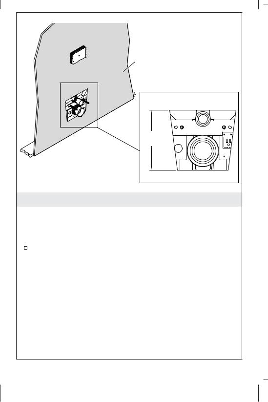
Mounting
Front View |
Frame |
Back View |
PVC
Elbow
Drain
Clamp
Electrical
Box
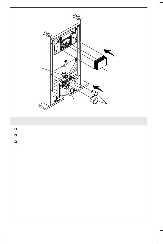
2. Prepare the Carriage
Install the Drain Clamp
Unpack and inspect the carriage.
NOTE: If using 2x6 studs, install the mounting frame reversed into the back notches.
Install the mounting frame into the front notches on the bottom of the carriage.
Insert the PVC elbow into the mounting frame.
Secure the elbow in place with the drain clamp. Push the clamp into the frame until it locks into place.
Install the Electrical Box - Bidet Installations
NOTE: The 1201721 electrical box kit is required when the K-4744 bidet seat will be paired with the bowl. Skip this step for standard installations.
Connect the electrical box to the carriage at the location shown.
1246750-2-B |
6 |
Kohler Co. |
Mark the carriage.
 2-5/8"
  (67 mm)
A


 Threaded
Rods
Finished
Floor
Nut
Leg
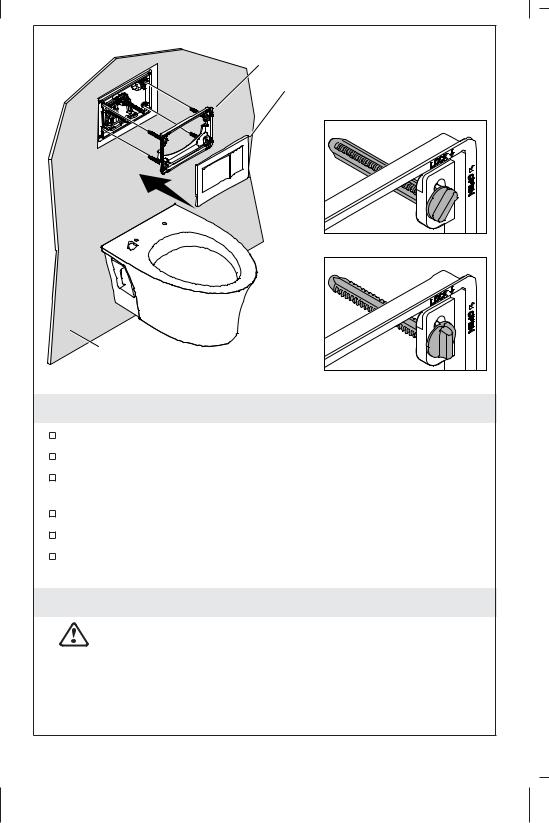
3. Adjust the Carriage Height
IMPORTANT! If the carriage is not correctly adjusted, the bowl rim height may not be compliant with applicable codes. The finished wall would need to be removed to make the correct adjustments if the bowl height is not correct.
NOTE: For the K-6299 and K-6300 bowls, the minimum rim height is 15″ (381 mm) when the finished floor is even with the bottom of the carriage legs. The maximum rim height is 23″ (584 mm) when the legs are fully raised. The carriage can be adjusted up to 8″ (203 mm), with 6″ (152 mm) or less of adjustment sufficient in most installations.
Move the carriage into place in the stud pocket.
Temporarily secure the carriage in place so it will not fall.
Install the threaded rods several turns into the carriage.
Make a mark on the carriage 2-5/8″ (67 mm) above the top of the threaded rod.
Measure from the finished floor to the mark (A) to determine the rim height of the bowl.
Kohler Co. |
7 |
1246750-2-B |

Adjust the Carriage Height (cont.)
Loosen the nuts securing the legs to the carriage.
NOTE: As the carriage is lowered, make sure the elbow aligns with the toilet drain pipe.
NOTE: If applicable, confirm the gasket on the elbow stays correctly positioned as it enters the toilet drain pipe.
Adjust the carriage until the desired height is reached. Securely tighten the nuts using a wrench to secure the legs in place.
NOTE: If a cast iron elbow is required, make the connections following all applicable codes.
1246750-2-B |
8 |
Kohler Co. |

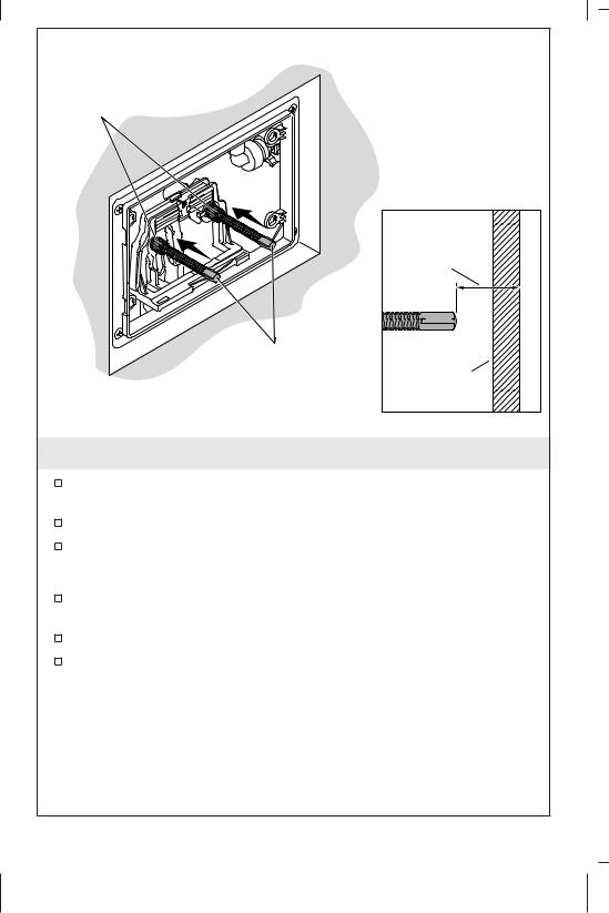
Lag Bolts
4. Install the Carriage
Align the carriage flush with the front edge of the studs. The front of the carriage should be flush with the front edge of the studs or set back slightly for finished wall installation.
Check the front of the carriage for plumb.
Mark the hole locations for the six lag bolts, one for each foot and two on either side of the carriage.
Drill pilot holes (remove the carriage if needed) to reduce the risk of the lag bolts causing the studs to split or crack.
NOTE: If the carriage is installed onto a concrete sub-floor use concrete expansion bolts (not supplied) when securing the feet of the carriage.
Secure the carriage to the support studs using 2″ (51 mm) long (minimum) lag bolts (not supplied), one at each location.
Connect the Power - Bidet Seat Installations
WARNING: Risk of personal injury. Disconnect the power before connecting the wires.
Kohler Co. |
9 |
1246750-2-B |
Install the Carriage (cont.)
CAUTION: Risk of personal injury. The electrical outlet must be connected to a GFCI or RCD protected circuit or an accessible Ground-Fault Circuit-Interrupter (GFCI) or Residual-Current Device (RCD) must be installed.
NOTE: This step is only needed if the electrical box was installed in the ″Prepare the Carriage″ section.
Connect the power following all applicable codes.
1246750-2-B |
10 |
Kohler Co. |
Bidet Water Supply (Optional)
1/2" NTP
Adapter
|
|
|
|
|
|
|
|
|
|
|
|
|
|
|
|
|
|
|
|
|
|
|
|
|
|
|
|
|
|
|
|
|
|
|
|
|
|
|
|
|
|
|
|
|
|
|
|
|
|
|
|
|
|
|
|
|
|
|
|
|
|
|
|
|
|
|
|
|
|
|
|
|
|
|
5/8" |
||||
|
|
|
|||||
4" (102 mm) |
|
|
|
(16 mm) |
|||
|
|
|
Max |
||||
Maximum Clearance |
|
|
|
||||
|
|
|
|
|
|||
from the Front of |
|
|
|
|
|
||
the Finished Wall |
|
|
|
|
|
||
5. Install the Water Supply
All Installations
IMPORTANT! Optional bidet water supply is shown. Do not install a second water supply unless a bidet seat will be installed.
Install the water supply pipes, following all local codes.
Connect the waste pipe following all applicable local codes.
If using a G 1/2 connection, remove the 1/2″ NTP adapter and discard.
Installations With a Bidet Seat
Optional: Install the bidet water supply and a quarter turn, 1/2″ NPT supply shut-off.
IMPORTANT! The bidet supply shut-off must extend 3″ (76 mm) minimum to 4″ (102 mm) maximum from the finished wall to allow access to the handle. The supply shut-off handle should be no higher than 5/8″ (16 mm) from the center of the water supply.
Kohler Co. |
11 |
1246750-2-B |
Inlet
Hole
Flush Shield
Outlet |
|
Hole |
Plaster Guard |
6. Install the Plaster Guards
Insert a plaster guard into the inlet hole in the carriage.
Install a plaster guard into the outlet hole in the carriage.
Install the flush shield in the flush valve opening by snapping it into place.
1246750-2-B |
12 |
Kohler Co. |
Finished Wall
Front View
 10-1/2" (267 mm)

9-1/4"
(235 mm)
 8" (203 mm)

7. Install the Finished Wall
NOTE: It is recommended to use cement board or tile backer board for the wallboard backing. Gypsum board can also be used but it may affect the toilet loading strength.
NOTE: The wall thickness should not exceed 2-3/4″ (70 mm).
Install the finished wall.
Kohler Co. |
13 |
1246750-2-B |
Utility Knife |
Flush Shield |
Finished Wall
8. Trim the Flush Shield
Use a utility knife to carefully trim the flush shield even with the finished wall.
1246750-2-B |
14 |
Kohler Co. |
Flush Valve Opening
Service Cover
Tabs
9. Remove the Service Cover
Remove and discard the service cover by pressing down on the tabs and pulling forward.
Kohler Co. |
15 |
1246750-2-B |
Push Rod
Nuts
Push Rods
Side View
1/2" |
(13 mm) |
Min |
Finished |
Wall |
10. Install the Actuator
Thread the push rods into the actuator assembly 1/2″ (13 mm) behind the finished wall.
If needed, trim the threaded end of the push rods.
Secure the push rods in place with the push rod nuts.
K-4177, K-8857 and K-5413
Thread the push rods into the actuator assembly flush with the finished wall.
If needed, trim the threaded end of the push rods.
Secure the push rods in place with the push rod nuts.
1246750-2-B |
16 |
Kohler Co. |
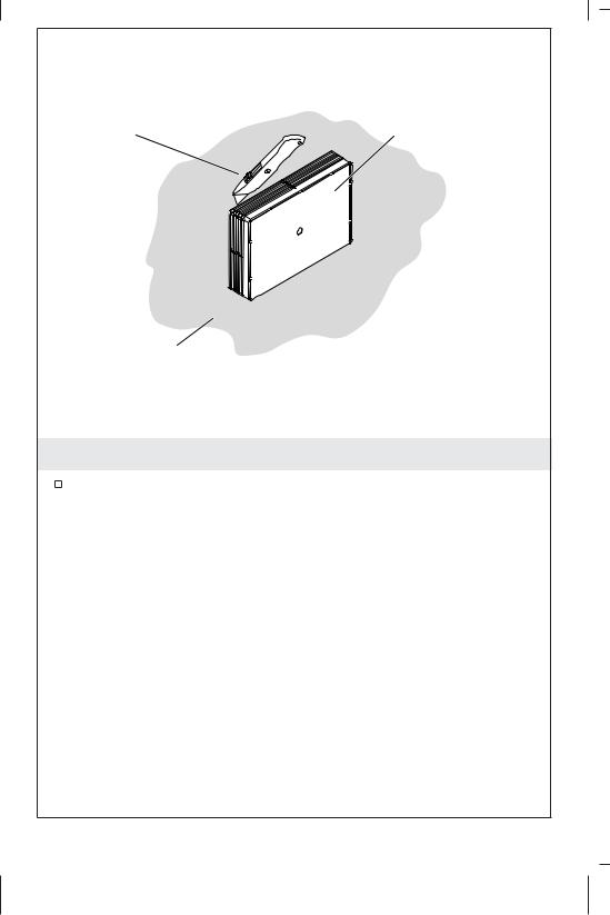
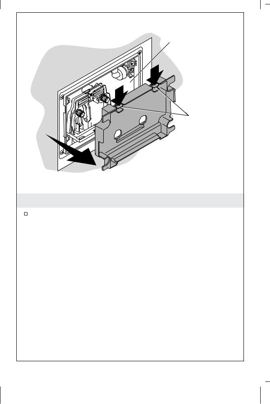
Mounting Frame
Faceplate
Open Position
Lock Position
Finished
Wall
11. Install the Faceplate
Install the locking pins into the mounting frame.
Turn the locking pins to the ″Open″ position.
Align the mounting frame with the tank mounting opening and install the frame.
If needed, trim the locking pins.
Turn the locking pins to the ″Lock″ position.
Position the faceplate over the lift rod assembly and press into place.
Care and Cleaning
WARNING: Risk of property or product damage. Do not use in-tank cleaners in your toilet. Products containing chlorine (calcium hypochlorite) can seriously damage fittings in the tank. This damage can cause leakage and property damage.
Kohler Co. shall not be responsible or liable for any tank fitting
Kohler Co. |
17 |
1246750-2-B |

Care and Cleaning (cont.)
damage caused by the use of cleaners containing chlorine (calcium hypochlorite).
For best results, keep the following in mind when caring for your KOHLER product:
•Always test your cleaning solution on an inconspicuous area before applying to the entire surface.
•Wipe surfaces clean and rinse completely with water immediately after applying cleaner. Rinse and dry any overspray that lands on nearby surfaces.
•Do not allow cleaners to soak on surfaces.
•Use a soft, dampened sponge or cloth. Never use an abrasive material such as a brush or scouring pad to clean surfaces.
•For Artist Edition Toilets: Treat your decorative product just as you would treat your fine china. DO NOT use bristle brushes or abrasive-backed sponges. They will scratch decorative surfaces.
Use only warm water to clean. Dry with a cotton cloth or soft sponge.
For detailed cleaning information and products to consider, visit www.kohler.com/clean. To order Care & Cleaning information, call 1-800-456-4537.
Troubleshooting
For service parts information, visit www.kohler.com/serviceparts.
Symptoms |
Cause |
Recommended Action |
||
1. Poor flush. |
A. |
Water level is |
A. |
The water line should |
|
|
too low. |
|
be about 8″ (203 mm) |
|
|
|
|
above the bottom of |
|
|
|
|
the tank. Raise the |
|
|
|
|
water level in the tank |
|
|
|
|
to the marked |
|
|
|
|
waterline by turning |
|
|
|
|
the white knob |
|
|
|
|
clockwise until the |
|
|
|
|
water level reaches the |
|
|
|
|
waterline marked in |
|
|
|
|
the tank. |
|
B. |
Improper waste |
B. |
Install venting to code. |
|
|
line venting. |
|
|
|
|
|
|
|
|
|
|
|
|
1246750-2-B |
|
18 |
|
Kohler Co. |

Troubleshooting (cont.) |
|
|
|
||
|
|
|
|||
Symptoms |
Cause |
Recommended Action |
|||
2. |
Running fill |
A. |
Water level is |
A. |
Lower the water level |
|
valve. |
|
too high. |
|
in the tank by turning |
|
|
|
|
|
the knob at the top of |
|
|
|
|
|
the threaded rod |
|
|
|
|
|
counterclockwise until |
|
|
|
|
|
the fill valve shuts off |
|
|
|
|
|
when the water level |
|
|
|
|
|
reaches the marked |
|
|
|
|
|
waterline in the tank. |
|
|
B. |
Flush valve |
B. |
Replace gasket or |
|
|
|
gasket or flush |
|
flush valve as |
|
|
|
valve are |
|
necessary. |
|
|
|
damaged. |
|
|
|
|
C. |
Flush valve is |
C. |
Check flush valve and |
|
|
|
sticking open. |
|
actuating mechanisms |
|
|
|
|
|
for free movement. |
|
|
|
|
|
Push button actuators |
|
|
|
|
|
should raise levers |
|
|
|
|
|
then spring back |
|
|
|
|
|
without force. Replace |
|
|
|
|
|
components as |
|
|
|
|
|
necessary. |
3. |
Leaks from |
A. |
Gaskets not |
A. |
Remove the bowl and |
|
behind the bowl. |
|
positioned |
|
inspect all the gaskets. |
|
|
|
correctly. |
|
Reposition the gaskets |
|
|
|
|
|
if needed. Lubricate |
|
|
|
|
|
the gaskets so they |
|
|
|
|
|
slide over the mating |
|
|
|
|
|
part they seal. |
|
|
|
|
|
Reinstall the bowl, |
|
|
|
|
|
making sure the |
|
|
|
|
|
gaskets stay in the |
|
|
|
|
|
correct positions. |
4. |
Carriage and |
A. |
Insufficient |
A. |
Add additional |
|
bowl flex when |
|
support for |
|
support members, and |
|
used. |
|
frame. |
|
mount the frame with |
|
|
|
|
|
1/4″ or larger lag |
|
|
|
|
|
screws. |
5. |
No water flow. |
A. |
Supply stop |
A. |
Open the supply stop |
|
|
|
located in tank |
|
(located on the left |
|
|
|
is closed. |
|
side). |
|
|
|
|
|
|
|
|
|
|
|
|
Kohler Co. |
|
19 |
|
1246750-2-B |
|

Troubleshooting (cont.)
Symptoms |
Cause |
Recommended Action |
|
B. There is an |
B. Close the external |
|
obstruction in |
supply stop, |
|
the water line. |
disconnect the braided |
|
|
hose where it attaches |
|
|
to the fill valve. Turn |
|
|
on the water supply |
|
|
and check the flow |
|
|
through the hose. |
|
|
Continue to |
|
|
investigate water path |
|
|
for obstructions. Clear |
|
|
any blockages. |
|
|
|
Warranty
ONE-YEAR LIMITED WARRANTY
KOHLER plumbing products are warranted to be free of defects in material and workmanship for one year from date of installation.
Kohler Co. will, at its election, repair, replace or make appropriate adjustment where Kohler Co. inspection discloses any such defects occurring in normal usage within one (1) year after installation. Kohler Co. is not responsible for removal or installation costs. Use of in-tank toilet cleaners will void the warranty.
To obtain warranty service contact Kohler Co. either through your Dealer, Plumbing Contractor, Home Center or E-tailer, or by writing Kohler Co., Attn.: Customer Care Center, 444 Highland Drive, Kohler, WI 53044, USA, or by calling 1-800-4-KOHLER (1-800-456-4537) from within the USA and Canada, and 001-800-456-4537 from within Mexico, or visit www.kohler.com within the USA, www.ca.kohler.com from within Canada, or www.mx.kohler.com in Mexico.
IMPLIED WARRANTIES INCLUDING THAT OF MERCHANTABILITY AND FITNESS FOR A PARTICULAR PURPOSE ARE EXPRESSLY LIMITED IN DURATION TO THE DURATION OF THIS WARRANTY. KOHLER CO. AND/OR SELLER DISCLAIM ANY LIABILITY FOR SPECIAL, INCIDENTAL OR CONSEQUENTIAL DAMAGES. Some states/provinces do not allow limitations on how long an implied warranty lasts, or the exclusion or limitation of special, incidental or consequential damages, so these limitations and exclusions may not apply to you. This warranty gives you specific legal rights. You may also have other rights which vary from state/province to state/province.
1246750-2-B |
20 |
Kohler Co. |
Warranty (cont.)
This is Kohler Co.’s exclusive written warranty.
Kohler Co. |
21 |
1246750-2-B |
 Loading...