


Installation Guide
Wall-Mount Valve
K-11830, K-11831
M product numbers are for Mexico (i.e. K-12345M) Los números de productos seguidos de
M corresponden a México (Ej. K-12345M)
Français, page “Français-1” Español, página “Español-1”
1124216-2-B

Tools and Materials
|
|
Plus: |
|
|
|
• Wire Fasteners |
|
Adjustable |
Sealant Tape |
• Woodworking Tools |
|
• Pipe Fitting Tools |
|||
Wrench |
|
||
|
• Wood Screws |
||
|
|
• 2x4s |
Assorted |
Hex Wrench |
Screwdrivers |
|
Before You Begin
NOTE: Follow the installation dimensions precisely as there is no deep rough-in kit available for this product.
Observe all local plumbing and building codes.
Shut off the main water supply.
Inspect the supply tubing for damage. Replace as necessary.
Site preparation and wall finishing may require additional tools and materials.
1124216-2-B |
2 |
Kohler Co. |

Drop-In |
1/2" |
Finished Wall |
|
Sinks |
|||
(13 mm) |
11" (279 mm) |
||
|
|||
|
|
||
|
|
Motion |
|
|
|
Zone |
|
|
|
20˚ |
|
|
Y |
X |
|
|
|
||
|
* |
|
|
|
Countertop |
||
Under-Mount
Sinks
1/2" |
Finished Wall |
(13 mm) |
11" (279 mm) |
|
|
|
Motion |
|
Zone |
|
20˚ |
Y |
X |
|
|
* |
|
Countertop |
|
Above-Counter
Sinks
Important:
Measure "Y" from the sink rim,
not the countertop.
1/2" |
|
Finished Wall |
(13 mm) |
11" (279 mm) |
|
|
|
|
|
|
Motion |
|
|
Zone |
|
|
20˚ |
|
Y |
X |
|
|
|
|
* |
|
|
Countertop |
|
* Consult the specification sheet for the spout that will be paired with this valve for specific installation dimensions.
1. Determine the Sensor Location
Kohler Co. |
3 |
1124216-2-B |

Determine the Sensor Location (cont.)
IMPORTANT! It is critical for proper operation that the sensor be installed with the motion zone clear of any obstructions, including the edge of the countertop or the bathroom sink.
NOTE: Before installation, consult the specification sheet for the spout to determine the correct wall rough-in for your installation.
Measure the distance (X) from the finished wall to the inside edge of the countertop or bathroom sink.
Determine the sensor height (Y) using the chart below. If you cannot determine Y from the chart, use the formula .5″ + X(0.364) to determine (Y).
If dimension X is: |
Then the sensor height (Y) is: |
1″ (25 mm) |
7/8″ (48 mm) |
2″ (51 mm) |
1-1/4″ (32 mm) |
3″ (76 mm) |
1-9/16″ (40 mm) |
4″ (102 mm) |
2″ (51 mm) |
5″ (127 mm) |
2-3/8″ (60 mm) |
6″ (151 mm) |
2-9/16″ (65 mm) |
7″ (179 mm) |
3″ (76 mm) |
8″ (203 mm) |
3-7/16″ (87 mm) |
9″ (229 mm) |
3-3/4″ (95 mm) |
|
|
1124216-2-B |
4 |
Kohler Co. |

|
Six Round Holes (Typical) |
|
|
Wall Plate |
|
|
Screws |
|
Finished |
16" |
|
Wall |
||
(406 mm) |
||
|
||
* |
|
|
*Consult the spout |
7" (178 mm) |
|
specification sheet |
* |
|
for specific installation |
||
|
||
dimentions. |
|
|
|
2x4 Stud Framing |
|
|
Sink Height |
2. Prepare the Site
IMPORTANT! The valve requires special framing and support considerations. Consult the specification sheet for the spout that will be installed with your valve at www.kohler.com for specific dimensions.
NOTE: Mount the valve with the sensor at the height determined in the previous step.
NOTE: A suggested framing example is shown. Each installation may have different framing requirements than those shown.
Construct the framing for your installation.
If a thermostatic mixing valve will be included with your installation, install the valve now following the directions provided with the valve.
3. Secure the Valve
IMPORTANT! Make sure the location of the valve is correct before securing it in place. The centerline of the drain and faucet should be in line with each other.
Kohler Co. |
5 |
1124216-2-B |

Secure the Valve (cont.)
Secure the wall plate to the studs using six wood screws (not provided).
1124216-2-B |
6 |
Kohler Co. |
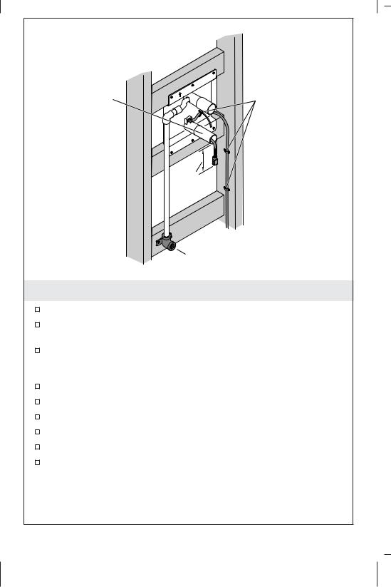
Plaster Guard |
Secure wire |
harness to the wall. |
1-1/2"
(38 mm)
Ell
4. Install the Supplies
Install 1/2″ supply pipe to the valve assembly.
At the point where the supply will exit the wall, install a drop ear ell flush or slightly behind the finished wall.
Feed the sensor wire through the sensor mount and plaster guard, leaving 1-1/2″ (38 mm) minimum of exposed wire protruding.
Connect the sensor wire harness to the wall.
Temporarily connect the water supply to the supply ell.
Turn on the water.
Check the system for leaks.
Turn off the water.
Install the finished wall.
NOTE: The diameter of the faucet hole cutout is 1-3/4″ (44 mm). The diameter of the sensor hole cutout is 1-3/8″ (35 mm).
Kohler Co. |
7 |
1124216-2-B |

Install the Supplies (cont.)
NOTE: The diameter of the supply inlet opening is determined by the ell diameter.
1124216-2-B |
8 |
Kohler Co. |

Sensor Wire
Bezel
Discard the |
Sensor |
|
plaster guard. |
||
|
5. Install the Sensor
Install the Bezel
Loosen the screws in the plaster guard.
Remove the plaster guard and discard.
Feed the sensor wire through the back of the bezel.
Position the bezel over the screw heads and turn 1/8 turn counterclockwise.
Tighten the screws.
Connect the Sensor
Connect the sensor to the wire harness and feed the wire into the wall.
Position the sensor in front of the bezel with the wire on the back of the sensor to the right.
Push the sensor into place.
Kohler Co. |
9 |
1124216-2-B |

Control Box
Screws
6. Install the Control Box
NOTE: Locate the sensor box underneath the countertop, between the ell and the water supply stop.
NOTE: Do not connect the control box wiring in this step. Drill a 1/2″ (13 mm) hole at the control box location.
Route the sensor wire through the hole.
Remove the control box cover. Keep the screws and cover.
Mark the screw hole locations using the control box as a template. Make sure the wire harness hole in the wall is covered by the box.
Install appropriate wall anchors (not provided) at the marks.
Feed the wires through the back of the valve and control box.
Attach the control box to the wall with two screws (not provided).
1124216-2-B |
10 |
Kohler Co. |

Hex Hole Outlet
Ell
Outlet
Inlet
Round Hole |
Inlet |
7. Install the Supplies
IMPORTANT! It is critical that the inlet and outlet holes be aligned correctly. The inlet hole is round, the outlet hole is hex shaped. There is a label on the outlet side identifying it.
Slide the escutcheon over the elbow and attach the elbow to the ell.
Slide the escutcheon tight against the wall.
Attach one end of the hose to the elbow and attach the other end of the hose to the control box outlet.
Attach the supply hose to the control box inlet.
NOTE: If the water supply does not route through a mixing valve, the water from the faucet will be cold.
Attach the other end of the line to a thermostatic mixing valve (recommended), mixing valve, or supply stop.
Kohler Co. |
11 |
1124216-2-B |
 Loading...