


Installation Guide
Pressure Balancing Valve
K-304 |
|
K-305 |
M product numbers are for Mexico (i.e. K-12345M)
Los números de productos seguidos de
M corresponden a México (Ej.
K-12345M)
Français, page “Français-1”
Español, página “Español-1”
114811-2-CG

IMPORTANT INSTRUCTIONS
WARNING: Risk of scalding or other severe injury.
•Before completing installation, the installer must set the maximum water temperature setting of this valve to minimize the risks associated with scalding hazards according to ASTM F 444.
•Do not install a shut-off device on either outlet of this valve. The installation of any such device may create a cross-flow condition at the valve and affect the water temperature.
•Factors that change the temperature of the water supplied to the valve, such as seasonal water temperature changes, and water heater replacement or servicing, will change the maximum water temperature supplied by the valve and may create a scalding hazard. The pressure-balanced valve will not compensate for changes in the water supply temperature; adjust the maximum water temperature setting of this pressure-balanced valve when such changes occur.
•Pressure-balanced valves may not provide protection against scalding if there is a failure of other temperature-limiting devices elsewhere in the plumbing system.
WARNING: Risk of product damage. Only silicone based lubricants should be used with these valves. Use of petroleum based lubricants on the valve is harmful to the O-rings, seals, and plastic components. Use of petroleum based lubricants will void the warranty.
The installer is responsible for installing the valve and adjusting the maximum water temperature of this pressure-balanced valve according to instructions.
This valve meets or exceeds ANSI A112.18.1 and ASSE 1016.
If you do not understand any of the installation or temperature adjustment instructions in this document, in the United States please contact our Customer Service Department at 1-800-4-KOHLER. Outside the U.S., please contact your distributor.
The PEX connections are designed for use with any ASTM F 1807 compliant copper crimp rings and ASTM F 887 compliant PEX tubing. These fittings are not compatible with ASTM F 1960 cold expansion fittings with PEX reinforcing ring assemblies.
The PEX potable fittings on this valve have been third party certified by CSA using the following: Sioux Chief 1/2” copper crimp ring and CSA certified VANGARD VANEX® 1/2” PEX potable tubing. Crimps were made using a Sioux Chief 1/2” crimp tool in accordance with the Sioux Chief instructions.
IMPORTANT NOTICE TO INSTALLERS! Please fill in the blanks in the information box in the Homeowners Guide and on the valve label. Retain the Homeowners Guide for future reference.
114811-2-CG |
2 |
Kohler Co. |

Tools and Materials
Pipe |
Adjustable |
Strap |
Hacksaw or Tubing Cutter |
|
|
|
|||
Wrench |
Wrench |
Wrench |
|
|
|
|
|
|
Propane |
|
|
|
|
Torch |
|
|
|
PEX Crimp Tool |
|
Assorted |
Plumbers |
Thread |
|
|
Screwdrivers |
Putty |
Sealant Hex |
|
|
|
|
|
Wrench |
Thermometer Solder |
Thank You For Choosing Kohler Company
We appreciate your commitment to Kohler quality. Please take a few minutes to review this manual before you start installation. If you encounter any installation or performance problems, please don’t hesitate to contact us. Our phone numbers and website are listed on the back cover. Thanks again for choosing Kohler Company.
Before You Begin
CAUTION: Risk of product damage. The valve contains plastic components. Do not apply excessive heat if you solder the valve connections.
Observe all local plumbing and building codes.
The valve shuts off by water pressure. Do not force the handle in any direction. To turn the valve off, gently turn it to the ″Off″ position.
Flush all piping thoroughly before installing this valve.
Do not use plastic pipe between the valve and the spout. Use 1/2″ nominal copper tube or 1/2″ iron pipe.
Only connect a non-restricted flow spout to an uncapped spout outlet. Do not connect restricted flow devices (such as deck-mount spouts, bodysprays, or diverters) unless the shower outlet on the valve is capped.
Install a pipe or tube in a straight drop of 7″ (17.8 cm) to 18″ (45.7 cm) with only one elbow between the valve and the wall-mounted spout. Other types of installation may cause unsatisfactory shower performance.
Kohler Co. |
3 |
114811-2-CG |

Before You Begin (cont.)
Kohler Co. reserves the right to make revisions in the design of products without notice, as specified in the Price Book.
114811-2-CG |
4 |
Kohler Co. |

With Stops |
Less Stops |
|
|
Valve |
|
|
Body |
|
|
|
Pressure |
|
|
Balancing Unit |
|
|
Collar |
|
|
Plaster |
|
|
Guard |
Stem |
Stop Nut |
|
Assembly |
Valve |
|
Cap Screws
1. Prepare the Site
Rough Plumbing
Shut off the main water supply.
Install or relocate the supplies as necessary.
If the bathing fixture has been installed, cover the fixture to prevent surface damage.
Support Framing
Determine the location of the valve, and install the support framing.
2. Prepare the Valve
Carefully remove the stop nut and stem assembly, valve cap, collar, and pressure balancing unit before you apply soldering heat to the valve body.
Kohler Co. |
5 |
114811-2-CG |

72" (182.9 cm) –  78" (198.1 cm) to Floor (Typical)
Bath/Shower  10" Installation
(25.4 cm)

 4" (10.2 cm)
72" (182.9 cm) – 78" (198.1 cm) to Floor (Typical)
48" (122 cm) to Floor
Shower Installation
Shower Ell
|
1/2" Copper |
1/2" Adapter or |
or Pipe |
|
|
Solder Direct |
Shower Outlet |
|
|
Hot Side |
|
|
1/2" Copper |
Bath Outlet |
or Pipe |
1/2" Adapter or |
|
Solder Direct |
Bath Ell |
3. Install the Valve
Install the valve on the support framing so the ″UP″ mark on the valve is facing upward.
Install elbows and adapters (if needed) to 1/2″ copper tubing or 1/2″ pipe of proper length. Apply thread sealant, and connect the piping to the bath and shower outlets of the valve.
For copper or iron supplies: Connect the water supplies to the valve body using elbows, 1/2″ copper tubing or pipe, and adapters (if needed). Use thread sealant on all threaded connections.
For CPVC supplies: Connect the water supplies to the valve body using CPVC elbows, 1/2″ CPVC tubing, and CPVC adapters. Use thread sealant on all threaded connections.
For PEX supplies: Install a 1/2″ water supply using a PEX copper crimp ring. Refer to the instructions provided by the PEX crimp tool manufacturer to properly install the PEX copper crimp ring.
IMPORTANT! Secure the piping to the framing.
Temporarily install 1/2″ nipples to the bath and shower elbows so they will extend at least 2″ (5.1 cm) beyond the finished wall.
If you removed the inner valve components for soldering, carefully reinstall them now.
114811-2-CG |
6 |
Kohler Co. |

|
Plaster Guard |
||
|
Tab |
||
|
Hot |
|
|
|
Supply |
||
|
|
Collar |
|
Valve |
|
180˚ |
|
Body |
|
||
|
Screws |
||
Cold Supply |
Cap |
||
|
|||
Assembly |
|||
|
|||
4. Back-to-Back Valve Installation
NOTE: Never install the valve body upside down.
Install both valves following the valve installation instructions.
The supplies to one of the valves will be reversed.
Remove the plaster guard, cap, cap assembly, and collar from the valve with the reversed supply connections.
Rotate the cap assembly and collar 180° (tab on the bottom). Reassemble and securely tighten the screws.
Reinstall the plaster guard.
5. Installation Checkout
Install caps to the temporary bath and shower nipples.
Turn on the hot and cold water supplies, and check the new installation for leaks.
Remove the caps from the temporary nipples.
Remove the plaster guard.
Turn the valve stem to the ″On″ position, and cycle the control through its operating range. Check for leaks.
For bath and shower installations, check the diverter system from spout to showerhead.
Turn the valve off.
Kohler Co. |
7 |
114811-2-CG |

Installation Checkout (cont.)
If the valve has stops, rotate both stop adjustments fully clockwise.
Turn the valve on and verify that water does not run.
Turn the valve off and rotate both stop adjustments fully counterclockwise.
Reinstall the plaster guard.
Install the trim according to the instructions packed with the trim.
114811-2-CG |
8 |
Kohler Co. |
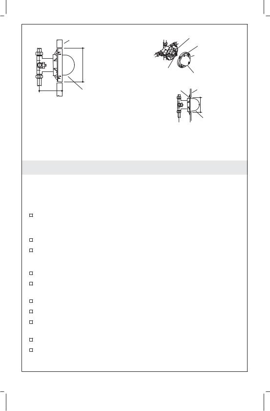
Finished Wall |
Backing Plate |
|
Outer Ring |
5-9/16" |
Plaster Guard |
|
|
(14.1 cm) D. |
|
Valve Stem |
Dome |
|
|
Backing Plate |
Wall Material |
Plaster Guard |
|
2-3/4" (7 cm) –
3-1/2" (8.9 cm) 4" (10.2 cm) D. Rough-In Depth

 Plaster Guard 2-3/4" (7 cm)
Rough-In Depth
Thick Wall |
Thin Wall |
6. Complete the Finished Wall
NOTE: Thick wall installations are typically tile, plaster, marble, or similar materials. Thin wall installations are typically fiberglass and acrylic.
Thick Wall Installation
Provide a 5-9/16″ (14.1 cm) diameter hole in the wall material. The flat front surface of the plaster guard must be flush with the finished wall.
Complete the finished wall.
Do not remove the plaster guard until instructed.
Thin Wall Installation
Remove the plaster guard from the backing plate.
Twist the plaster guard dome to separate it from the outer ring. Discard the outer ring.
Slide the dome over the valve stem.
Provide a 4″ (10.2 cm) diameter hole in the wall material.
Make openings for the stops (if included) by using the holes in the backing plate as a guide.
Secure the backing plate to the back of the wall material.
Do not remove the dome until instructed to do so.
Kohler Co. |
9 |
114811-2-CG |

Tab
Setscrew Collar
Valve
Label
Valve
Stem
O-Ring
7. Optional Temperature Limiting Adjustment
CAUTION: Risk of personal injury. The water temperature should never be set above 120° F (49° C).
Turn the valve clockwise to the full open position and let the hot water run for several minutes. Position a thermometer in the water stream and check the temperature.
For minor water temperature changes, adjust the setscrew, and recheck the water temperature.
For major water temperature changes, remove the O-ring and collar from the valve stem. Slowly rotate the valve stem until the desired maximum water temperature is reached.
Reinstall the collar on the valve stem with the setscrew against the side of the tab.
Reinstall the O-ring, rotate the valve stem counterclockwise to shut the water off.
Recheck the water temperature.
Complete the information on the valve label (if supplied).
114811-2-CG |
10 |
Kohler Co. |
 Loading...