


 Loading...


 8104934

© 2006 Piaggio & C. S.p.A. - Noale (VE)
First edition: December 2005
Reprint: June 2006
Produced and printed by:
VALLEY FORGE DECA
Ravenna, Modena, Torino
DECA S.r.l.
Registered & Admin. Offices Via Vincenzo Giardini, 11 48022 Lugo (RA) - Italia - Tel. 0545-216611
Fax 0545-216610 www.vftis.com deca@vftis.spx.com
on behalf of:
Piaggio & C. S.p.A.
via G. Galilei, 1 - 30033 Noale (VE) - Italia Tel. +39 - 041 58 29 111
Fax +39 - 041 44 10 54 www.aprilia.com
SAFETY WARNINGS
The following precautionary warnings are used throughout this manual in order to convey the following messages:
Safety warning. When you find this symbol on the vehicle or in the manual, be careful to the
potential risk of personal injury. Noncompliance with the indications given in the messages preceded by this symbol may result in grave risks for your and other people’s safety and for the vehicle!
Indications to make the operations easier. Technical
information.
 TECHNICAL INFORMATION
HThe operations preceded by this
symbol must be repeated also on the opposite side of the vehicle.
If not expressly indicated otherwise, for the reassembly of the units repeat the disassembly operations in reverse order.
The terms “right” and “left” are referred to the rider seated on the vehicle in the normal riding position.
WARNINGS - PRECAUTIONS - GENERAL ADVICE
Before starting the engine, carefully read this manual and in particular the section “SAFE DRIVE”.
Your and other people’s safety depends not only on your quickness of reflexes and on your agility, but also on what you know about the vehicle, on its efficiency and on your knowledge of the basic information for “SAFE DRIVE”.
Therefore, get a thorough knowledge of the vehicle, in such a way as to be able to drive in the traffic safely.
2 use and maintenance RS 125
This manual must be considered as an integral part of the vehicle and must always accompany it,
even in case of resale.
aprilia has carried out this manual with the maximum attention, in order to supply the user with correct and updated information. However, since aprilia constantly improves the design of its products, there may be slight discrepancies between the characteristics of your vehicle and those described in this manual.
For any clarification concerning the information contained in this manual, do not hesitate to contact your aprilia Official Dealer.
For control and repair operations not expressly described in this publication, for the purchase of aprilia genuine spare parts, accessories and other products, as well as for specific advice, contact exclusively aprilia Official Dealers and Service Centers, which guarantee prompt and accurate assistance.
Thank you for choosing aprilia. We wish you a nice ride.
All rights as to electronic storage, reproduction and total or partial adaptation, with any means, are reserved for all Countries.
In some countries the antipollution and noise regulations in force require periodical inspections.
The user of the vehicle in these countries must:
–contact an aprilia Official Dealer to have t he non - homologat ed components replaced with others homologated for use in the country in question;
–carry out the required periodical inspections.
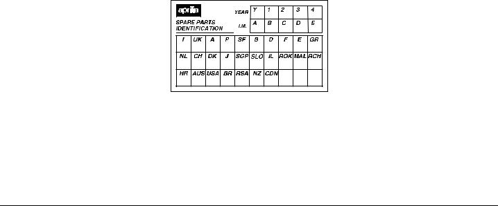
Soon after purchasing the vehicle, write down the identification data indicated on the SPARE PARTS IDENTIFICATION LABEL in the table here below. The label is positioned under the rider saddle, see page 56 (REMOVING
THE RIDER SADDLE).
These data indicate:
–YEAR = year of manufacture (Y, 1, 2, ...);
–I.M. = modification code (A, B, C, ...);
–COUNTRY CODES = homologation country (I, UK, A, ...).
and are to be supplied to the aprilia Official Dealer as reference data for the purchase of spare parts or specific accessories of the model you have acquired.
In this manual the various versions are indicated by the following symbols:
J optional
k Full Power version
L catalytic version
VERSION: |
|
|
+ Italy |
2 Singapore |
|
4 United Kingdom P Slovenia |
||
> Austria |
F Israel |
|
M Portugal |
e South Korea |
|
( Finland |
- Malaysia |
|
$ Belgium |
@ Chile |
|
A Germany |
* Croatia |
|
C France |
# Australia |
|
' Spain |
R United States |
|
of America |
||
|
||
) Greece |
g Brazil |
|
/ Holland |
1 South Africa |
|
6 Switzerland |
K New Zealand |
|
& Denmark |
% Canada |
|
, Japan |
|
|
use and maintenance RS 125 3

TABLE OF CONTENTS
SAFETY WARNINGS .......................................... |
2 |
TECHNICAL INFORMATION .............................. |
2 |
WARNINGS - PRECAUTIONS - GENERAL |
|
ADVICE ................................................................ |
2 |
BASIC SAFETY RULES ................................ |
6 |
CLOTHING .................................................... |
8 |
ACCESSORIES............................................. |
8 |
LOAD ............................................................. |
9 |
ARRANGEMENT OF THE MAIN ELEMENTS .. |
10 |
ARRANGEMENT OF THE |
|
INSTRUMENTS/CONTROLS ............................ |
12 |
INSTRUMENTS AND INDICATORS ................. |
13 |
INSTRUMENTS AND INDICATORS TABLE.... |
|
14 |
|
MULTIFUNCTION COMPUTER.................. |
16 |
MAIN INDEPENDENT CONTROLS .................. |
21 |
CONTROLS ON THE LEFT PART |
|
OF THE HANDLEBAR................................. |
21 |
CONTROLS ON THE RIGHT PART |
|
OF THE HANDLEBAR................................. |
21 |
IGNITION SWITCH...................................... |
22 |
STEERING LOCK........................................ |
22 |
AUXILIARY EQUIPMENT.................................. |
23 |
GLOVE/TOOL KIT COMPARTMENT.......... |
23 |
SPECIAL TOOLS J................................. |
24 |
MAIN COMPONENTS........................................ |
25 |
FUEL............................................................ |
25 |
TRANSMISSION OIL................................... |
25 |
BRAKE FLUID-recommendations ............... |
26 |
DISC BRAKES............................................. |
26 |
FRONT BRAKE ........................................... |
27 |
REAR BRAKE.............................................. |
28 |
2 STROKE OIL TANK.................................. |
29 |
ADJUSTING THE SHIFTING LEVER.......... |
29 |
ADJUSTING THE REAR BRAKE ................ |
30 |
ADJUSTING THE CLUTCH......................... |
30 |
COOLANT ................................................... |
32 |
TYRES ......................................................... |
33 |
CATALYTIC SILENCER............................... |
34 |
INSTRUCTIONS FOR USE ................................ |
34 |
PRELIMINARY CHECKING OPERATIONS 35 |
|
STARTING ................................................... |
36 |
DEPARTURE AND DRIVE........................... |
38 |
RUNNING-IN................................................ |
41 |
STOPPING................................................... |
41 |
PARKING ..................................................... |
42 |
SUGGESTIONS |
|
TO PREVENT THEFT.................................. |
42 |
MAINTENANCE.................................................. |
43 |
REGULAR SERVICE INTERVALS CHART. 44 |
|
IDENTIFICATION DATA .............................. |
46 |
POSITIONING THE VEHICLE ON THE REAR |
|
SUPPORT STAND J............................... |
47 |
POSITIONING THE VEHICLE ON THE |
|
FRONT SUPPORT STAND J.................. |
47 |
CHECKING THE TRANSMISSION OIL LEVEL |
|
AND TOPPING UP....................................... |
48 |
CHANGING THE TRANSMISSION OIL....... |
49 |
FRONT WHEEL ........................................... |
50 |
REAR WHEEL.............................................. |
52 |
DRIVE CHAIN .............................................. |
54 |
REMOVING THE RIDER SADDLE .............. |
56 |
REMOVING THE SIDE FAIRINGS .............. |
56 |
REMOVING THE LOWER FAIRING............ |
57 |
LIFTING THE FUEL TANK........................... |
57 |
AIR CLEANER ............................................. |
58 |
REAR SUSPENSION................................... |
59 |
CHECKING THE BRAKE PAD WEAR......... |
60 |
IDLING ADJUSTMENT ................................ |
61 |
ADJUSTING |
|
THE ACCELERATOR CONTROL................ |
62 |
ADJUSTING |
|
THE COLD START CONTROL ( )............. |
62 |
SPARK PLUGS ............................................ |
63 |
BATTERY..................................................... |
64 |
LONG INACTIVITY |
|
OF THE BATTERY ...................................... |
64 |
CHECKING AND CLEANING |
|
THE TERMINALS ........................................ |
65 |
REMOVING THE BATTERY........................ |
65 |
CHECKING |
|
THE ELECTROLYTE LEVEL....................... |
66 |
RECHARGING THE BATTERY................... |
66 |
INSTALLING THE BATTERY ...................... |
66 |
CHANGING THE FUSES ............................ |
67 |
CHECKING THE SWITCHES...................... |
68 |
VERTICAL ADJUSTMENT OF THE |
|
HEADLIGHT BEAM ..................................... |
69 |
BULBS ......................................................... |
69 |
CHANGING |
|
THE HEADLIGHT BULBS ........................... |
70 |
CHANGING |
|
THE REAR LIGHT BULB............................. |
71 |
TRANSPORT ..................................................... |
72 |
CLEANING......................................................... |
73 |
LONG PERIODS OF INACTIVITY............... |
74 |
TECHNICAL DATA............................................ |
75 |
LUBRICANT CHART ................................... |
78 |
Official Dealers and Service Centres........... |
80 |
4 use and maintenance RS 125
safe drive
BASIC SAFETY RULES
To drive the vehicle it is necessary to be in possession of all the requirements prescribed by law (driving licence, minimum age, psychophysical ability, insurance, state taxes, vehicle registration, number plate, etc.).
Gradually get to know the vehicle by driving it first in areas with low traffic and/or private areas.
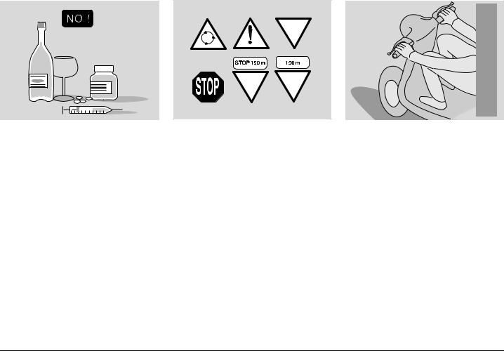
The use of medicins, alcohol and drugs or psychotropic substances notably increases the risk of accidents.
Be sure that you are in good psychophysical conditions and fit for driving and pay particular attention to physical weariness and drowsiness.
Most road accidents are caused by the driver’s lack of experience.
NEVER lend the vehicle to beginners and, in any case, make sure that the driver has all the requirements for driving.
Rigorously observe all road signs and national and local road regulations.
Avoid abrupt movements that can be dangerous for yourself and other people (for example: rearing up on the back wheel, speeding, etc.), and give due consideration to the road surface, visibility and other driving conditions.
Avoid obstacles that could damage the vehicle or make you lose control.
Avoid riding in the slipstreamcreated by preceding vehicles in
order to increase your speed. Always drive with both hands on the handlebars and both feet on the footrests (or on the rider’s footboards), in the correct driving posture.
Avoid standing up or stretching your limbs while driving.
6 use and maintenance RS 125
ONLY ORIGINALS
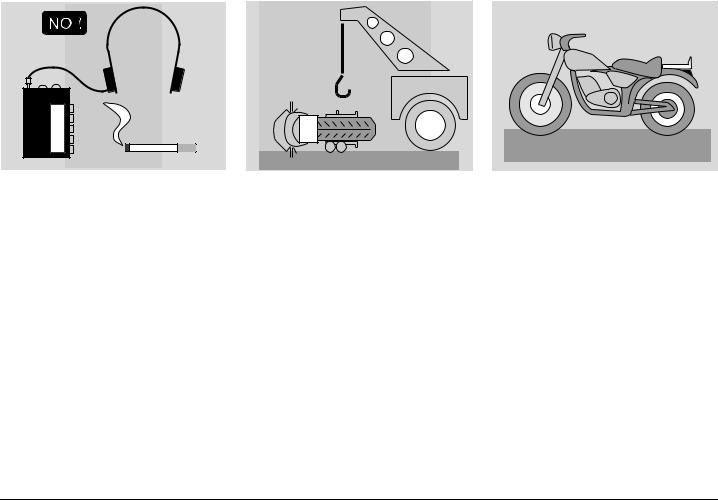
The driver should pay attention and avoid distractions caused by people, things and movements (never smoke, eat, drink, read, etc.) while driving.
Use only the vehicle’s specific fuels and lubricants indicated in the "LUBRICANT CHART"; check the oil, fuel and coolant levels regularly.
If the vehicle has been involved in an accident, make sure that no damage has occurred to the control levers, pipes, wires, braking system and vital parts.
If necessary, have the vehicle inspected by an aprilia Official Dealer, who should carefully check the frame, handlebars, suspensions, safety parts and all the devices that you cannot check by yourself.
Always remember to report any malfunction to the technicians to help them in their work.
Never use the vehicle when the amount of damage it has suffered endangers your safety.
Never change the position, inclination or colour of: number plate, direction indicators, lights and horns.
Any modification of the vehicle will result in the invalidity of the guarantee.
Any modification of the vehicle and/or the removal of original components can compromise vehicle performance levels and safety or even make it illegal.
We recommend respecting all regulations and national and local provisions regarding the equipment of the vehicle.
In particular, avoid all modifications that increase the vehicle’s performance levels or alter its original characteristics.
Never race with other vehicles.
Avoid off-road driving.
use and maintenance RS 125 7
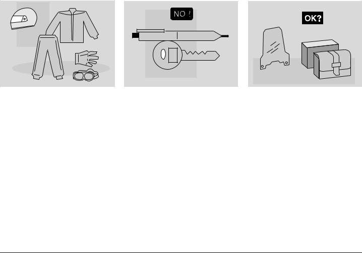
CLOTHING |
Before starting, always wear a correctly fastened crash helmet. Make sure that it is homologated, in good shape, of the right size and that the visor is clean.
Wear protective clothing, preferably in light and/or reflecting colours. In this way you will make yourself more visible to the other drivers, thus notably reducing the risk of being knocked down, and you will be more protected in case of fall.
This clothing should be very tight-fitting and fastened at the wrists and ankles. Strings, belts and ties should not be hanging loose; prevent these and other objects from interfering with driving by getting entangled with moving parts or driving mechanisms.
Do not keep objects that can be dangerous in case of fall, for example pointed objects like keys, pens, glass vials etc. in your pockets (the same recommendations also apply to passengers).
ACCESSORIES |
The owner of the vehicle is responsible for the choice, installation and use of any accessory.
Avoid installing accessories that cover horns or lights or that could impair their functions, limit the suspension stroke and the steering angle, hamper the operation of the controls and reduce the distance from the ground and the angle of inclination in turns.
Avoid using accessories that hamper access to the controls, since this can prolong reaction times during an emergency.
Large fairings and windscreens assembled on the vehicle can produce aerodynamic forces capable of compromising the stability of the vehicle while driving.
8 use and maintenance RS 125
Make sure that the equipment is well fastened to the vehicle and not dangerous during driving. Do not install electrical devices and do not modify those already existing to avoid electrical overloads, because the vehicle could suddenly stop or there could be a dangerous current shortage in the horn and in the lights. aprilia recommends the use of genuine accessories ( aprilia genuine accessories).
LOAD
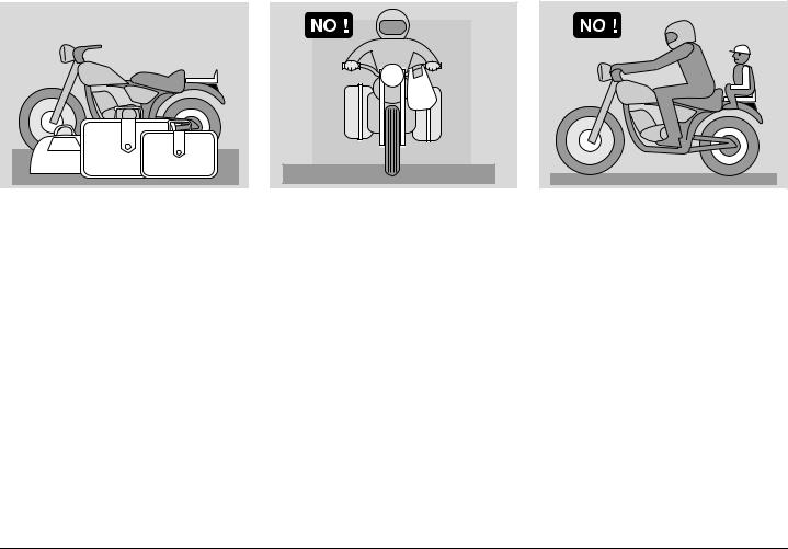
Be careful and moderate when loading your luggage. Keep any luggage loaded as close as possible to the centre of the vehicle and distribute the load uniformly on both sides, in order to reduce imbalance to the minimum. Furthermore, make sure that the load is firmly secured to the vehicle, especially during long trips.
Avoid hanging bulky, heavy and/or dangerous objects on the handlebars, mudguards and forks, because the vehicle might respond more slowly in turns and its manoeuvrability could be unavoidably impaired.
Do not place bags that are too bulky on the vehicle sides and do not ride with the crash helmet hanging from its string, because it could hit people or obstacles making you lose control of the vehicle.
Do not carry any bag if it is not tightly secured to the vehicle.
Do not carry bags which protrude too much from the luggage rack or which cover the lights, horn or indicators.
Do not carry animals or children on the glove compartment or on the luggage rack.
Do not exceed the maximum load allowed for each side-bag.
When the vehicle is overloaded, its stability and its manoeuvrability can be compromised.
use and maintenance RS 125 9

ARRANGEMENT OF THE MAIN ELEMENTS
KEY
1)Dashboard
2)Left rear-view mirror
3)Ignition switch/steering lock
4)Battery
5)Fuse carrier
6)Saddle lock
1 |
2 |
3 |
4 |
5 |
6 |
7 |
8 |
9 |
10 |
16 |
15 |
14 |
13 |
12 |
11 |
7) |
2 stroke oil tank |
11) |
Rider left footrest |
8) |
2 stroke oil tank plug |
|
(with spring, always open) |
9) |
Glove/tool kit compartment |
12) |
Shifting lever |
10) |
Passenger left footrest |
13) |
Side stand |
|
(snapping, closed/open) |
14) |
Lower fairing |
|
|
15) |
Horn |
|
|
16) |
Left side fairing |
10 use and maintenance RS 125
1 |
2 |
3 |
4 |
5 |
6 |
7 |
8 |
9 |
10 |
KEY
1)Passenger right footrest (snapping, closed/open)
2)Passenger grab strap
3)Rider saddle
4)Air cleaner
5)Rear brake fluid tank
14 |
13 |
12 |
11 |
6)Fuel tank plug
7)Coolant expansion tank plug
8)Expansion tank
9)Right rear-view mirror
10)Front brake fluid tank
11)Rear brake pump
12)Rear brake control lever
13)Rider right footrest
(with spring, always open)
14)Drive chain
use and maintenance RS 125 11
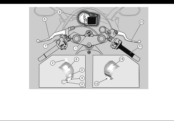
ARRANGEMENT OF THE INSTRUMENTS/CONTROLS
KEY |
|
|
|
1) |
Ignition switch/steering lock ( - - +) |
8) |
Clutch lever |
2) |
Cold start lever ( ) |
9) |
Instruments and indicators |
3) |
Direction indicator switch ( () |
10) |
Front brake lever |
4) |
Horn push button ( ) |
11) |
Throttle grip |
5) |
MODEpush button |
12) |
Start push button ( ) |
6) |
Dimmer switch ( - ) |
13) |
Engine stop switch ( - ) |
7) |
High beam signalling push button ( ) |
|
|
12 use and maintenance RS 125
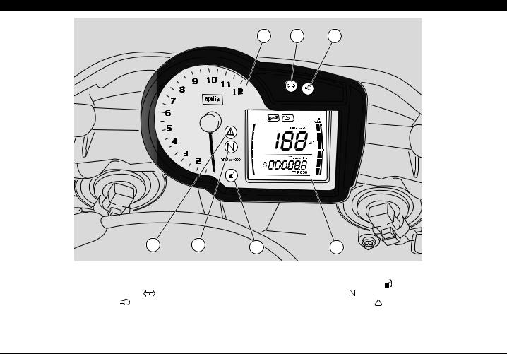
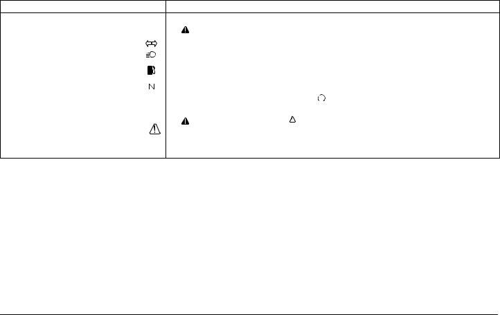
INSTRUMENTS AND INDICATORS
1 |
2 |
3 |
7 |
6 |
5 |
4 |
KEY |
|
|
|
|
|
1) |
Revolution counter |
|
5) |
Amber low fuel warning light ( |
) |
2) |
Green turn indicator warning light ( |
) |
6) |
Green neutral light ( ) |
|
3) |
lue high beam warning light ( ) |
|
7) |
Red general warning light ( |
) |
4)Multifunction digital display (coolant temperature - clock - battery voltage - lap timer - mixer oil level diagnostics ( )
)
use and maintenance RS 125 13
INSTRUMENTS AND INDICATORS TABLE
When the ignition key is turned to " " with the engine stopped, all warning lights come on for a LED check-up and go out after two seconds. If one or more warning lights do not come on at this stage, contact an aprilia Official Dealer
Description |
Function |
Indicates the number of revolutions of the engine per minute.
Revolution counter rpm |
|
|
|
|
|
Never exceed the engine max. speed rate, see page 41 (RUNNING-IN). |
|
|
|
|
|
CAUTION |
|||
|
|
|
|
|
|||
|
|
|
|
|
|
|
|
Direction indicator warning light |
|
|
|
Blinks when the direction indicators are on. |
|||
|
|
|
|
|
|
||
High beam warning light |
|
|
|
Comes on when the high beam bulbs are on or when the headlight signaller is operated. |
|||
|
|
|
|
|
|
||
Low fuel warning light |
|
|
|
It comes on when the quantity of fuel left in the tank is approx. 3.5 b. |
|||
|
|
|
|||||
|
|
|
In this case, top up as soon as possible, see page 25 (FUEL). |
||||
|
|
|
|
||||
|
|
|
|
|
|
|
|
Neutral indicator warning light |
|
|
|
Comes on when the gear is in neutral. |
|
||
|
|
|
|
|
|
||
|
|
|
|
Comes on when the ignition switch is set to " " with the engine stopped as a lamp test. |
|||
|
|
|
|
If the light does not come on in this phase, contact an aprilia Official Dealer. |
|||
|
|
|
|
|
|
If the light |
remains on after the engine starts or comes on during |
Error warning light |
|
|
|
|
CAUTION |
||
|
|
|
|
the normal operation of the engine, this means that low fluid level in |
|||
|
|
|
|
|
|||
|
|
|
|
tank and mixer or high coolant temperature was detected. |
|||
|
|
|
|
In this case, check and/or top up to recommended fluid level and contact an aprilia Authorised |
|||
|
|
|
|
dealer, if necessary. |
|
|
|
14 use and maintenance RS 125

Description |
|
Function |
|
|
|
|
||
|
Speedometer (km/h - MPH) |
Displays current, average or maximum riding speed (in kilometres or miles) |
|
|
||||
|
depending on pre-setting, see page 16 (MULTIFUNCTION COMPUTER). |
|
|
|||||
|
|
|
|
|
||||
|
|
|
|
|
|
|
||
|
Odometer (KM - Mi) |
Gives total distance covered or distance covered since the trip meter was last reset |
|
|
||||
|
(in km or miles). |
|
|
|
|
|||
|
|
|
|
|
|
|
||
|
|
|
|
|
|
|
||
|
|
|
It reproduces engine coolant temperature on a scale, see page 16 |
|
|
|||
|
|
|
(MULTIFUNCTION COMPUTER). |
|
|
|
||
|
|
|
If you enter the dangerous range, the display shows all six scale segments, the |
|
|
|||
|
|
|
alarm light comes on, and logo |
flashes; allow the cooling fans to switch off. |
|
|
||
|
|
|
|
|
Do not leave the ignition switch on “ ”, since the |
|
|
|
|
|
|
|
CAUTION |
|
|
||
|
Coolant temperature |
|
cooling fans would stop regardless of the coolant |
|
|
|||
|
|
|
|
|
||||
|
(°C/°F) |
|
temperature and in this case the temperature would increase even further. |
To |
toggle be - |
|||
|
|
|
Now turn the key to “ |
” and check coolant level, see page 32 (COOLANT). |
||||
|
|
|
tween readouts, |
|||||
Multifunction |
|
|
Contact an aprilia Official Dealer. |
|||||
|
|
|
|
If the maximum allowed temperature is exceeded |
see |
page 16 |
||
digital display |
|
|
|
CAUTION |
(MULTIFUNC - |
|||
|
|
|
damaged. |
(114 °C - 237 °F), the engine may be seriously |
TION COMPU- |
|||
|
|
|
|
|
TER) |
|||
|
Mixer oil |
reserve |
It comes on when the quantity of mixer oil left in the tank is 0.60 b. |
|
|
|||
|
|
|
If oil reserve indicator comes on, this means that |
|
|
|||
|
indicator |
on |
|
CAUTION |
|
|
||
|
multifunction display |
|
|
mixer oil level is low (reserve); top up mixer oil, see |
|
|
||
|
page 29 (2 STROKE OIL TANK). |
|
|
|
||||
|
|
|
|
|
|
|||
|
|
|
|
|
|
|
||
|
Clock |
|
Displays time (hour and minutes) as preset, see page 16 (MULTIFUNCTION |
|
|
|||
|
|
COMPUTER). |
|
|
|
|
||
|
|
|
|
|
|
|
||
|
|
|
|
|
|
|
||
|
Battery voltage |
Displays the battery voltage in Volts, see page 16 (MULTIFUNCTION |
|
|
||||
|
COMPUTER). |
|
|
|
|
|||
|
|
|
|
|
|
|
||
|
|
|
|
|
|
|
||
|
Lap timer |
|
Displays the different lap times, as preset, see page 16 (MULTIFUNCTION |
|
|
|||
|
|
COMPUTER). |
|
|
|
|
||
|
|
|
|
|
|
|
||
|
|
|
|
|
|
|
|
|
use and maintenance RS 125 15
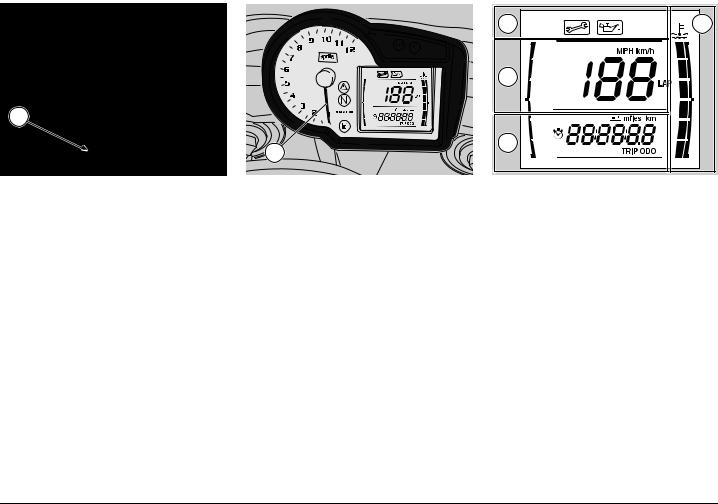
1
2 |
MULTIFUNCTION COMPUTER
Controls
1) MODE Button:
press briefly to switch across functions;
press for several seconds (more than three seconds) to change settings.
When you turn the ignition key to "  ", the following instrument panel lights will turn on for two seconds:
–all warning lights;
–backlighting;
–All segments on the display come on. The rev counter index (2) gets to scale end and goes back to starting position.
A |
D |
B |
|
C |
|
During the initial check-up, all instruments will briefly show the current values of the corresponding parameters. The following standard settings are displayed:
–Alarm icons, (zone A);
–Current speed (zone B)
–Odometer / trip meter / time / battery voltage / lap timer (zone C) (*);
–Coolant temperature (zone D).
(*) The function displayed the last time the key was turned off is the one displayed first.
16 use and maintenance RS 125
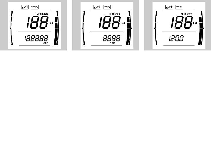
Description of the functions
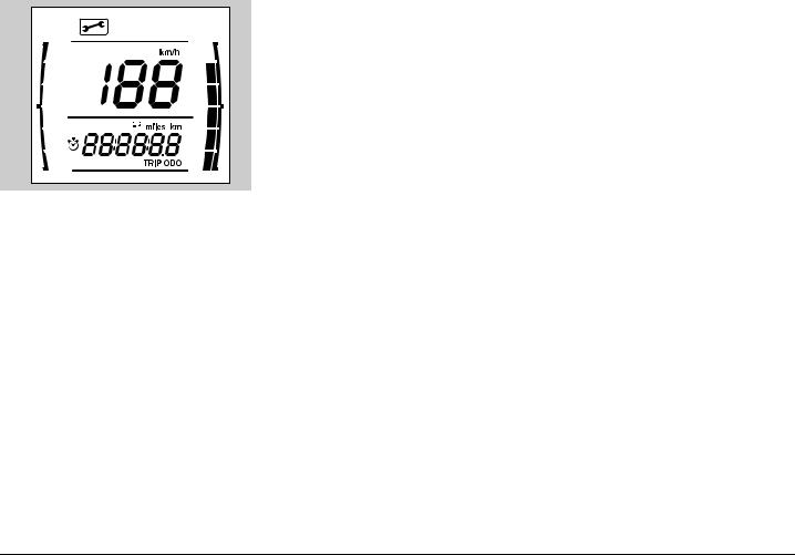
Press the MODE button a few times and the following functions are alternatively displayed in area C of the display:
–ODOMETER (ODO)
–TRIP METER (TRIP)
–CLOCK
–BATTERY VOLTAGE
–LAP TIMER
ODOMETER (ODO)
Displayed value indicates total distance covered by the vehicle.
It can not be reset.
TRIP METER (TRIP)
With the ODO function displayed briefly press the MODE button to display trip meter value.
With the TRIP value displayed, press and hold the MODE button to reset it.
CLOCK
With the TRIP value displayed, briefly press the MODE button to display the time.
Setting the time
With vehicle stopped and time displayed, press the MODE button for several seconds to activate time setting mode. The display will show the two digits indicating hour; every time you press the MODE button, the value increases by one; if you press the MODE button when hour value is 12, the indication will go back to 1.
Press the MODE button for several seconds to save the value and start setting minutes, the display will only show minute digits; every time you press the MODE button, the value increases by one, if you press the MODE button when value is 59, the indication will go back to 0.
use and maintenance RS 125 17
Do not disturb any button for three seconds to complete the procedure and the display will show set time.
LAP TIMER
With the Clock function displayed, briefly press the MODE button to display Lap timer function. Press the MODE button for several seconds with the vehicle running to enter the time acquisition mode, or press it with the vehicle stopped to enter the lap time display mode.
Timing
With the vehicle running, briefly press the MODE button to start the lap timer. Press it once to start the timer, press it further within the first ten seconds to reset the lap timer. If you press it again after 10 seconds have elapsed since timer start, value is stored and timer for next lap starts. The value stored is displayed for the first 10 seconds, then the current value is shown.
Press the MODE button for several seconds to abort timing, the display will show the last value stored; timing session restarts as previously indicated.
As soon as 16 lap times have been stored, the display reads FULL, any new lap times will not be stored.
Detaching the battery will result in loss of any data stored.
18 use and maintenance RS 125
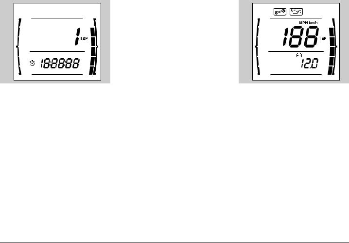
View times
Entering the Lap timer function with vehicle stopped lets you view the times stored.
The central area of the display, usually dedicated to current speed, shows LAP session number and the lap time just below.
Restart the vehicle or hold the MODE button for several seconds to quit view time mode.
Delete times
With the ODO function displayed, press the MODE button for several seconds to delete all lap times stored.
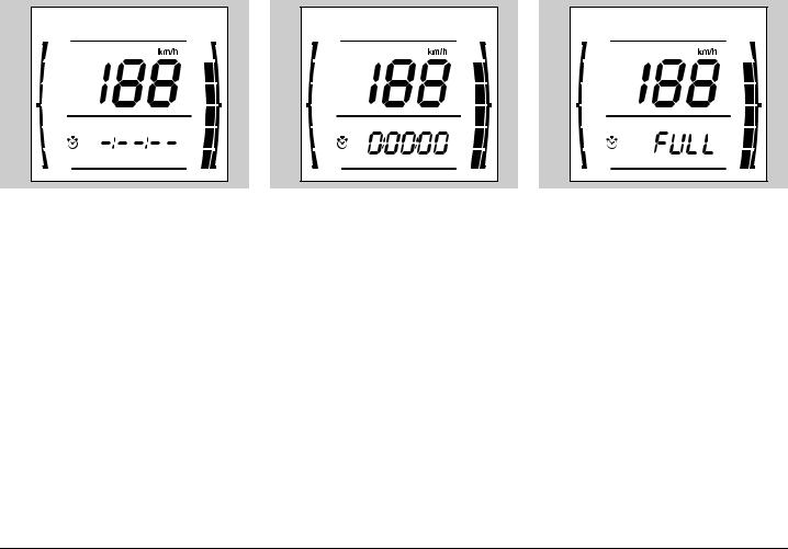
BATTERY VOLTAGE
With the Clock function displayed, briefly press the MODE button to display the battery icon and battery charge.
If the system detects a faulty voltage (not between 10 and 16 Volt) the symbol " " is displayed and flashes.
use and maintenance RS 125 19
Service interval
As the scheduled service interval is getting closer the display will show the wrench icon flashing for five seconds.
When scheduled service mileage is reached , the icon will stay on permanently.
First switch-on at 1,000 km (625 mi)
Then: every 4000 km (1,700 mi)
Have the scheduled service operations performed by aprilia Authorised Dealers and Service Centres, so that they will also delete the service warning.
Km/miles
When battery is connected, with key to "  ", hold the MODE button for more than ten seconds to switch both the odometer (ODO) an d the tachometer from kilometres (km) to miles (mi).
During the first fi ve se conds the instrument panel will not react with any signal , bu t then cu rren t un it o f measurement will start flashing. If MODE button is released before ten seconds have elapsed, the unit of measurement will still be the one previously in use.
20 use and maintenance RS 125
MAIN INDEPENDENT CONTROLS
6
5 |
4 |
3 |
3) DIMMER SWITCH ( - )
When it is in position “ ” the parking lights, the dashboard light and the low beam are always on.
When it is in position “ ”, the high beam comes on.
4) MODE BUTTON
Allows you to use the multifunction computer.
For the setting of the functions, see page 16 (MULTIFUNCTION
COMPUTER).
1 |
5) COLD START LEVER ( ) |
2 |
|
|
The starter for the cold start of the |
CONTROLS ON THE LEFT PART |
engine is operated by rotating the lever |
" " downwards. |
|
OF THE HANDLEBAR |
To disconnect the starter, move the |
The electrical parts work only |
lever " " to its initial position. |
when the ignition switch is in |
6) HIGH BEAM SIGNALLING PUSH |
position " ". |
BUTTON ( ) |
1) HORN PUSH BUTTON ( ) |
It makes it possible to use the high |
The horn is activated when the push |
beam for signalling to forthcoming |
button is pressed. |
vehicles while overtaking and in case of |
2) DIRECTION INDICATOR SWITCH |
peril and/or emergency. |
|
|
( () |
CONTROLS ON THE RIGHT PART |
To indicate the turn to the left, move the |
OF THE HANDLEBAR |
switch to the left; to indicate the turn to |
|
the right, move the switch to the right. |
The electrical parts work only |
To turn off the direction indicator, press |
when the ignition switch is in |
the switch. |
position " ". |
|
7) ENGINE STOP SWITCH ( - ) |
|
|
|
Do not operate the engine |
|
stop switch “ - ” in |
|
running conditions. |
7 |
8 |
This is a safety or emergency switch. With the switch in position " ", it is possible to start the engine; the engine can be stopped by moving the switch to position " ".
With stopped engine and ignition switch in position " ", the battery may discharge.
When the vehicle has come to rest, after stopping the engine, move the ignition switch to position " ".
8)START PUSH BUTTON ( )
When the start push button " " is pressed, the starter makes the engine run. For the starting, see page 36 (STARTING).
use and maintenance RS 125 21
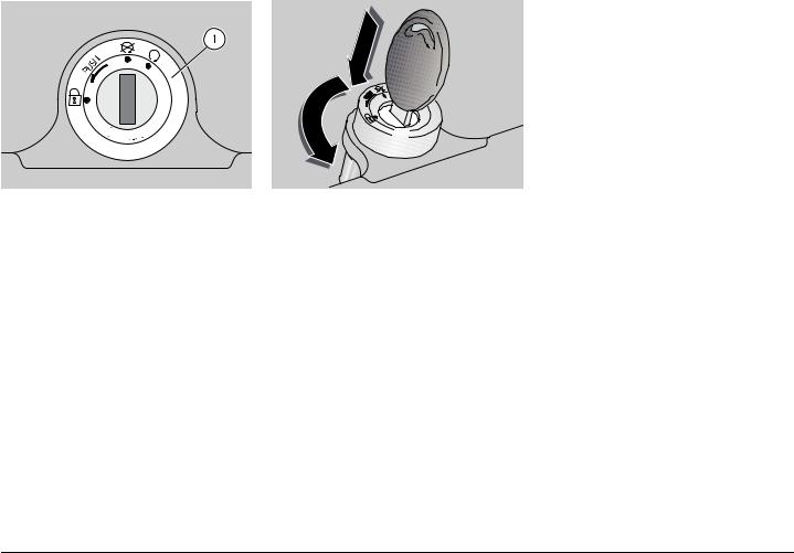
IGNITION SWITCH
The ignition switch (1) is positioned on the upper plate of the steering column.
The key operates the ignition switch/steering lock, the saddle
lock and the fuel tank lock.
Two keys are supplied together with the vehicle (one spare key).
STEERING LOCK
Never turn the key to position "+" in running conditions, in order to avoid losing control of
the vehicle.
OPERATION
To lock the steering:
uTurn the handlebar completely leftwards.
uTurn the key to position " ".
uPress the key and rotate it to position "+".
uExtract the key.
Position |
Function |
Key |
|
removal |
|||
|
|
||
|
|
|
|
+ |
The steering |
It is possible |
|
is locked. It |
to remove |
||
is not |
the key. |
||
Steering |
possible to |
|
|
start the |
|
||
lock |
|
||
engine. |
|
||
|
|
||
|
|
|
|
|
The engine |
It is possible |
|
cannot be |
to remove |
||
|
started. |
the key. |
|
|
|
|
|
|
The engine |
It is not |
|
can be |
possible to |
||
started. |
remove the |
||
|
|
key. |
|
|
|
|
22 use and maintenance RS 125
AUXILIARY EQUIPMENT
4 |
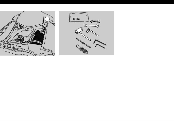
GLOVE/TOOL KIT COMPARTMENT
The glove/tool kit compartment is positioned under the rider saddle; to reach it:
uPosition the vehicle on the stand.
uRemove the rider saddle, see page 56 (REMOVING THE RIDER SADDLE).
uRemove the plastic panel.
The tool kit (4) includes:
–3, 5 mm Allen spanners
–10-13 mm double fork spanner
–8-mm fork spanner
–17-21 mm spark plug socket spanner
–Double-ended, cross-/4 mm hexagon spanner-headed screwdriver.
–Special socket wrench to adjust clutch play.
–Tool case
Max. allowed weight: 1.5 kg
use and maintenance RS 125 23
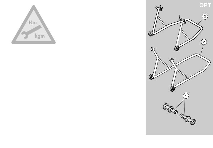
Tool |
Operations |
Page |
|
|
|
|
|||
Rear support |
Rear wheel disassembly. |
52 |
|
|
stand (2) |
Drive chain adjustment. |
54 |
|
|
|
|
|
|
|
Front support |
Front wheel disassembly. |
50 |
|
|
stand (3) |
|
|
|
|
|
|
|
|
|
|
|
|
|
|
Rear support |
Positioning of the vehicle |
|
|
|
stand coupling |
on the rear stand. |
47 |
|
|
pins (4) |
|
|
|
|
|
|
|
|
|
SPECIAL TOOLS J
To perform some specific operations, it is advisable to use the following special tools (to be requested to an aprilia Official Dealer):
24 use and maintenance RS 125
Loading...