


Moto 6.5 1996
Motó 6.5
MOTO'
6
5
use and maintenance
aprilia
part#
8102710

© 1996 aprilia s.p. a. - Noal e (VE)
This man ual is to be c onsider ed an int egral par t of the vehicle ,
which must be de li vered complete w ith it also in case of r esale.
aprilia s.p.a. reserves the right to modify its models at any
time, without prejudice to the main characteristics here de-
scribed.
All rig hts as to el ectr onic s torage, rep roduc tion and tot al or p ar-
tial adaptation, with any means, are reserved for all Countries.
The mention t o products or ser vices supp lied by th ird partie s is
made only for information purpos es and it isn’t bind ing in any
case.
aprilia s.p.a. takes no responsi bility as to the performa nce or
the use of sai d pr oducts.
First edition: January 19 96
Reprint
Produced and printed by
6WXGLR 7HFQR 3XEOLF
Viale del Progresso - 37038 Soave (VR) - Italia
Tel. 045 - 76 11 911
Fax 045 - 76 12 241
on behalf of
DSULOLD
s.p.a.
via G. Galilei, 1 - 30033 Noale (VE) - Italia
Tel. 041 - 58 29 111
Fax 041 - 44 10 54
2
,1752'8&7,21
Before starting the engine, carefully read this manual, paying
particular at t ent ion to the chapt er "S AF E DRIVE".
Your and other peopl e’s saf ety de pends not only on yo ur qui ck-
ness of r efl exes an d o n y our agil ity, but a ls o on w hat you know
about the vehicle, on its efficiency and on your knowledge of
the basic inf or m ation for SAFE DRIVE.
Therefore, get a thorough knowledge of the vehicle, in such a
way as to be able to drive in the traffic safely.
For the co ntrol s and r epai rs no t expres sl y descr ibed i n this m a-
nual, for the purchase of aprilia original spare parts, acces-
sories and other products, as well as for specific technical
advice, contact only aprilia Authorized Outlets and Official
Dealers, who can ensure you reli able and prompt servicing.
Thank you for choosing aprilia. We wish you a nice ride.
Carefully observe the instructions preceded by the following
warning signs:
Safety norms and regulations to protect the driver
and other people from severe injuries or grave
risks.
Caution norms and sug gest i ons to avoid damaging
the vehicle and/or hu rtin g your sel f or ot her people.
Indications to make the operations easier. Techni-
cal information.
IMPORTANT:
When aski ng your Deal er f or spare par ts, specify t he spare par t
code indicated on the SPARE PARTS IDENTIFICATION
LABEL.
Write down t he identifica tion code in the spa ce here below, i n
order to rem ember i t also i n ca se of loss or det erior ation of the
sticker.
The sticke r is placed un der the saddl e, on the left tube of the
pillar.
aprilia
CODICE RICAMBI spare parts code number
N° ABCDE
IUKSA PSFBD
F E GR NL CH DK N IRL
JSGP
3

*(1(5$/ &217(176
SAFE DRIVE............... ................ ............................ ................ ................. 5
BASIC SAFET Y R UL ES ................... .... .... ................ .... ................ .... .6
CLOTH ING.... .... .... .... ................ .... ................ ................ ................ ..... 9
ACCESSOR IES ................ .... .... .... ................ ................ ................ ...1 0
LOAD.................. ................ .... ................ ................ ................ ..........10
ARRANGEMENT OF THE MAIN ELEMENTS......................................12
ARRANGEMENT OF THE INSTRUMENTS..........................................14
INSTRUMENTS AND IN DIC A TOR S .......... .... ............................ ...........14
INSTRU M ENT A ND IN D IC A TO R TABLE .................... ................ ...1 5
MAIN INDEPENDENT CONTROLS ......................................................16
CONTROLS ON THE LEFT SIDE OF THE HANDLEBAR..............16
CONTROL S O N THE R I GH T SI DE O F THE HA NDL EBAR ...........1 7
IGNIT ION SW IT CH ........................... ................ .... ................ ...........18
STEERING LOCK................. ................ .... ................ ................ ....... 1 8
AUXILIARY EQUIPMENT......................................................................18
TOOL KIT.. ................ ................ ................ .... ................ ................ ...1 8
CRASH HEL M ET HOO K .................. .... ................ .... ................ ....... 1 9
MAIN COMPONENTS ...........................................................................19
FUEL ................................................................................................19
ENGINE O IL.......... ................ ................ .... ................ ................ ....... 2 0
BRAKE FLUI D (REC OM M E ND AT IO N S)) .................... ................ ...2 0
FRONT BRAKE................. ................ ................ .... ................ ...........21
REAR BRAKE..................................................................................22
CLUTCH...........................................................................................23
COOLANT........................................................................................24
CATALYTIC SILEN CERS..................... ................ ................ .... ....... 2 5
TYRES .. ................ ................ .... ................ ................ .... ................ ...2 6
INSTRUCTIONS FOR USE ...................................................................27
PRELIMINARY CHECKING OPERATIONS TABLE .......................27
STARTING .......................................................................................28
DEPART UR E AND DRIVE ... .... ................ ................ .... ................ ...3 0
RUNNING-IN. .... ................ .... ................ ................ .... ................ ....... 3 2
STOPPING AND PARKING.............................................................33
SUGGESTI O NS TO PRE VEN T THEF T ........... .... .... ................ .... ...3 3
MAINTENANCE.............. .... .... ................ ................ ................ ...............3 4
PERIODI C M AINTENANCE CHART................ .... .... .... .... ...............3 5
IDENTIFICATION DATA..................................................................36
CHECKI NG TH E ENG I NE O IL LE VEL A ND TO PP ING UP. .... .... ...3 6
CHANGING THE ENGINE OIL AND THE OIL FILTER .................. 37
FRONT WHEEL...............................................................................38
REAR WH EEL ..................... ................ .... ................ ................ ........39
CHAIN.. .... .... .... .... ................ .... ................ ................ .... ................ .... 40
REMOVING THE FUEL TANK ........................................................42
AIR FIL TER ......... .... .... .... .... ................ .... ................ ................ ........42
FRONT AND REAR SUSPENSION INSPECTION......................... 43
ADJUST ING THE REAR SUSPEN S ION ............ .... .... .... .... ............ 43
CHECK ING THE STEERIN G ...... .... .... .... .... ................ ................ .... 44
LOCK ING / UN L OC K ING THE SADDLE .................. .... ................ .... 45
REMOVING THE SIDES .................................................................45
IDLING ADJUSTMENT....................................................................46
TAKING U P THE THROTTL E G RIP SLACK .......... .... ................ .... 46
CHECKING THE BRAKE PAD WEAR ............................................46
SPARK PLUG.................................................................................. 47
BATTERY ........................................................................................ 48
LONG PER IO D O F IN AC T IVI TY. .... .... .... ................ .... .... ................ 49
CHANGI N G TH E FU SES .... .... .... .... .... ................ ................ .... ........49
CHECKING THE SIDE STAND SWITCH........................................50
ADJUST ING THE HEADLI GH T BEA M ....... ................ .... ................ 50
BULBS ..... .... ................ ................ ................ ................ ................ .... 51
CHANGI N G THE HEADLIGHT BULBS ... .... .... .... ................ .... ........51
CHANGI N G THE REAR LIGH T BULB S... ................ .... .... ............... 52
CHANGI N G THE NUMBER PL AT E BUL B ... .... .... .... .... ................ ... 53
CHANGI NG THE TURN INDICATOR BULBS ........ .... ................ .... 53
CHANGI N G THE DASHBOA RD BU L BS ................ .... .... ................ 53
TRANSPORT. .... ................ ................ ................ ................ .... ................ 54
EMPTY ING TH E FU EL TAN K............. .... ................ ................ ........54
CLEANING ............ .... .... .... ................ ................ .... ................ ................ 54
LONG PERIODS OF INACTIVITY ..................................................55
AFTER A LON G PERIOD OF IN ACTIVITY ................ .... ................ 55
TECHNICAL DATA ........................................... ............................ ........56
WIRING DIAGRAM .. .... ................ .... ................ ................ ................ 59
WIRING DIAGRAM KEY ................. .... ................ .... ................ ........60
LUBRICANT CHART.......................................................................61
IMPORTERS ................................................................................... 62
4
safe drive
To drive the vehicle it is necessary to
have all the r equir emen ts pro vided for in
law (driving licence, minimum age re-
quired, psychophysical ability, insurance,
state taxes, registration, number plate,
etc.).
Gradually get to know the vehicle, driv-
ing it in areas with low traffic and/or in
priva t e areas.
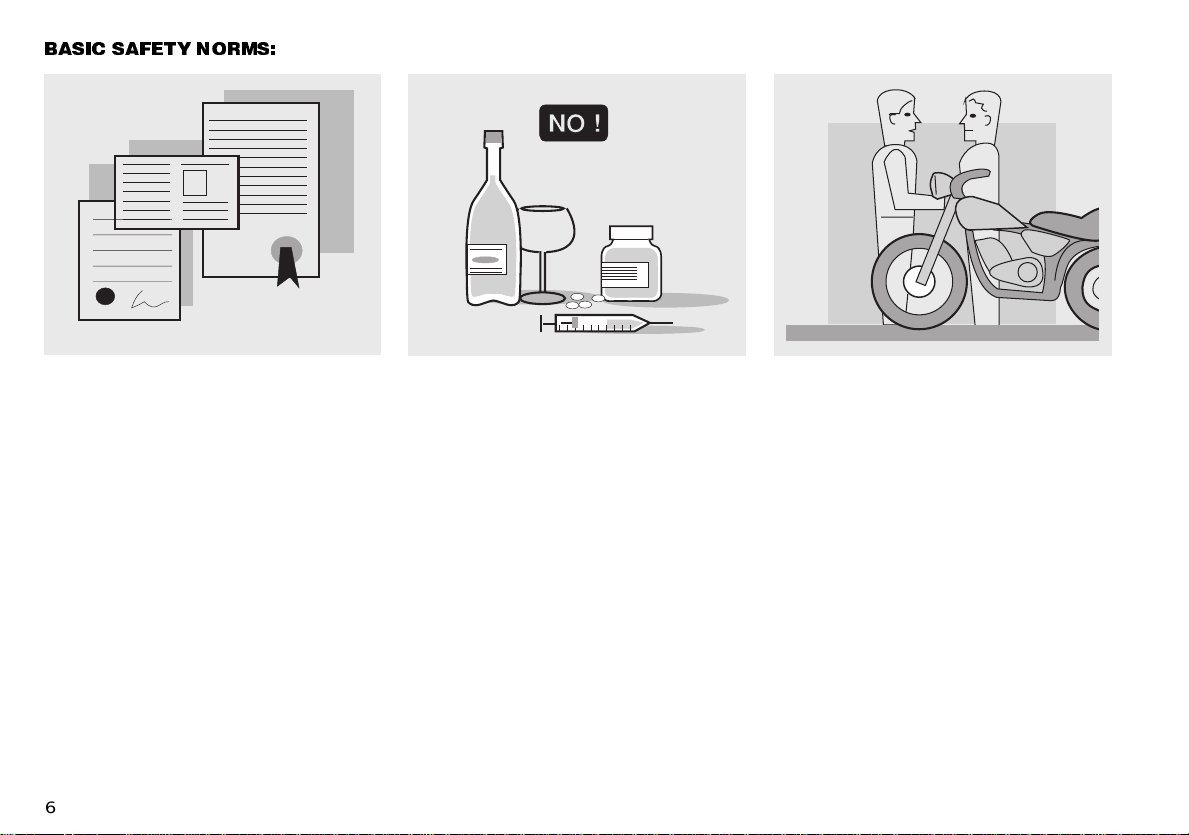
The taking of some medicinal prepara-
tions , alcoho l an d drugs or psyc ho trop ic
substances notably increases the risk of
acci dents .
Be sure that you are in good psycho-
physical conditions, fit for driving, paying
particular attention to physical weariness
and drowsiness.
Most road accidents are ascribable to
the dr i ver’s l ack of experie nce.
NEVER lend the vehicle to beginners
and, in any case, be sure that the driver
has all the requirements necessary for
driving.
%$6,& 6$)(7< 12506
6
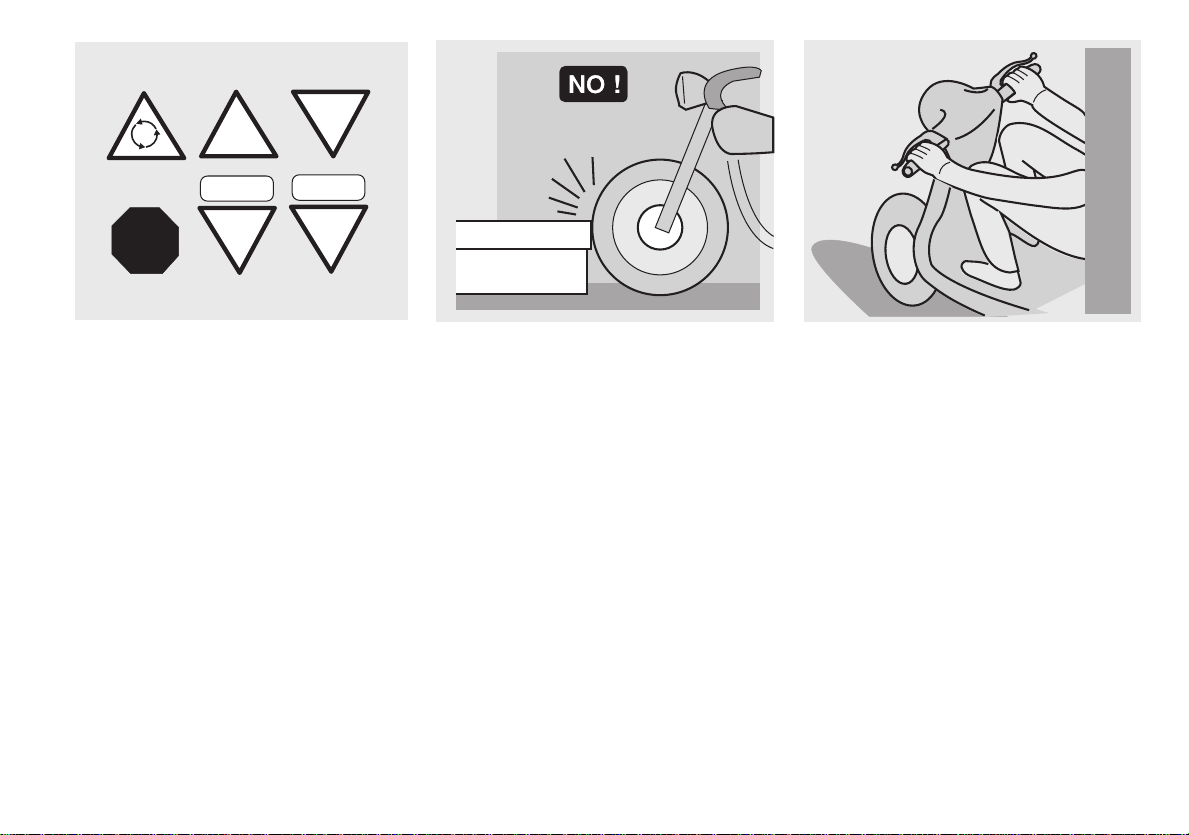
Rigorously observe the road signs and
the national and local road regulations.
Avoid any abrupt movement, which can
be dangerous for yourself and for other
people (for example: rearing up, speed
limit excess , etc .), a nd ver ify and a lways
take i nto consider ation the roa d surface
conditions, visibility etc.
Do not hit obst acles which co uld damage
the vehicle or make you loose the con-
trol.
Do not drive in the slipstream of the
preceding vehicles in order to increase
your speed.
Always drive with both hands on the
handlebar and both feet on the footrests,
in the correct driving posture.
Absolutely avoid standing up or stretch-
ing your limbs while driving.
STOP150 m
STOP
¡
150m
7

The driver should neither be inattentive,
nor be distracted, nor influenced by
people, things, movements (do not
smoke, eat, drink, read, etc.) while driv-
ing.
Use only fuels and lubricants that are
specific for the vehicle and indicated in
the "LUBRICANT CHART"; repeatedly
verify that the oil, fuel a nd c oolant levels
are as prescribed.te.
If the vehicle has been involved in an ac-
cident, if it has been hit or has fallen
down, make sure that the control levers,
the pi pes, t he wire s, th e brak ing sys tem
and the vital parts haven’t been dam-
aged.
If necessary, have the vehicle controlled
by an aprilia Official Dealer, asking him
to carefully check the frame, the handle-
bar, the suspensions, the safety parts
and the devices whose integrity you are
not able to verify.
Always remember to report any malfunc-
tion to the technicians and/or the techni-
cians to help them in their work.
Never use the vehicle if the suffered
damage can endanger your safety.
COOLER
OIL
8
Do not absolutely change the position,
the inclination or the colour of: plate, turn
indica tors, lights and horns.
Any modification carried out on the ve-
hicle or the removal of original parts can
impair the performance of the vehicle,
thus reducing its safety level or even
making it illegal.
As far as t he equi pmen t of th e veh icle is
concerned, always keep to the national
and local laws and regulations.
In par ticul ar, av oid increa sing t he per for-
mance or changing the original features
of the vehicle by means of technical
modifications.
Absolutely avoid racing with other ve-
hicles.
Avoid off-road driving.
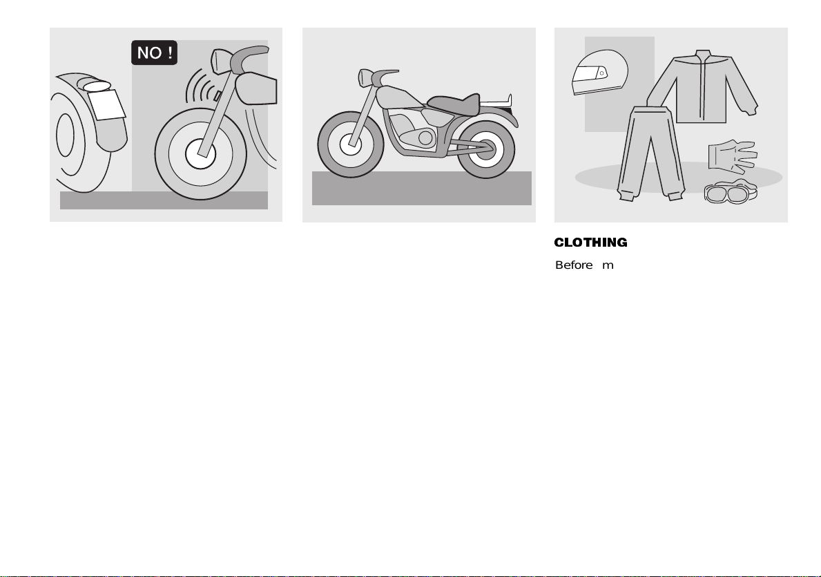
&/27+,1*
Before moving off, always wear your
crash helmet, correctly fastened. Make
sure that i t is homolog ated, soun d, of the
right size and t hat the visor is cl ean.
Wear protective clothing, preferably in
light and/or reflecting colours.
This way you will make yourself more
visible to other drivers, thus notably re-
ducing the risk of being knocked down,
and you will be more protected in case of
fall. Th is clothing should be ver y close-fit-
ting and fast ened at the extremit i es.
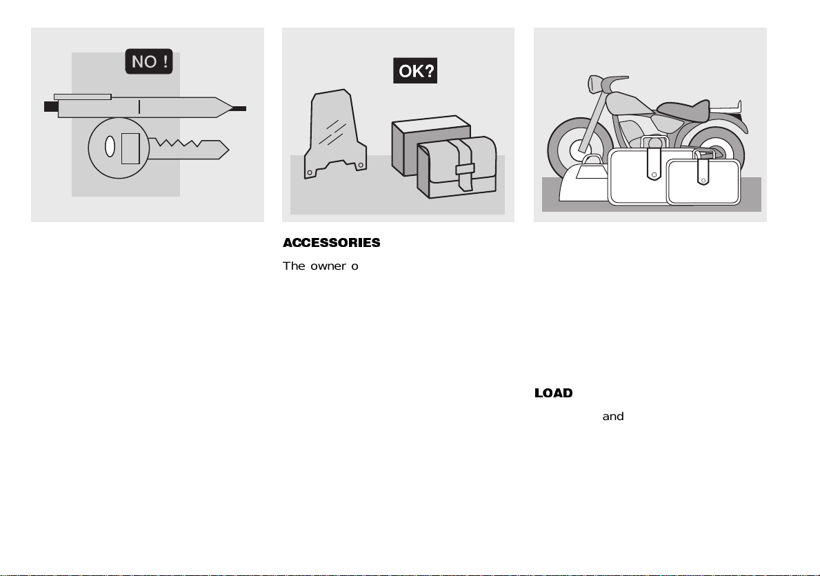
Strings, belts and ties should not be
hanging dow n; pr event these or ot her ob-
jects f rom interfering in the drive by get-
ting entangled with moving parts or
driving mec hanisms. Do not keep obj ects
which can be dangerous in case of fall,
for example pointed objects like keys,
pens, glass vials etc. in your pockets
(the same reco mmendati ons are valid for
any passeng er , too ) .
A12
345
ONLY ORIGINALS
9
Do not keep objects which can be dan-
gerous in case of fall, for example
pointed objects like keys, pens, glass
vials etc. in your po ckets ( the same rec-
ommendations are valid for any pas-
senger, too) .
$&&(6625,(6
The owner of the vehicle is responsible
for the choice, installation and use of any
accessory.
Avoid installing accessories that cover
horns or lights or that could impair their
function, limit the suspension stroke and
the ste ering an gle , hamper the oper atio n
of the controls and reduce the distance
from th e groun d and the an gle of inc lina -
tion in turns.
Avoid usi ng accessori es that hamper ac -
cess to the controls, since this can pro-
long reaction times duri ng an em er gency.
Large fairings and windscreens assem-
bled on t he vehic le can produce ae rody-
namic forces capable of compromising
the stability of the vehicle itself while
driving.
Make sure that the equipment is well
fastened to the vehicle and is not dan-
gerous during the drive.
Do not install electrical devices and do
not modify those already existing to
avoid electrical overloads, because the
vehicle could suddenly stop or there
could be a dangerous current shortage
in the horn and in the lights.
/2$'
Be careful and moderate when loading
your l ugg ag e. It i s nece ss ary to k eep t he
luggag e as close a s possible t o the ba-
rycenter of the vehicle and to distribute
the load uniformly on the two sides, in
order to reduce any lack of balance to
the minimum.
Further, make sure that the load is firmly
secured to the vehicle, especially during
long trips.
10
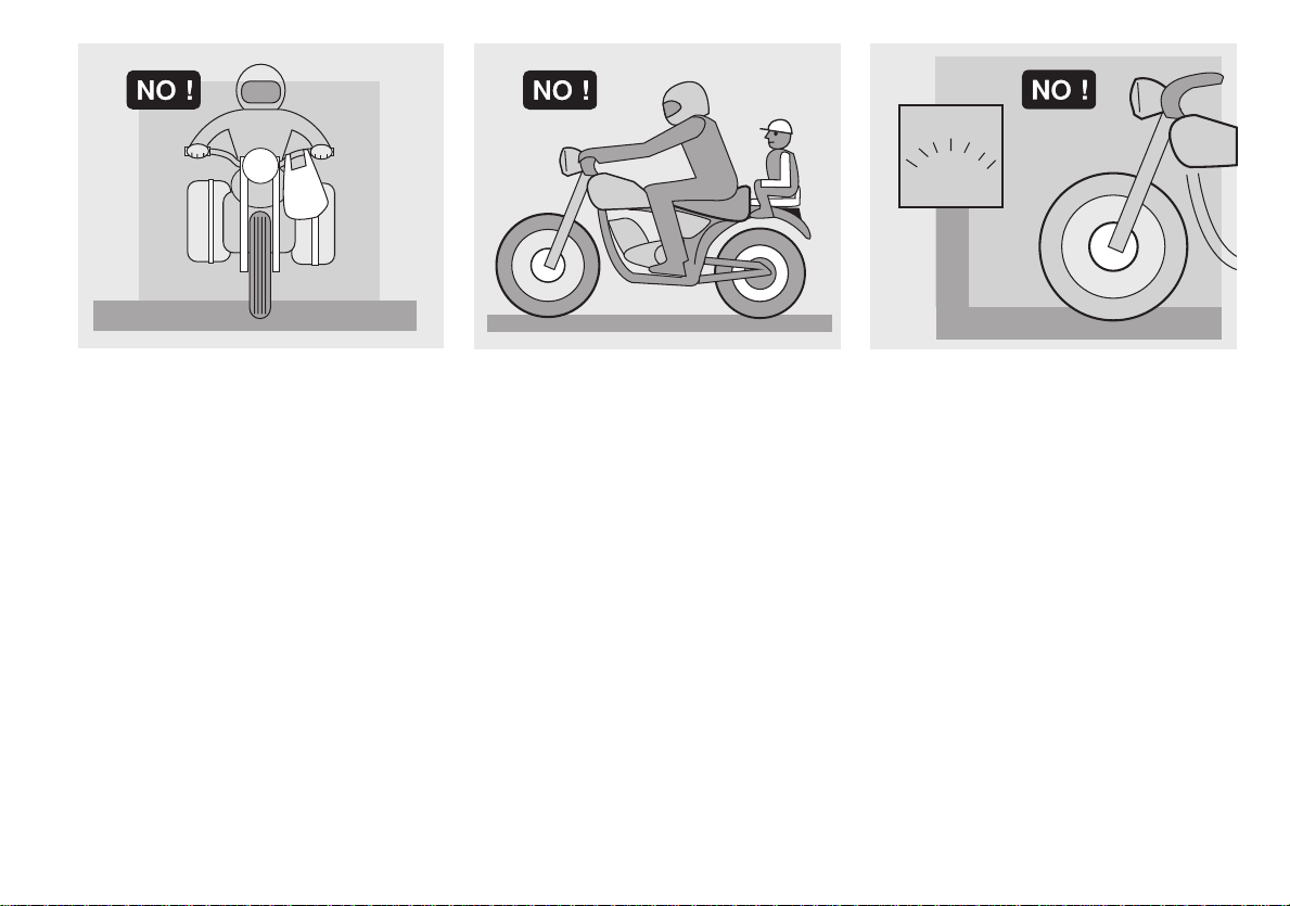
Absolutely do not hang bulky, volu-
minous, heavy and/or dangerous objects
on the handlebar, the mudguards and
the forks, as the vehicle could react
more slowly in turns and its manoeuvra-
bility could be unavoidably impaired.
Do not place too bulky bags on the ve-
hicle sides and do not hang the crash
helmet from the apposite string, a s they
could h it pe ople or obs tac les, thus c aus-
ing the loss of control of the vehicle.
Do not carry any bag if it is not tightly se-
cured t o the vehicle.
Do not carry bags which protrude too
much from the luggage-rack or which
cover the lights, the horn or the indica-
tors.
Do not carry animals or children on the
glove-compartment or on the luggage-
rack.
Do not exceed the maximum load allowed
for each side-bag.
When the vehicle is overloaded, its sta-
bility and its manoeuvrability can be com-
prom is ed.
KG!
11
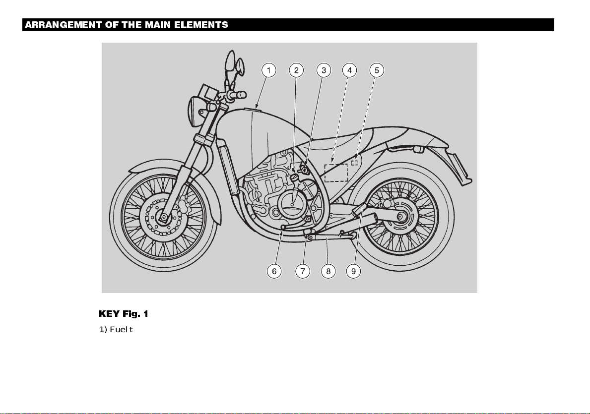
.(< )LJ
1) Fuel tank plug
2) Coolant expansi on tank plug
3) Crash helmet hook
4) Battery
5) Fuses
6) Transmission control lever
7) Footrest
8) Side stand
9) Passenger’ s foot res t
$55$1*(0(17 2) 7+( 0$,1 (/(0(176
Fig. 1
12
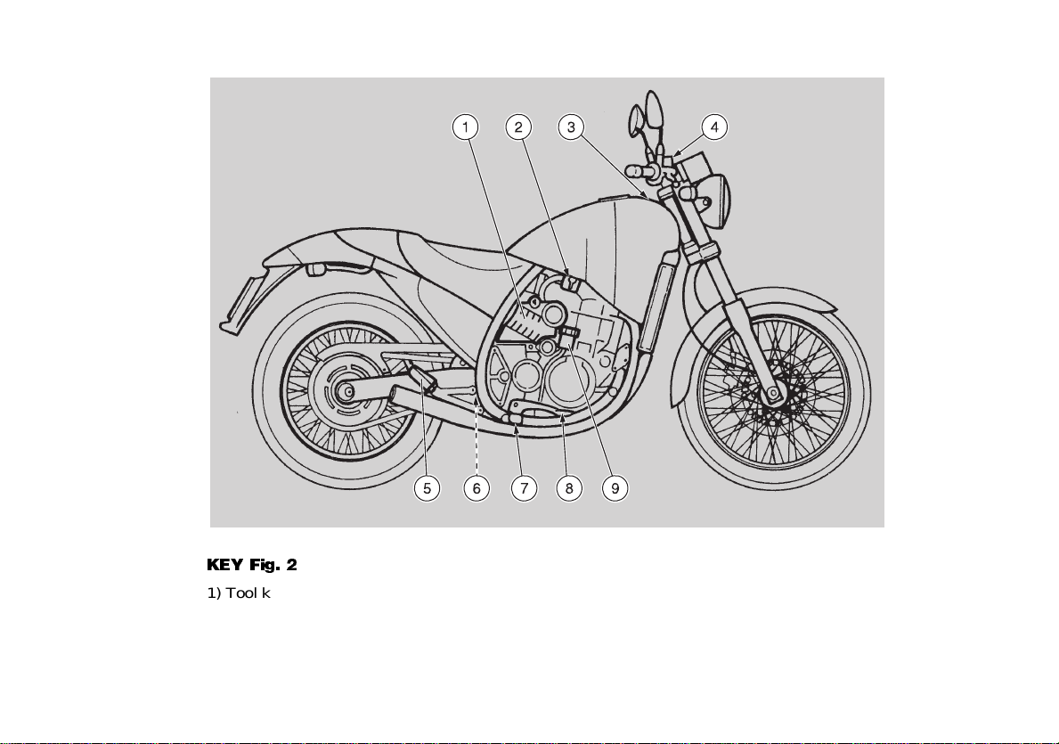
.(< )LJ
1) Tool kit/glove compartment
2) Fuel tap
3) Motor oil inlet hole plug/stick
4) Front brake fl uid ta nk
5) Passenger’s foot r est
6) Rear suspension spring-loading adjusting
nut
7) Footrest
8) Rear brake cont ro l lever
9) Rear brake fluid t ank
Fig. 2
13
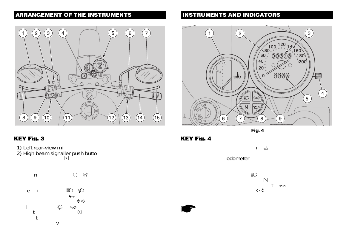
Fig. 3
$55$1*(0(17 2) 7+( ,167580(176
Fig. 4
,167580(176 $1' ,1',&$7256
.(< )LJ
1) Left rear-view m irro r
2) High beam sig nall er pu sh but ton
3) Cold start lever (
)
4) Ignition swi t ch
5) Instrument s and indicators
6) Engine st op swi t ch (
-
)
7) Right rear-view mirro r
8) Clutch co ntrol l ever
9) Headlight switch (
-
)
10) Horn pus h but t on (
)
11) Tu rn indicator switch (
(
)
12) Light switchi (
-
- •)
13) Starting push button (
)
14) Thrott l e grip
15) Front br ake lever
.(< )LJ
1) Coolant temper at ure ind icat or (
)
2) Speedometer
3) Total kilometres odometer
4) Trip odometer co nt rol kno b
5) Trip odometer
6) High beam warni ng lig ht (
)
7) Neutral indica tor war ni ng lig ht (
)
8) Low motor oil pressur e w ar ning l ight (
)
9) Turn indicator wa rning ligh (
(
)
Remember:
1 mi = 1,6 km
1 km = 0,625 mi
14

DESCRIPTION FUNCTION
Revolution counter It indicates the number of engine rev olutions per minute.
Speedometer It indicates the driving speed.
Total kilometres odometer It indicates the total number of kilometres covered.
Trip odometer It indicates the partial number of kilometres covered.
Trip odometer co ntrol knob By rotating it c lockwise, it is possible to set the trip odometer to zero.
High beam warning light
It comes on when the headlight is in "high beam" position.
Idle indicator warning light
It comes on when the transmission is in neutral.
Turn indicator warning light
(
It blinks when one of the turn indicators is on.
Low motor oil pressure warning light
It comes on every time the key is turned to the "
ON
" position and the engine isn’t running, checking
the proper functioning of the lamp.
If during this phase the lamp doesn’t turn on, it must be replaced.
The war ning light must go out w hen the engine starts running, exception made for the cases in which
the engine is hot and is nearly idling.
If the warning light turns on during the norma l runnin g of the engine, this me ans that the
oil pressure in the circuit is below the usual operating value. In this case, prov ide for
immediate topping up.
Coolant temperature indicator
It indicates the coolant temperature.
,167580(176 $1' ,1',&$7256
15
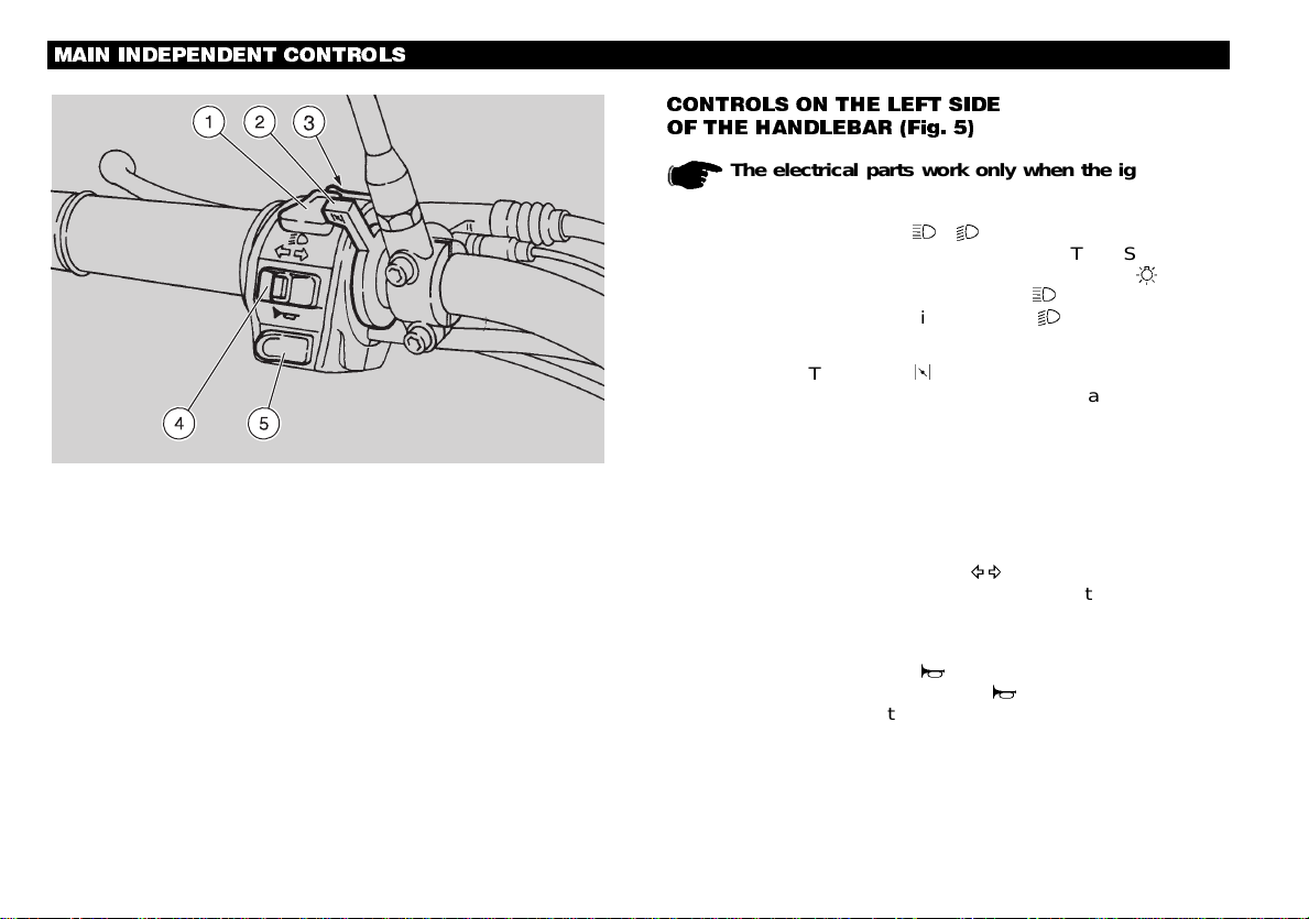
&21752/6 21 7+( /()7 6,'(
2) 7+( +$1'/(%$5 )LJ
The electrical parts work only when the ignition key
is on the "ON" posi tion.
1) HEADLIGHT SWITCH (
-
)
When the light switch, see p. 17 (CONTROLS ON THE
RIGHT SIDE OF THE HANDLEBAR) is on the "
", posi-
tion, if the headlight switch is on the "
" position, the high
beam comes on, while if it is on the "
" position, the low
beam comes on.
2) COLD START LEVER (
)
The starter for the engine cold start is operated by rotating
the cold start lever downwards. To disconnect the starter, it is
necessary to rot at e th e le ver com plet el y upw ar ds.
3) HIGH BEAM SIGNALLER PUSH BUTTON
This push button makes it possible to use the high beam sig-
naller, which is useful to send signals to the forthcoming ve-
hicles when pas sing and in case of danger or emerg ency .
4) TURN INDICATOR SWITCH (
(
)
To indicate the turn to the left, move the switch to the left; to
indicate the turn to the right, move the switch to the right.
To turn off the turn indicator, press the switch.
5) HORN PUSH BUTTON (
)
The horn is operated when the "
" push button is pressed
with the ignition key on the "ON" position.
Fig. 5
0$,1 ,1'(3(1'(17 &21752/6
16
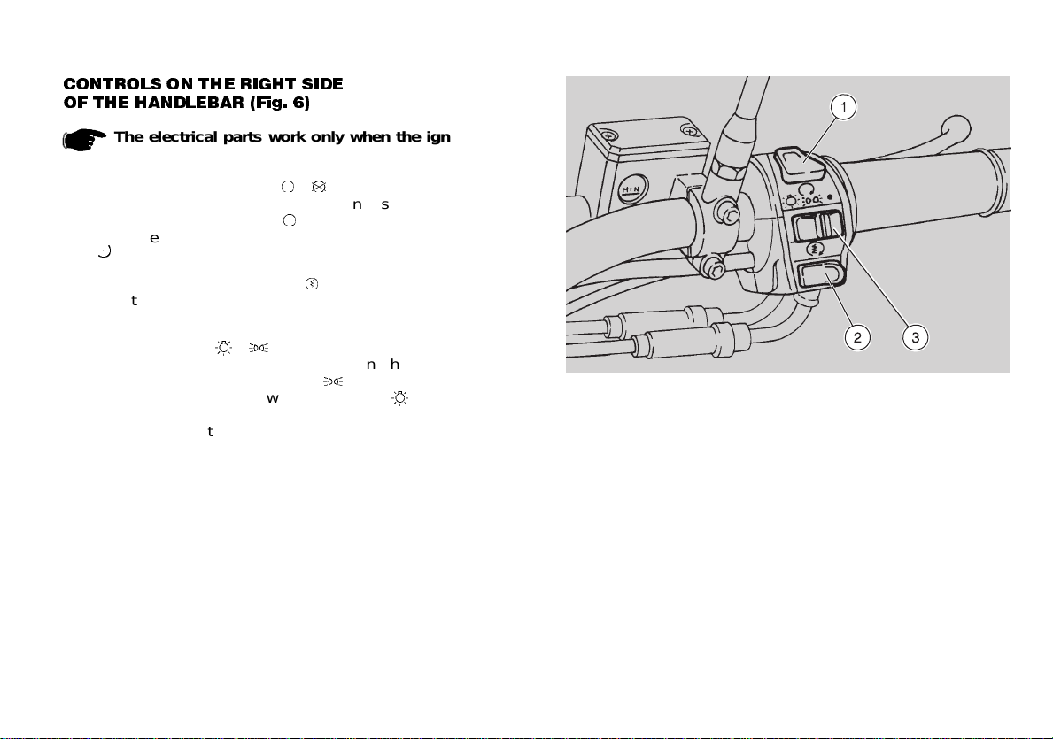
&21752/6 21 7+( 5,*+7 6,'(
2) 7+( +$1'/(%$5 )LJ
The electrical parts work only when the ignition key
is on the "ON" position.
1) ENGINE STOP SWITCH (
-
)
It mainly serves as a saf et y or emer gency switch.
When the switch is on the "
" position, it is possible to start
the engine; the engine is stopped by moving the switch to the
"
" position.
2) STARTING PUSH BUTTON (
)
When the starting push button is pressed, the starter makes
the engine run. For th e starti ng, see p. 28 (STARTING).
3) LIGHT SWITCH (
-
- •)
When the switch is on the " • " position, the headlights are
off; when the switch is on the "
" posit ion, the pa rking
lights are on; when the switch is on the "
" pos ition , the
low beams are on.
It is possible to turn on the high beams by means of the
headlight switch, see p. 16 (CONTROLS ON THE LEFT
SIDE OF THE HANDLEBAR).
Fig. 6
17
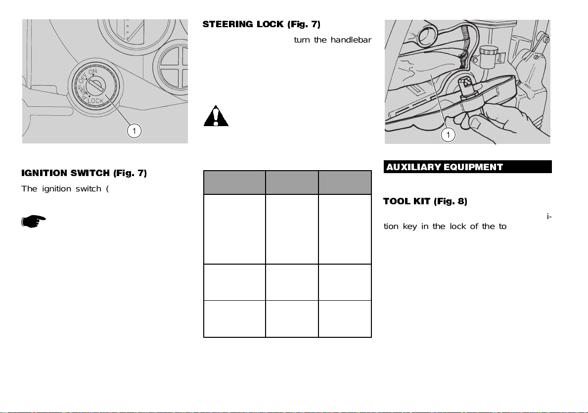
Fig. 7
,*1,7,21 6:,7&+ )LJ
The ignition switch (1) is positioned on
the steering tube plate.
The key operates the ignition
switch/steering lock and opens
the tool kit/glove compartment,
the fuel tank plug and the crash helmet
hook.
Two keys are supp lied together with the
vehicle (one spar e key).
67((5,1* /2&. )LJ
To lock the steering, turn the handlebar
leftwards co mpletely with the ke y on the
"
OFF
" positi on, press the key, r elease it
and turn it to the "
LOCK
" position.
Extract the key.
Never turn the key to the "LOCK"
position while driving, in order to
avoid losing control of the ve-
hicle.
POSITION FUNCTION
KEY
REMOVAL
LOCK
Steering lock
The steering is
locked.
It is neither
possible to
start the
engine, nor to
switch on the
lights.
It is possible to
remove the
key.
OFF
Neither the
engine, nor the
lights can be
switched on.
It is possible to
remove the
key.
ON
The engine
and the lights
can be
switched on.
It isn’t possible
to remove the
key.
$8;,/,$5< (48,30(17
722/ .,7 )LJ
To reach the tool kit, introduce the igni-
tion key in the lock of the tool kit/glove
compartment and turn it anticlockwise.
The tool kit (1 ) includes:
no. 1 tool case
no. 1 4 mm hexagon spanner
no. 1 5 mm hexagon spanner
no. 1 6 mm hexagon spanner
no. 1 8 mm hexagon spanner
no. 1 5.5/6.2 mm dou ble-ended spanner
no. 1 8/11 mm double- ended spanner
no. 1 10/13 mm double- ended spanner
no. 1 17 mm non-adjustable spanner
no. 1 22 mm hexagon sp anne r with handle
no. 1 extension for spanner with handle
no. 1 25 mm spark plug spanner
no. 1 screwdriver f or cr oss-slotted scr ews
Fig. 8
18
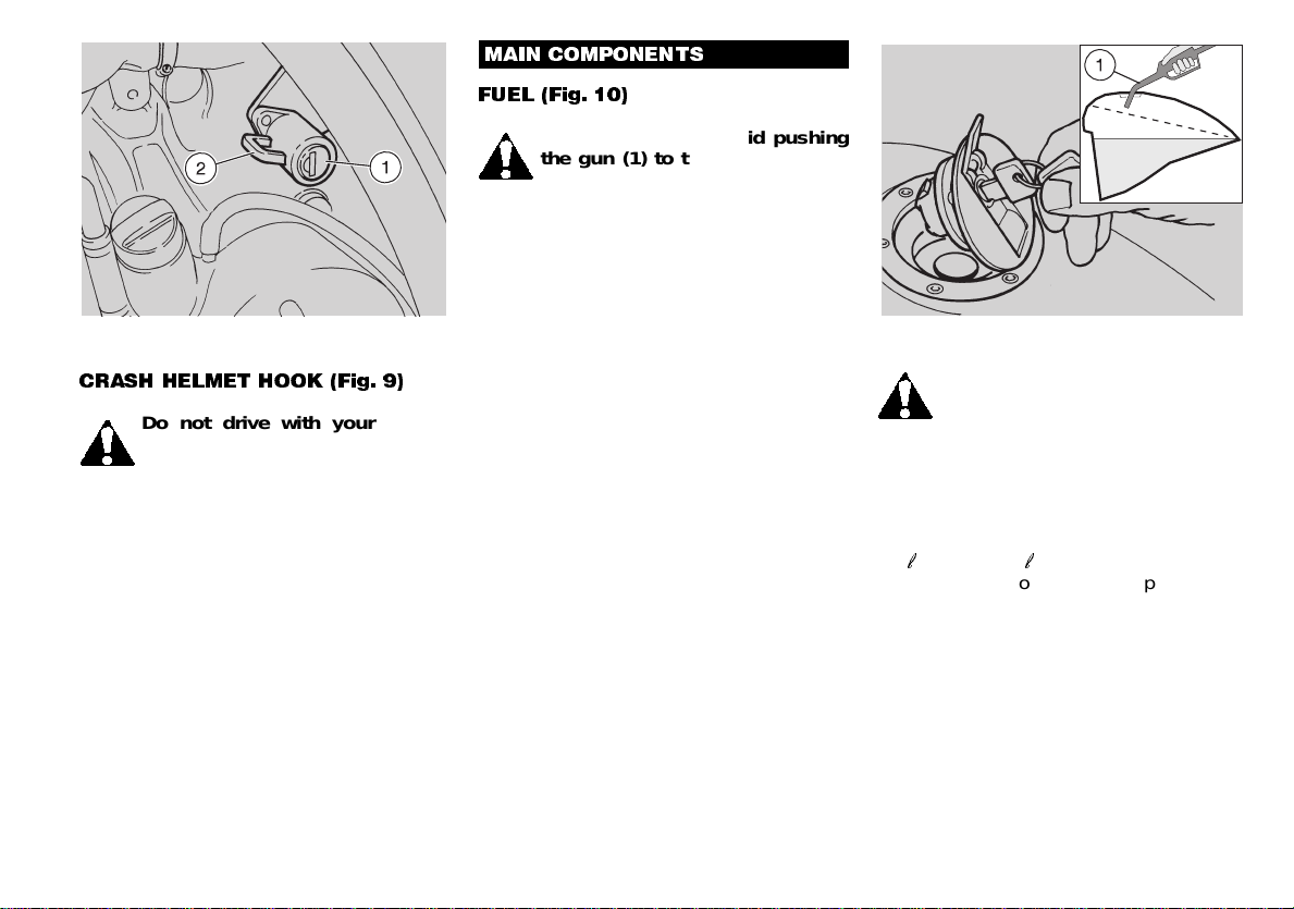
&5$6+ +(/0(7 +22. )LJ
Do not drive with your helmet
hanging from the hook, as this
could compromise your safety
while driving.
Thanks to this hook , you no longer have
to carry the crash helmet with yourself
every time you park the vehicle.
To hang the cras h helmet, introduce the
key in the lock (1), rotate it anticlockwise
and pass the s pecial lo oped w ire t hroug h
the hook (2).
Close the hook and rotate th e key clock-
wise.
Make sure that the hook has been
properly cl osed.
Fig. 9
0$,1 &20321(176
)8(/ )LJ
Duri ng ref uellin g, avoi d pushi ng
the gun (1) to the buttom of the
tank, in order to prevent fuel
from flowing out of the filler.
Screw the plug up carefully after re-
fuelling.
The fuel used for internal combustion
engines is extremely inflammable and
in particular conditions it can become
explosive.
It is important to carry out the refuelling
and the maintenance operations in a
well-ventilated area, with the engine off.
Do not smoke while refuelling or near
fuel vapo ur s, in any case avoid any con-
tact with free flames, sparks and any
other heat source to prevent the fuel
from catching fire or from exploding.
Further, prevent fuel from flowing out
of the fuel filler, as it could catch fire
when getting in contact with the red-hot
surfaces of the engine.
In case some fuel has accidentally been
spilt, make sure that the area has com-
pletely dried and before starting the ve-
hicle verify that there is no fuel inside
the fuel filler neck.
Avoid any contact of the fuel with the
skin and the inhalation of vapours; do
not swallow fuel or pour it from a re cep-
tacle into another by means of a tube.
KEEP AWAY FROM CHILDREN
Fig. 10
Since unleaded petrol expands
under the heat of the sun and
due to the effects of sun radia-
tion , n ever fi ll the tank to the b rim.
Use only unleaded petrol, in conformity
with the DIN 51607 standa rd, min. O.N.
95 (N.O.R.M.) and 85 (N.O.M.M.).
The fuel tank capacity is approximately
16
E
, about 2,5
E
of which make up the
reserve. To unlock the tank plug, insert
the ignition key in the lock and turn it
clockwise (Fig. 10).
19
(1*,1( 2,/
It is necessary to change the engine oil
after the first 1000 km and afterwards
every 6000 km, see p. 37 (CHANGING
THE ENGINE OIL AND THE OIL FIL-
TER); to check the oil level, see p. 36
(CHECKING THE ENGINE OIL LEVEL
AND TOPPING UP).
Remember:
1 mi = 1,6 km
1 km = 0,625 mi
Oil can c ause se vere damag es
to the skin if handled every
day and for long. Wash your
hands carefully after using it.
If the vehicle is used in very
dusty areas, the oil should be
change d m ore freque nt ly.
Do not dispose of oil in the environ-
ment. Put it in a sealed container and
take it to the filling station where you
usually buy it.
aprilia recommends:
see p. 59 (LUB RICANT CHART).
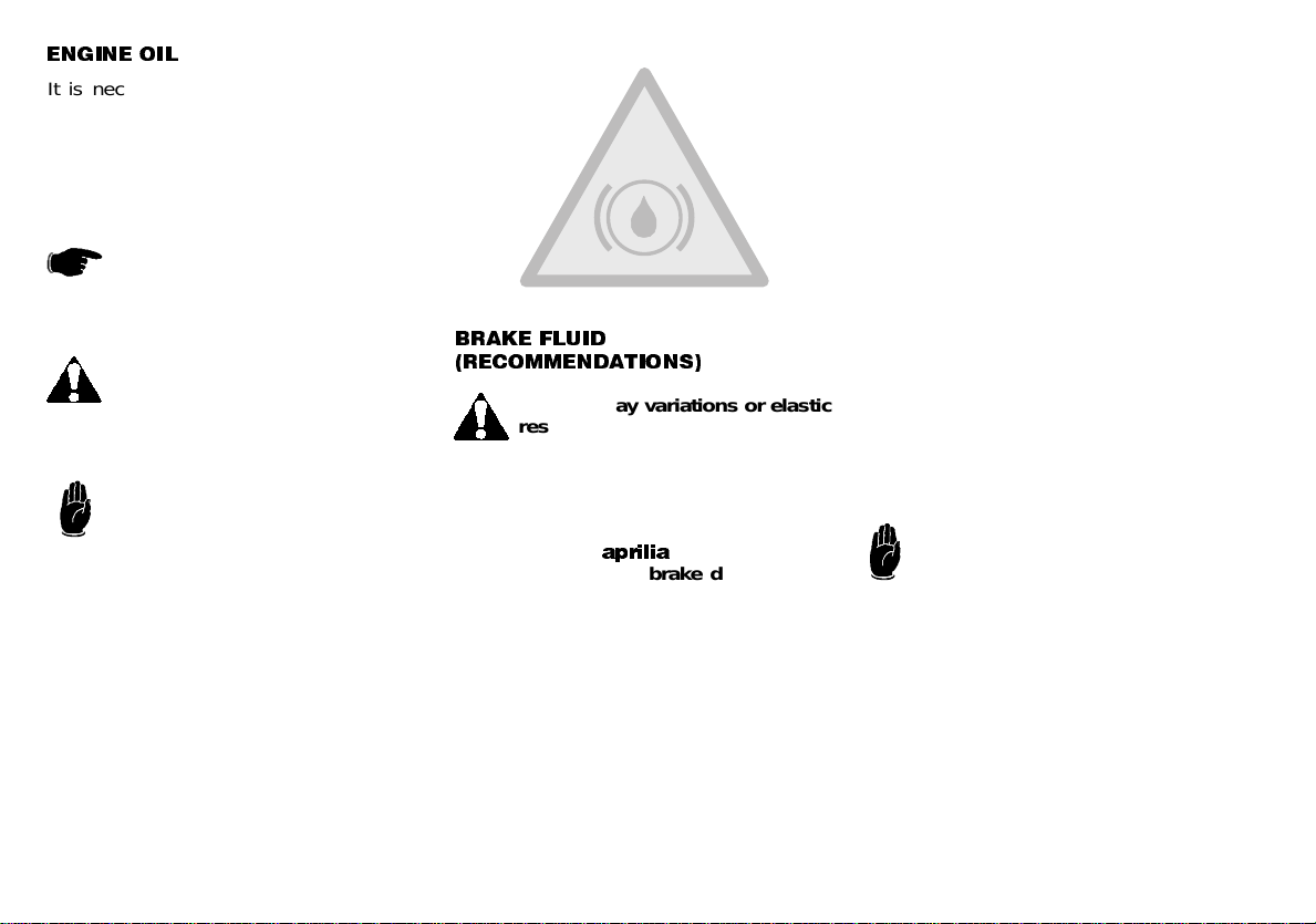
%5$.( )/8,'
5(&200(1'$7,216
Sudden play variations or elastic
resistance on the brake lever are
due to troubles in the hydraulic
system. For any doubt regarding the
perfect functioning of the braking sys-
tem and in case you are not able to
carry out the usual checking operation-
s, contact your
DSULOLD
Official Dealer.
Make sure that the brake disc and the
friction surface are neither oily nor
greasy, especially after maintenance or
checking operations.
Check that the brake cables are neither
twisted nor worn out.
Prevent water or dust from accidentally
getting into the circuit.
If the brake fluid gets in contact with
the skin or the eyes, it can cause
serious irritatio ns.
Carefully wash the parts of your body
that get in contact with the liquid.
Consult a doctor or an oculist if the liq-
uid gets in contact with your eyes .
Do not dispose of brake fluid in the en-
vironment.
KEEP AWAY FROM CHILDREN
When using the brake fluid, take
care not to spill it on the plastic
or painted parts, since it can
damage them.
20
 Loading...