


 Loading...
PEGASO 650 I.E.
use+maintenancebook 
aprilia part# 8104312

© 2001 aprilia s.p.a. - Noale (VE)
First edition: January 2001
Reprint: January 2002, November 2002,
May 2003, February 2004
Produced and printed by:
DECA s.r.l.
Via Risorgimento, 23/1 - Lugo (RA) - Italia
Tel. +39 - 0545 35235
Fax +39 - 0545 32844
E-mail: deca@decaweb.it
www.decaweb.it
on behalf of: aprilia s.p.a.
via G. Galilei, 1 - 30033 Noale (VE) - Italia Tel. +39 - 041 58 29 111
Fax +39 - 041 44 10 54 www.aprilia.com
SAFETY WARNINGS
The following precautionary warnings are used throughout this manual in order to convey the following messages:
Safety warning. When you find this symbol on the vehicle or in the
manual, be careful to the potential risk of personal injury. Non-compliance with the indications given in the messages preceded by this symbol may result in grave risks for your and other people’s safety and for the vehicle!
 WARNING
Indicates a potential hazard which may result in serious injury or even death.
 CAUTION
Indicates a potential hazard which may result in minor personal injury or damage to the vehicle.
NOTE The word “NOTE” in this manual precedes important information or instructions.
TECHNICAL INFORMATION
HThe operations preceded by this symbol must be repeated also on
the opposite side of the vehicle.
If not expressly indicated otherwise, for the reassembly of the units repeat the disassembly operations in reverse order.
The terms “right” and “left” are referred to the rider seated on the vehicle in the normal riding position.
WARNINGS - PRECAUTIONS - GENERAL ADVICE
Before starting the engine, carefully read this manual and in particular the section “SAFE DRIVE”.
Your and other people’s safety depends not only on your quickness of reflexes and on your agility, but also on what you know about the vehicle, on its efficiency and on your knowledge of the basic information for “SAFE DRIVE”. Therefore, get a thorough knowledge of the vehicle, in such a way as to be able to drive in the traffic safely.
NOTE Keep a stock of one bulb per type with the vehicle (see technical data).
2 use and maintenance Pegaso 650 I.E.
NOTE This manual must be considered as an integral part of the vehicle and must always accompany it, even in case of resale.
aprilia has carried out this manual with the maximum attention, in order to supply the user with correct and updated information. However, since aprilia constantly improves the design of its products, there may be slight discrepancies between the characteristics of your vehicle and those described in this manual. For any clarification concerning the information contained in this manual, do not hesitate to contact your aprilia Official Dealer.
For control and repair operations not expressly described in this publication, for the purchase of aprilia genuine spare parts, accessories and other products, as well as for specific advice, contact exclusively aprilia Official Dealers and Service Centers, which guarantee prompt and accurate assistance.
Thank you for choosing aprilia. We wish you a nice ride.
All rights as to electronic storage, reproduction and total or partial adaptation, with any means, are reserved for all Countries.
NOTE In some countries the antipollution and noise regulations in force require periodical inspections.
The user of the vehicle in these countries must:
–contact an aprilia Official Dealer to have the non-homologated components replaced with others homologated for use in the country in question;
–carry out the required periodical inspections.
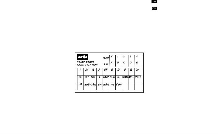
NOTE Soon after purchasing the vehicle, write down the identification data indicated on the SPARE PARTS IDENTIFICATION LABEL in the table here below. This label is positioned on the left side of the saddle support; to read it, it is necessary to remove the saddle, see p. 18 (UNLOCKING/LOCKING THE SADDLE).
These data indicate:
–YEAR = year of manufacture (Y, 1, 2, ...);
–I.M. = modification code (A, B, C, ...);
–COUNTRY CODES = homologation country (I, UK, A, ...).
and are to be supplied to the aprilia Official Dealer as reference data for the purchase of spare parts or specific accessories of the model you have acquired.
In this manual the various versions are indicated by the following symbols:
J optional
TIBET version
coolant expansion tank variant
L catalytic version |
|
|
VERSION: |
|
|
+ Italy |
2 |
Singapore |
4 United |
P Slovenia |
|
Kingdom |
|
|
> Austria |
F Israel |
|
M Portugal |
e South Korea |
|
( Finland |
- Malaysia |
|
$ Belgium |
@ Chile |
|
A Germany |
* Croatia |
|
C France |
# Australia |
|
' Spain |
R United States of |
|
|
|
America |
) Greece |
g Brazil |
|
/ Holland |
1 South Africa |
|
6 Switzerland |
K New Zealand |
|
& Denmark |
% Canada |
|
, Japan |
|
|
use and maintenance Pegaso 650 I.E. 3

TABLE OF CONTENTS |
|
SAFETY WARNINGS................................................. |
2 |
TECHNICAL INFORMATION..................................... |
2 |
WARNINGS - PRECAUTIONS - GENERAL ADVICE 2 |
|
SAFE DRIVE .............................................................. |
5 |
BASIC SAFETY RULES ....................................... |
6 |
CLOTHING ........................................................... |
8 |
ACCESSORIES .................................................... |
8 |
LOAD .................................................................... |
9 |
ARRANGEMENT OF THE MAIN ELEMENTS ........ |
10 |
ARRANGEMENT OF THE |
|
INSTRUMENTS/CONTROLS................................... |
12 |
INSTRUMENTS AND INDICATORS........................ |
13 |
INSTRUMENTS AND INDICATORS TABLE......... |
14 |
MAIN INDEPENDENT CONTROLS......................... |
16 |
CONTROLS ON THE LEFT PART OF THE |
|
HANDLEBAR ...................................................... |
16 |
CONTROLS ON THE RIGHT PART OF THE |
|
HANDLEBAR ...................................................... |
16 |
IGNITION SWITCH............................................. |
17 |
STEERING LOCK............................................... |
18 |
AUXILIARY EQUIPMENT ........................................ |
18 |
UNLOCKING/LOCKING THE SADDLE.............. |
18 |
GLOVE/TOOL KIT COMPARTMENT ................. |
19 |
ANTI-THEFT HOOK ........................................... |
19 |
REAR LUGGAGE RACK .................................... |
19 |
SPECIAL TOOLS J......................................... |
20 |
ACCESSORIES .................................................. |
20 |
SIDE BAGS J(supplied as standard equipment in |
|
the countries where required) ............................. |
21 |
REAR CASE J (supplied as standard |
|
equipment in the countries where required)........ |
23 |
MAIN COMPONENTS.............................................. |
24 |
FUEL................................................................... |
24 |
BRAKE FLUID - recommendations..................... |
26 |
DISC BRAKES.................................................... |
27 |
FRONT BRAKE .................................................. |
28 |
REAR BRAKE..................................................... |
30 |
COOLANT........................................................... |
31 |
TYRES ................................................................ |
33 |
ENGINE OIL ....................................................... |
34 |
CLUTCH ............................................................. |
35 |
ADJUSTING THE REAR BRAKE CONTROL |
|
LEVER CLEARANCE ........................................ |
36 |
CATALYTIC EXHAUST SILENCERS L.......... |
36 |
EXHAUST SILENCERS..................................... |
37 |
INSTRUCTIONS FOR USE ..................................... |
37 |
GETTING ON AND OFF THE VEHICLE ........... |
37 |
PRELIMINARY CHECKING OPERATIONS ...... |
39 |
PRELIMINARY CHECKING OPERATIONS ...... |
40 |
STARTING ......................................................... |
41 |
DEPARTURE AND DRIVE ................................ |
44 |
RUNNING-IN...................................................... |
47 |
STOPPING......................................................... |
48 |
PARKING ........................................................... |
48 |
POSITIONING THE VEHICLE ON THE STAND 49 |
|
SUGGESTIONS TO PREVENT THEFT ............ |
50 |
MAINTENANCE ...................................................... |
51 |
REGULAR SERVICE INTERVALS CHART....... |
52 |
IDENTIFICATION DATA .................................... |
54 |
JOINTS WITH CLICK CLAMPS AND WITH |
|
SCREW CLAMPS .............................................. |
54 |
CHECKING THE ENGINE OIL LEVEL AND |
|
TOPPING UP ..................................................... |
55 |
FRONT WHEEL ................................................. |
56 |
REAR WHEEL ................................................... |
58 |
POSITIONING THE VEHICLE ON THE REAR |
|
SUPPORT STAND J...................................... |
61 |
POSITIONING THE VEHICLE ON THE FRONT |
|
SUPPORT STAND J...................................... |
61 |
DRIVE CHAIN .................................................... |
62 |
REMOVAL OF THE FUEL TANK....................... |
64 |
REMOVING THE OIL SUMP GUARD ............... |
65 |
REMOVING THE RIGHT AND LEFT SIDES ..... |
65 |
REMOVING THE DRIVE CHAIN GUARDS....... |
66 |
INSTALLING THE SIDE BAG SUPPORTS J |
|
(supplied as standard equipment in the countries |
|
where required) .................................................. |
66 |
INSTALLING THE REAR CASE SUPPORTS J |
|
(supplied as standard equipment in the countries |
|
where required) .................................................. |
68 |
REAR SUSPENSION......................................... |
69 |
REAR SUSPENSION WITH HYDRAULIC |
|
PRELOAD ADJUSTMENT J.......................... |
70 |
CHECKING THE BRAKE PAD WEAR............... |
71 |
IDLING ADJUSTMENT ...................................... |
72 |
ADJUSTING THE ACCELERATOR CONTROL 73 |
|
ADJUSTING THE COLD START CONTROL .... |
73 |
SPARK PLUG .................................................... |
74 |
BATTERY........................................................... |
76 |
CHECKING THE ELECTROLYTE LEVEL ......... |
77 |
CHECKING AND CLEANING THE |
|
TERMINALS....................................................... |
77 |
REMOVING THE BATTERY .............................. |
78 |
RECHARGING THE BATTERY ......................... |
79 |
INSTALLING THE BATTERY............................. |
79 |
LONG INACTIVITY OF THE BATTERY............. |
80 |
CHECKING THE SWITCHES ............................ |
80 |
CHANGING THE FUSES................................... |
81 |
ADJUSTING THE VERTICAL HEADLIGHT |
|
BEAM ................................................................. |
82 |
DASHBOARD LIGHTING................................... |
82 |
BULBS................................................................ |
83 |
CHANGING THE HEADLIGHT BULBS ............. |
83 |
CHANGING THE FRONT DIRECTION |
|
INDICATOR BULBS........................................... |
85 |
CHANGING THE REAR DIRECTION |
|
INDICATOR BULBS........................................... |
85 |
CHANGING THE REAR LIGHT BULB............... |
86 |
CHANGING THE NUMBER PLATE BULB ........ |
86 |
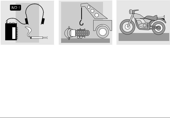
TRANSPORT........................................................... |
87 |
CLEANING .............................................................. |
87 |
LONG PERIODS OF INACTIVITY ..................... |
89 |
TECHNICAL DATA ................................................. |
90 |
LUBRICANT CHART.......................................... |
93 |
WIRING DIAGRAM - Pegaso 650 I.E. ............... |
94 |
WIRING DIAGRAM KEY - Pegaso 650 I.E. ....... |
95 |
Official Dealers and Service Centres ................. |
96 |
4 use and maintenance Pegaso 650 I.E.
SAFE DRIVE
safe drive
BASIC SAFETY RULES
To drive the vehicle it is necessary to be in possession of all the requirements prescribed by law (driving licence, minimum age, psychophysical ability, insurance, state taxes, vehicle registration, number plate, etc.).
Gradually get to know the vehicle by driving it first in areas with low traffic and/or private areas.
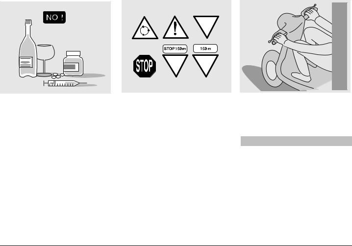
The use of medicins, alcohol and drugs or psychotropic substances notably increases the risk of accidents.
Be sure that you are in good psychophysical conditions and fit for driving and pay particular attention to physical weariness and drowsiness.
Most road accidents are caused by the driver’s lack of experience.
NEVER lend the vehicle to beginners and, in any case, make sure that the driver has all the requirements for driving.
Rigorously observe all road signs and national and local road regulations.
Avoid abrupt movements that can be dangerous for yourself and other people (for example: rearing up on the back wheel, speeding, etc.), and give due consideration to the road surface, visibility and other driving conditions.
Avoid obstacles that could damage the vehicle or make you lose control.
Avoid riding in the slipstream created by preceding vehicles in order to increase your speed.
 WARNING
Always drive with both hands on the handlebars and both feet on the footrests (or on the rider’s footboards), in the correct driving posture.
Avoid standing up or stretching your limbs while driving.
6 |
use and maintenance Pegaso 650 I.E. |
ONLY ORIGINALS
The driver should pay attention and avoid distractions caused by people, things and movements (never smoke, eat, drink, read, etc.) while driving.
Use only the vehicle’s specific fuels and lubricants indicated in the “LUBRICANT CHART”; check all oil, fuel and coolant levels regularly.
If the vehicle has been involved in an accident, make sure that no damage has occurred to the control levers, pipes, wires, braking system and vital parts.
If necessary, have the vehicle inspected by an aprilia Official Dealer who should carefully check the frame, handlebars, suspensions, safety parts and all the devices that you cannot check by yourself.
Always remember to report a ny malfunction to the technicians to help them in their work.
Never use the vehicle when the amount of damage it has suffered endangers your safety.
Never change the position, inclination or colour of: number plate, direction indicators, lights and horns.
Any modification of the vehicle will result in the invalidity of the guarantee.
Any modification of the vehicle and/or the removal of original components can compromise vehicle performance levels and safety or even make it illegal.
We recommend respecting all regulations and national and local provisions regarding the equipment of the vehicle.
In particular, avoid all modifications that increase the vehicle’s performance levels or alter its original characteristics.
Never race with other vehicles.
use and maintenance Pegaso 650 I.E. 7
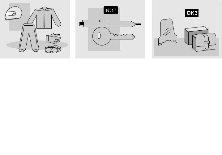
CLOTHING |
Before starting, always wear a correctly fastened crash helmet. Make sure that it is homologated, in good shape, of the right size and that the visor is clean.
Wear protective clothing, preferably in light and/or reflecting colours. In this way you will make yourself more visible to the other drivers, thus notably reducing the risk of being knocked down, and you will be more protected in case of fall.
This clothing should be very tight-fitting and fastened at the wrists and ankles; strings, belts and ties should not be hanging loose; prevent these and other objects from interfering with driving by getting entangled with moving parts or driving mechanisms.
Do not keep objects that can be dangerous in case of fall, for example pointed objects like keys, pens, glass vials etc. in your pockets (the same recommendations also apply to passengers).
ACCESSORIES
The owner of the vehicle is responsible for the choice, installation and use of any accessory.
Avoid installing accessories that cover horns or lights or that could impair their functions, limit the suspension stroke and the steering angle, hamper the operation of the controls and reduce the distance from the ground and the angle of inclination in turns.
Avoid using accessories that hamper access to the controls, since this can prolong reaction times d uring an emergency.
Big fairings and windshields installed on the vehicle may produce aerodynamic forces that affect the stability of the vehicle, especially when riding at high speed.
8 |
use and maintenance Pegaso 650 I.E. |
Make sure that the equipment is well fastened to the vehicle and not dangerous during driving.
Do not install electrical devices and do not modify those already existing to avoid electrical overloads, because the vehicle could suddenly stop or there could be a dangerous current shortage in the horn and in the lights.
aprilia recommends the use of genuine accessories ( aprilia genuine accessories).
LOAD
Be careful and moderate when loading your luggage. Keep any luggage loaded as close as possible to the center of gravity of the vehicle and distribute the load uniformly on both sides, in order to reduce umbalance to the minimum. Furthermore, make sure that the load is firmly secured to the vehicle, especially during long trips.
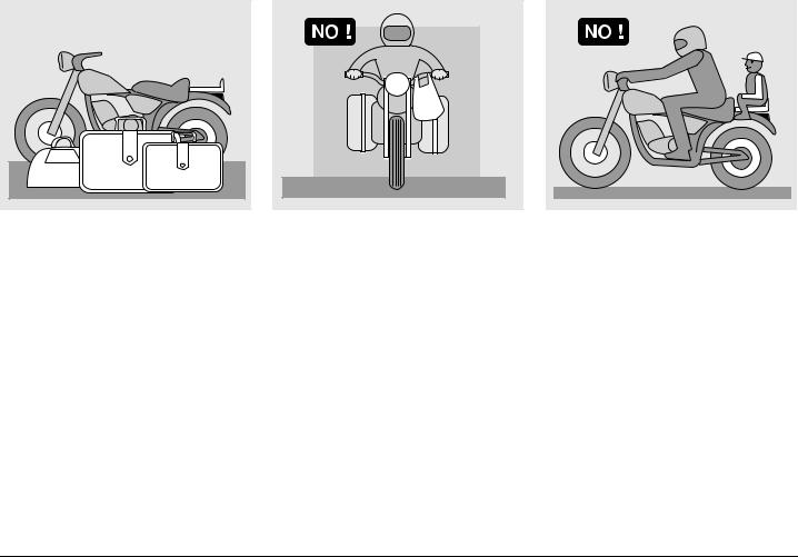
Avoid hanging bulky, heavy and/or dangerous objects on the handlebars, mudguards and forks, because the vehicle might respond more slowly in turns and its manoeuvrability could be unavoidably impaired.
Do not place bags that are too bulky on the vehicle sides and do not ride with the crash helmet, because they could hit people or obstacles, making you lose control of the vehicle.
Do not carry any bag if it is not tightly secured to the vehicle.
Do not carry bags which protrude too much from the luggage-rack or which cover the lights, horn or indicators.
Do not carry animals or children on the glove compartment or on the luggage rack.
Do not exceed the maximum load allowed for each side-bag.
When the vehicle is overloaded, its stability and its manoeuvrability can be compromised.
use and maintenance Pegaso 650 I.E. 9

ARRANGEMENT OF THE MAIN ELEMENTS
KEY |
|
|
|
|
|
|
|
1) |
Headlight |
9) |
Fuse carrier |
15) |
Centre stand J (*) |
|
|
2) |
Ignition switch/steering lock |
10) |
Passenger grab rail |
16) |
Side stand |
|
|
3) |
Left rear-view mirror |
11) |
Glove/tool kit compartment |
17) |
Rider left footrest |
|
|
4) |
Fuel tank filler cap |
12) |
Rear luggage rack |
18) |
Shifting lever |
|
|
5) |
Fuel tank |
13) |
Rear fork |
19) |
Not present |
. |
|
6) |
Coolant expansion tank cap |
14) |
Passenger left footrest |
|
Coolant expansion tank |
||
7) |
Battery |
|
(snapping, closed/open) |
19A) |
. Coolant expan- |
||
8) |
Electronic unit |
|
|
||||
|
|
|
|
sion tank |
|
||
|
|
|
|
|
|
|
|
20)Rear luggage rack J (*)
21)Left side bag J (*)
(*) = Supplied as standard equipment in the countries where required)
10 use and maintenance Pegaso 650 I.E.
|
|
|
|
|
|
|
|
|
|
|
|
|
|
|
|
|
|
|
|
|
|
|
|
|
|
|
|
|
|
|
|
|
|
|
|
|
|
|
|
|
|
|
|
|
|
|
|
|
|
|
|
|
|
|
|
|
|
|
|
|
|
|
|
|
|
|
|
|
|
|
|
|
|
|
|
|
|
|
|
|
|
|
|
|
|
|
|
|
|
|
|
|
|
|
|
|
|
|
|
|
|
|
|
|
|
|
|
|
|
|
|
|
|
|
|
|
|
|
|
|
|
|
|
|
|
|
|
|
|
|
|
|
|
|
|
|
|
|
|
|
|
|
|
|
|
|
|
|
|
|
|
|
|
|
|
|
|
|
|
|
|
|
|
|
|
|
|
|
|
|
|
|
|
|
|
KEY |
|
|
|
|
|
|
|
|
|
|
|
|
|
|
|
|
|
|
|
|
|
1) |
Rear light |
8) |
Engine oil level plug- |
15) |
Rear brake control lever |
20) |
Drive chain |
||||||||||||||
2) |
Passenger grab rail |
|
dipstick |
16) |
Rider right footrest |
21) |
Right side bag J(supplied |
||||||||||||||
3) |
Saddle lock |
9) |
Front brake fluid tank |
17) |
Anti-theft hook (for shielded |
|
as standard equipment in |
||||||||||||||
4) |
Saddle |
10) |
Right rear-view mirror |
|
cable |
“Body - Guard” |
|
the countries where |
|||||||||||||
5) |
Rear brake fluid tank |
11) |
Horn |
|
aprilia J) |
|
required) |
||||||||||||||
6) |
Air cleaner |
12) |
Engine oil tank |
18) |
Rear brake pump |
|
|
|
|
||||||||||||
7) |
Rear shock absorber |
13) |
Idle speed adjusting knob |
19) |
Passenger right footrest |
|
|
|
|
||||||||||||
|
|
14) |
Engine oil filter |
|
(snapping, closed/open) |
|
|
|
|
||||||||||||
use and maintenance Pegaso 650 I.E. 11
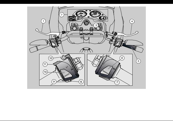
ARRANGEMENT OF THE INSTRUMENTS/CONTROLS
KEY
1)Clutch lever
2)Instruments and indicators
3)Ignition switch/steering lock ( - - )
4)Front brake lever
5)Throttle grip
6)Engine stop switch ( - )
7)Start push button ( )
8)Direction indicator switch ( )
9)Horn push button ( )
10)Dimmer switch ( - )
11)High beam signalling push button ( )
12)Cold start lever ( )
12 use and maintenance Pegaso 650 I.E.
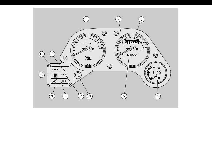
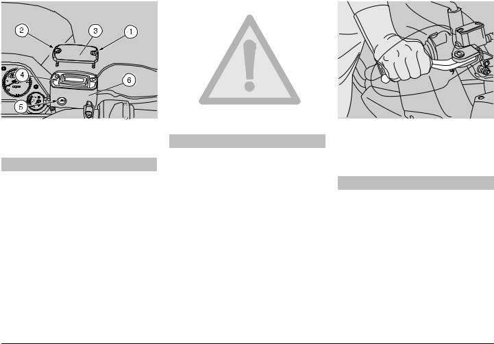
INSTRUMENTS AND INDICATORS
KEY
1)Revolution counter
2)Speedometer
3)Total kilometres odometer
4)Coolant temperature indicator ( )
5)Partial kilometres odometer
6)Trip meter resetting knob
7)Red engine oil pressure warning light ( )
8)Blue high beam warning light ( )
9)Red diagnostic warning light (c)
10)Amber low fuel warning light ( )
11)Green direction indicator warning light ( )
12)Green neutral indicator warning light ( )
use and maintenance Pegaso 650 I.E. 13

INSTRUMENTS AND INDICATORS TABLE
Description |
|
|
Function |
|
Direction indicator warning light |
|
|
Blinks when the direction indicators are on. |
|
|
|
|
|
|
High beam warning light |
|
|
Comes on when the high beam bulbs are on or when the headlight signaller is operated. |
|
|
|
|
|
|
Revolution counter rpm |
|
|
Indicates the number of revolutions of the engine per minute. |
|
|
|
|
Never exceed the engine max. speed rate, see p. 47 (RUNNING-IN). |
|
|
|
CAUTION |
||
|
|
|
|
|
|
|
|
|
|
Low fuel warning light |
|
|
It comes on when the quantity of fuel still available in the fuel tank is less than 5 b. |
|
|
|
|
In this case, top up as soon as possible, see p. 24 (FUEL). |
|
|
|
|
Comes on whenever the ignition switch is in position “ ” and the engine is not running, thus |
|
|
|
|
checking the functionality of the bulb. |
|
Engine oil pressure Warning light |
|
|
If the light does not come on in this phase, contact an aprilia Official Dealer. |
|
|
|
If the engine oil pressure warning light “ ” remains on after the |
||
|
CAUTION |
|||
|
|
|
start or comes on during the normal operation of the engine, this |
|
|
|
|
|
|
|
|
|
means that the engine oil pressure in the circuit is insufficient. |
|
|
|
|
In this case, stop the engine immediately and contact an aprilia Official Dealer. |
|
|
|
|
|
|
Neutral indicator warning light |
|
|
Comes on when the gear is in neutral. |
|
|
|
|
|
|
|
|
|
It comes on whenever the ignition switch is positioned on “ ” and goes out a few seconds after |
|
|
|
|
the engine start. |
|
|
|
|
|
Do not carry out any operation on the components of the vehicle |
|
|
|
CAUTION |
|
|
|
|
with the ignition switch in position “ ”. |
|
|
|
|
|
|
|
|
|
With the engine stop switch in position “ ”, it comes on whenever the ignition switch is |
|
Diagnostic warning light |
c |
|
positioned on “ ” and remains on, with low light intensity, thus checking the correct |
|
|
|
|
operation of the injection circuit. |
|
|
|
|
If the light does not come on in this phase, contact an aprilia Official Dealer. |
|
|
|
|
|
If the diagnostic warning light “c” remains on after the engine |
|
|
|
CAUTION |
|
|
|
|
start or comes on during the normal operation of the engine, this |
|
|
|
|
|
|
|
|
|
means that the electronic unit has detected an anomaly. In many cases the engine keeps |
|
|
|
|
running with limited functions; contact an aprilia Official Dealer immediately. |
|
|
|
|
|
|
|
|
|
|
Follow ¾ |
14 use and maintenance Pegaso 650 I.E.

Follow ¾
Description |
|
|
Function |
|
Speedometer (km/h) |
|
|
It indicates the driving speed. |
|
|
|
|
|
|
Total kilometres odometer |
|
|
It indicates the total number of kilometres covered. |
|
|
|
|
|
|
|
|
|
It indicates the approximate temperature of the coolant in the engine. |
|
|
|
|
When the pointer starts moving beyond the “40” level, the temperature is sufficient for driving |
|
|
|
|
the vehicle. |
|
|
|
|
The normal operating temperature appears on the graduated area of the scale. |
|
|
|
|
|
The switching on and off of the cooling fan does not depend on the |
|
|
|
CAUTION |
|
|
|
|
position of the ignition switch. To lower the coolant temperature, |
|
|
|
|
|
|
|
|
|
the cooling fan works even when the engine is off and it is disconnected automatically. |
|
|
|
|
|
If the maximum allowed temperature is exceeded (red area of the |
Coolant temperature indicator |
|
|
CAUTION |
|
|
scale), the engine may be seriously damaged. |
|||
|
|
|
|
|
|
|
|
If the pointer gets near the red area, stop the engine, wait until the cooling fan is disconnected |
|
|
|
|
and check the coolant level, see p. 31 (COOLANT). |
|
|
|
|
If the pointer reaches the red area, stop the vehicle and let the engine idle for approximately two |
|
|
|
|
minutes, thus permitting the regular circulation of the coolant in the system; then, position the |
|
|
|
|
engine stop switch on “ ” and check the coolant level, see p. 31 (COOLANT). If the situation on |
|
|
|
|
the dashboard remains the same after the coolant level has been checked, do not start the |
|
|
|
|
vehicle and contact an aprilia Official Dealer. |
|
Partial kilometres odometer |
|
|
It indicates the partial number of kilometres covered. To set it to zero, use the trip meter |
|
|
|
resetting knob. |
|
|
|
|
|
|
|
|
|
|
|
|
Trip meter resetting knob |
|
|
Rotate it anticlockwise to set the partial kilometres odometer to zero. |
|
|
|
|
|
|
use and maintenance Pegaso 650 I.E. 15
MAIN INDEPENDENT CONTROLS
CONTROLS ON THE LEFT PART OF THE HANDLEBAR
NOTE The electrical parts work only when the ignition switch is in position “ ”.
1)HORN PUSH BUTTON ( )
The horn is activated when the push button is pressed.
2)DIRECTION INDICATOR SWITCH ( )
To indicate the turn to the left, move the switch to the left; to indicate the turn to the right, move the switch to the right.
To turn off the direction indicator, press the switch.
3)DIMMER SWITCH ( - )
When it is in position “ ” the parking lights, the dashboard light and the low
beam are always on.
When it is in position “ ”, the high beam comes on.
4) HIGH BEAM SIGNALLING PUSH BUTTON ( )
It makes it possible to use the high beam for signalling to forthcoming vehicles while overtaking and in case of peril and/or emergency.
Press the push button to operate the high beam blinking
NOTE To disconnect the high beam blinking, release the push button.
5)COLD START LEVER ( )
The starter for the cold start of the
engine is operated by rotating the lever “ ” downwards.
To disconnect the starter, move the lever “ ” to its initial position.
CONTROLS ON THE RIGHT PART OF THE HANDLEBAR
NOTE The electrical parts work only when the ignition switch is in position “ ”.
6) ENGINE STOP SWITCH ( - )
 WARNING
Do not operate the engine stop switch “ - ” in running conditions.
This is a safety or emergency switch. With the switch pressed in position “ ”, it is possible to start the engine; when the switch is pressed to position “ ”, the engine stops.
 CAUTION
With stopped engine and ignition switch in position “ ”, the battery may discharge.
When the vehicle has come to rest, after stopping the engine, move the ignition switch to position “ ”.
7)START PUSH BUTTON ( )
When the start push button “ ” is pressed, the starter makes the engine run. For the starting, see p. 41 (STARTING).
16 use and maintenance Pegaso 650 I.E.
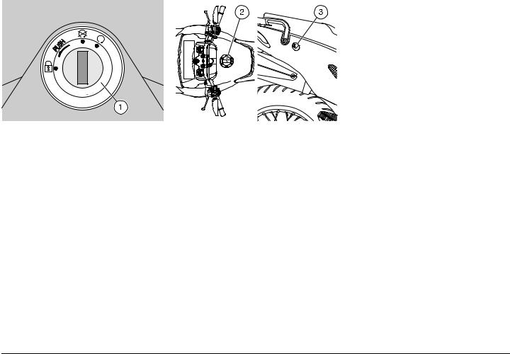
IGNITION SWITCH
The ignition switch (1) is positioned on the upper plate of the steering column.
NOTE The key operates the ignition switch/steering lock, the fuel tank lock (2) and the saddle lock (3).
Two keys are supplied together with the vehicle (one spare key).
NOTE Do not keep the spare key on the vehicle.
|
|
Position |
Function |
Key removal |
|
|
|
The steering |
It is possible |
|
|
is locked. It |
to remove the |
|
|
|
is not |
key. |
|
|
|
Steering |
possible to |
|
|
|
lock |
start the |
|
|
|
|
engine. |
|
|
|
|
|
|
|
|
|
The engine |
It is possible |
|
|
cannot be |
to remove the |
|
|
|
|
started. |
key. |
|
|
|
|
|
|
|
|
The engine |
It is not |
|
|
|||
|
|
can be |
possible to |
|
|
|
started. |
remove the |
|
|
|
|
|
key. |
|
|
|
|
|
use and maintenance Pegaso 650 I.E. 17
AUXILIARY EQUIPMENT
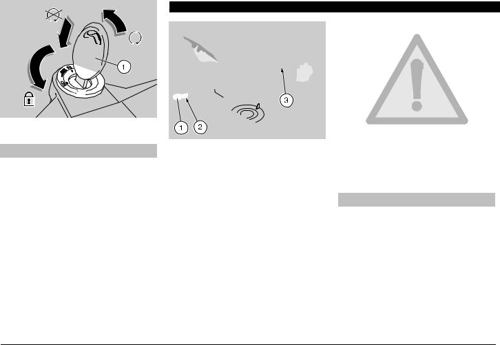
STEERING LOCK
 WARNING
Never turn the key to position “ ” in running conditions, in order to avoid losing control of the vehicle.
OPERATION
To lock the steering:
uTurn the handlebar completely leftwards.
uTurn the key (1) to position “ ”.
uPress the key (1) and rotate it to position “ ”.
uWithdraw the key (1).
UNLOCKING/LOCKING THE SADDLE
uPosition the vehicle on the stand, see p. 49 (POSITIONING THE VEHICLE ON THE STAND).
uInsert the key (1) in the saddle lock (2).
uTurn the key (1) clockwise and raise and remove the saddle.
NOTE Before lowering and locking the saddle, make sure that you have not left the key in the glove/tool kit compartment.
To lock the saddle:
uPosition the tangs (3) in the seat, lower and press the saddle, making the lock snap.
 WARNING
Before leaving, make sure that the saddle is properly locked.
18 use and maintenance Pegaso 650 I.E.
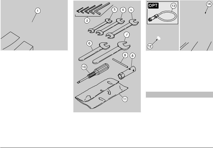
GLOVE/TOOL KIT COMPARTMENT
To reach the glove/tool kit compartment, proceed as follows:
u Remove the saddle, see p. 18 (UNLOCKING/LOCKING THE SADDLE).
The tool kit (1) includes:
– 3, 4, 5, 6, 8 mm bent hexagon spanners |
|
|
(2); |
|
|
– 5. 5 – 7 mm double fork spanner (3); |
|
|
– 8 – 11 mm double fork spanner (4); |
|
|
– 10 – 13 mm double fork spanner (5); |
|
|
– 19 mm simple fork spanner (6); |
|
|
– 24 mm simple fork spanner (7); |
|
|
– 18 mm socket spanner for spark plug |
Maximum allowed weight: 1.5 kg. |
|
(8); |
||
|
–socket spanner rod (9);
–double-ended, cross-/cut-headed screwdriver (10);
–tool case (11);
ANTI-THEFT HOOK
The anti-theft hook (12) is positioned on the right side of the vehicle, near the rider footboard.
To prevent the vehicle from being stolen, it is advisable to secure it with the shielded cable “Body-Guard” aprilia J (13), available at the aprilia Official Dealers .
 WARNING
Do not use the hook to lift the vehicle or for other purposes, since it has been designed exclusively to secure the vehicle once it has been parked.
REAR LUGGAGE RACK
Maximum weight allowed for the rear luggage rack (14): 9 kg
use and maintenance Pegaso 650 I.E. 19
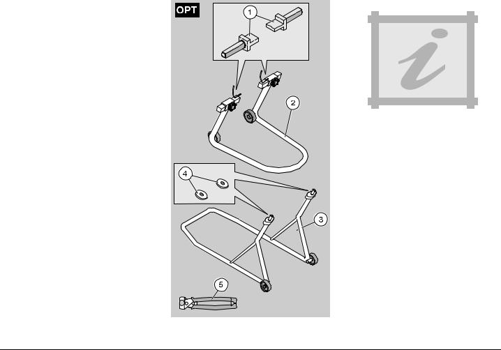
SPECIAL TOOLS J
To perform some specific operations, it is advisable to use the following special tools (to be requested to an aprilia Official Dealer):
Tool |
Operations |
|
|
|
Support pins (1) for the rear |
Positioning of |
|
|
|
support stand, see p. 61 |
the vehicle on |
|
|
|
(POSITIONING THE |
the rear stand. |
|
|
|
VEHICLE ON THE REAR |
|
|
|
|
SUPPORT STAND J). |
|
|
|
|
|
|
|
|
|
Rear support stand (2), see p. |
Rear wheel |
|
|
|
61 (POSITIONING THE |
disassembly. |
|
|
|
VEHICLE ON THE REAR |
Drive chain |
|
|
|
SUPPORT STAND J). |
adjustment. |
|
|
|
|
|
|
|
|
Front support stand (3), see p. |
Front wheel |
|
|
|
61 (POSITIONING THE |
disassembly. |
|
|
|
VEHICLE ON THE FRONT |
|
|
|
|
SUPPORT STAND J). |
|
|
|
|
Washer (4) for front support |
Front wheel |
|
|
|
stand, see p. 61 |
disassembly. |
|
|
|
(POSITIONING THE |
|
|
|
|
VEHICLE ON THE FRONT |
|
|
|
|
SUPPORT STAND J). |
|
|
|
|
Click clamp (5) installation |
Click clamp |
|
|
|
pliers, see p. 54 (CLICK |
|
|
|
|
installation. |
|
|
|
|
CLAMPS). |
|
|
|
|
|
|
|
|
|
|
|
|
|
|
|
|
|
|
|
|
|
|
|
|
|
|
|
|
|
|
|
|
|
|
ACCESSORIES
The vehicle may be equipped with the following accessories (to be requested to the aprilia Official Dealer):
–side bags J, see p. 21 [SIDE BAGS J (supplied as standard equipment in the countries where required)];
–rear case J, see p. 23 [REAR CASE J (supplied as standard equipment in the countries where required)];
–centre stand J (supplied as standard equipment in the countries where required).
20 use and maintenance Pegaso 650 I.E.
SIDE BAGS J (supplied as standard equipment in the countries where required)
Thanks to the use of the side bags it is possible to transport clothes or other objects even in bad weather, so that they are protected and do not constitute a hindrance or a risk for the rider.
NOTE If the side bags are not installed on the vehicle, before using them it is necessary to install the appropriate supports, see p. 66 [INSTALLING THE SIDE BAG SUPPORTS J (supplied as standard equipment in the countries where required)].
Clean and lubricate the coupling lock on the bag every 6000 km (3750 mi) or 12 months.
NOTE The following information refers to one unit only, but is valid for both.
To open the side bag, proceed as follows:
uPosition the vehicle on the stand, see p. 49 (POSITIONING THE VEHICLE ON THE STAND).
uIntroduce the key (1) in the lock.
uTurn the key (1) anticlockwise.
uExtract the key (1) and insert it in the other lock.
uTurn the key (1) anticlockwise.
uLift the two parts of the lock (2).
uOpen the case (3).
Two keys are supplied together with the vehicle (one spare key).
NOTE Do not keep the spare key on the vehicle.
 WARNING
If it is necessary to transport more than one object, distribute the load uniformly on the side bags.
Secure the luggage by means of the appropriate elastic belts, in such a way as to avoid dangerous movements of the same during the trip.
It is not advisable to use the vehicle with only one side bag installed.
Do not load the side bags excessively.
Maximum allowed weight: 5 kg (for each bag).
use and maintenance Pegaso 650 I.E. 21
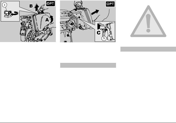
To remove the side bag, proceed as follows:
uIntroduce the key (4) in the lock.
uTurn the key (4) clockwise and at the same time move the lower part of the bag slightly towards the outside (A).
uGrasp the bag firmly with both hands, as indicated in the figure.
uLift the bag (B) slightly and release it (C) from the appropriate coupling seats (5) on the bag support.
Two keys are supplied together with the vehicle (one spare key).
NOTE Do not keep the spare key on the vehicle.
 CAUTION
Handle the plastic and painted components with care to avoid scraping or damaging them.
 WARNING
Upon reassembly, make sure that the bag is properly anchored to its support.
Upper part: perfect fitting of the bag coupling pins in the coupling seats provided on the support;
Lower part: perfect fitting of the support coupling pin in the relevant lock provided on the bag; when the lock snaps, the coupling is correct.
22 use and maintenance Pegaso 650 I.E.
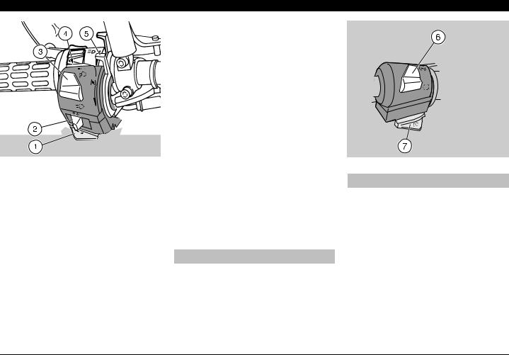
REAR CASE J (supplied as standard equipment in the countries where required)
Thanks to the use of the rear case, you no longer have to carry the crash helmet or other bulky objects with you every time you park the vehicle.
NOTE Write down your personal data on the appropriate plate positioned on the lock.
Clean and lubricate the coupling lock on the lower part of the case every 6000 km (3750 mi) or 12 months.
NOTE If the rear case is not installed on the vehicle, before using it, it is necessary to install the appropriate supports, see p. 68 (INSTALLING THE REAR CASE SUPPORTS J (supplied as standard equipment in the countries whe re required)).
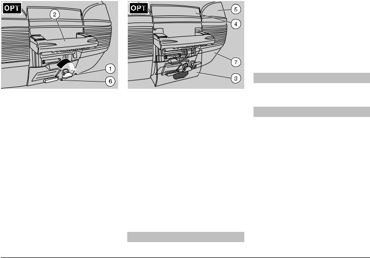
To open the rear case, proceed as follows:
uPosition the vehicle on the stand, see p. 49 (POSITIONING THE VEHICLE ON THE STAND).
uIntroduce the key (1) in the lock.
uRotate the key (1) clockwise.
uRemove the handle (2).
uLift the lock (3).
uRelease the upper part (4) of the lock (3) from the case (5).
uLift the upper part of the case to open it (5).
NOTE The case can contain two “FULLFACE” helmets.
Two keys are supplied together with the vehicle (one spare key).
NOTE Do not keep the spare key on the vehicle.
 WARNING
Do not load the rear case excessively.
Maximum allowed weight: 5 kg.
To remove the rear case, proceed as follows:
uIntroduce the key (1) in the lock.
uRotate the key (1) clockwise.
uExtract the handle (2) and grasp it firmly with one hand.
uPress the appropriate push button (6).
uLift the case (7) and withdraw it from the relevant front couplings.
 CAUTION
Handle the plastic and painted components with care to avoid scraping or damaging them.
 WARNING
Upon reassembly, make sure that the case is properly anchored to its support.
Front part: perfect fitting of the support coupling elements into the seats provided on the case;
Rear part: perfect fitting of the support coupling pin in the relevant lock on the case; when the lock snaps, the coupling is correct.
use and maintenance Pegaso 650 I.E. 23
MAIN COMPONENTS
FUEL
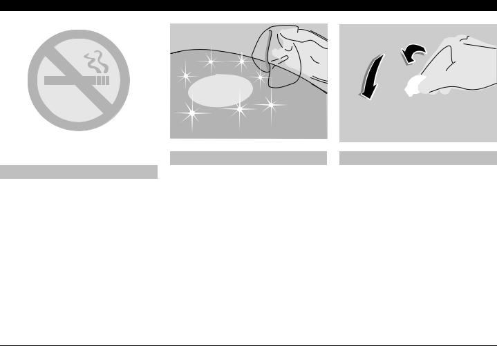
 WARNING
The fuel used for internal combustion engines is extremely inflammable and in particular conditions it can become explosive.
It is important to carry out the refuelling and the maintenance operations in a well-ventilated area, with the engine off. Do not smoke while refuelling or near fuel vapours, in any case avoid any contact with naked flames, sparks and any other heat source to prevent the fuel from catching fire or from exploding.
 WARNING
Further, prevent fuel from flowing out of the fuel filler, as it could catch fire when getting in contact with the red-hot surfaces of the engine.
In case some fuel has accidentally been spilt, make sure that the area has completely dried and before starting the vehicle verify that there is no fuel inside the fuel filler neck.
Since petrol expands under the heat of the sun and due to the effects of sun radiation, never fill the tank to the brim.
 WARNING
Screw the plug up carefully after refuelling. Avoid any contact of the fuel with the skin and the inhalation of vapours; do not swallow fuel or pour it from a receptacle into another by means of a tube.
DO NOT DISPOSE OF FUEL IN THE ENVIRONMENT.
KEEP AWAY FROM CHILDREN.
Use only unleaded petrol, in conformity with the DIN 51 607 standard, min. O.N. 95 (N.O.R.M.) and 85 (N.O.M.M.)
24 use and maintenance Pegaso 650 I.E.
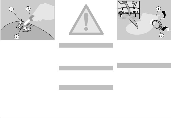
To refuel, proceed as follows:
uRaise the flap (1).
uInsert the key (2) in the tank plug lock
(3).
uTurn the key clockwise, pull and open the fuel flap.
FUEL TANK CAPACITY (reserve included): 21 b
TANK RESERVE: 5 b
 CAUTION
Do not put additives or other substances into the fuel.
If you use a funnel or other similar items, make sure that they are perfectly clean.
 WARNING
Do not fill the tank completely; the maximum fuel level must remain below the lower edge of the filler neck (see figure).
 CAUTION
During the refilling operations, be careful to avoid damaging the inner parts of the tank with the fuel pump.
u Refuel.
After refuelling:
NOTE The cap can be closed only when the key (2) is inserted.
uWith inserted key (2), close the cap by pressing it.
 WARNING
Make sure that the cap is properly closed.
uWithdraw the key (2).
uClose the flap (1).
use and maintenance Pegaso 650 I.E. 25
BRAKE FLUID - recommendations
NOTE This vehicle is provided with front and rear disc brakes, with separate hydraulic circuits.
The following information refers to a single braking system, but is valid for both.
 WARNING
Sudden resistance or clearance problems on the brake lever may be due to troubles in the hydraulic system.
For any doubt regarding the perfect functioning of the braking system and in case you are not able to carry out the usual checking operations, contact your aprilia Official Dealer.
 WARNING
Make sure that the brake discs are neither oily nor greasy, especially after maintenance or checking operations.
Check that the brake cables are neither twisted nor worn out.
Prevent water or dust from accidentally getting into the circuit.
In case maintenance operations are to be performed on the hydraulic circuit, it is advisable to use latex gloves.
If the brake fluid gets in contact with the skin or the eyes, it can cause serious irritations.
 WARNING
Carefully wash the parts of your body that get in contact with the liquid. Consult a doctor or an oculist if the liquid gets in contact with your eyes.
DO NOT DISPOSE OF THE FLUID IN THE ENVIRONMENT.
KEEP AWAY FROM CHILDREN.
 CAUTION
When using the brake fluid, take care not to spill it on the plastic or painted parts, since it can damage them.
26 use and maintenance Pegaso 650 I.E.
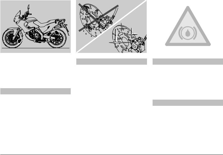
DISC BRAKES
 WARNING
The brakes are the parts that most ensure your safety and for this reason they must always be perfectly working; check them before every trip.
A dirty disc soils the pads, with consequent reduction of the braking efficiency.
Dirty pads must be replaced, while dirty discs must be cleaned with a highquality degreaser.
The brake fluid must be changed every two years by an aprilia Official Dealer.
Use brake fluid of the type specified in the lubricant chart, see p . 93 (LUBRICANT CHART).
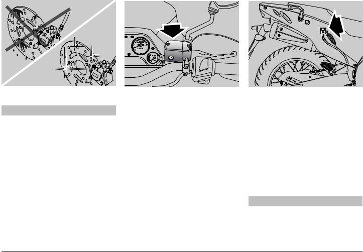
NOTE This vehicle is provided with disc brakes with two, front and rear braking systems having separate hydraulic circuits.
The front braking system is with single disc (left side).
The rear braking system is with single disc (left side).
The following information refers to a single braking system, but is valid for both.
When the disc pads wear out, the level of the fluid decreases to automatically compensate for their wear.
The front brake fluid tank is positioned on the right part of the handlebar, near the front brake lever coupling.
The rear brake reservoir is positioned on the right side of the vehicle, near the rear brake control lever.
NOTE Carry out the maintenance operations halving the intervals indicated, if the vehicle is used in rainy or dusty areas or on uneven surfaces.
Have the brake discs checked by an aprilia Official Dealer after the first 1000 km (625mi) and successively every 6000 km (3750 mi).
Before departure, check the brake fluid level in the reservoirs, see p. 28 (FRONT BRAKE), p. 30 (REAR BRAKE), and the wear of the pads, see p. 71 (CHECKING THE BRAKE PAD WEAR).
Have the brake fluid changed every two years by an aprilia Official Dealer.
 WARNING
Do not use the vehicle if the braking system leaks fluid.
use and maintenance Pegaso 650 I.E. 27
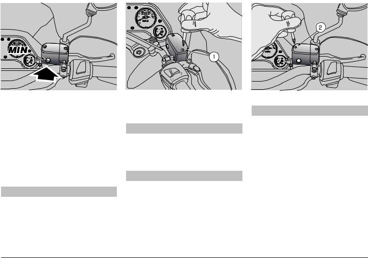
FRONT BRAKE
CHECK
uKeep the vehicle in vertical position and turn the handlebar, so that the fluid contained in the tank is parallel to the brake fluid tank cover.
uMake sure that the fluid level exceeds the “MIN” mark.
MIN= minimum level
If the fluid does not reach at least the “MIN” mark:
 CAUTION
When the disc pads wear out, the level of the fluid decreases progressively to compensate for their wear.
u Check the brake pad wear, see p. 71 (CHECKING THE BRAKE PAD WEAR) and the disc wear.
If the pads and/or the disc do not need replacing, provide for topping up.
TOPPING UP
Carefully read p. 26 (BRAKE FLUID - recommendations).
 CAUTION
The brake fluid may flow out of the tank. Do not operate the front brake lever if the screws (1) and (2) are loose or, most important, if the brake fluid tank cover has been removed.
 CAUTION
Position a cloth under the brake reservoir, in case some fluid should be spilled.
uKeep the vehicle in vertical position and turn the handlebar, so that the fluid contained in the tank is parallel to the brake fluid tank cover.
uUnscrew the screw (1), using a short, cross-tip screwdriver.
u Unscrew the screw (2).
 WARNING
Avoid any prolonged exposure of the brake fluid to the air.
The brake fluid is hygroscopic and when in contact with the air it absorbs its humidity.
Leave the brake fluid tank open ONLY for the time necessary for topping up.
28 use and maintenance Pegaso 650 I.E.
uRaise and remove the cover (3) together with the screws (1) and (2).
uRemove the gasket (4).
 CAUTION
In order not to spill the brake fluid while topping up, do not shake the vehicle.
Do not put additives or other subtances into the fluid.
If you use a funnel or other similar items, make sure that they are perfectly clean.
NOTE In order to reach the “MAX” level, top up until covering the glass (5) completely, with the brake fluid reservoir rim parallel to the ground.
uTop up the reservoir (6) by adding brake fluid, see p. 93 (LUBRICANT CHART), until reaching the correct level.
 CAUTION
Do not exceed the “MAX” level while topping up.
It is advisable to top up until reaching the “MAX” level only with new pads.
Do not reach the “MAX” level with worn out pads, since this will cause a fluid outflow when the pads are changed.
uPut back the gasket (4) in its seat correctly.
uPut back the cover (3).
uScrew and tighten the screw (2).
uScrew and tighten the screw (1).
 WARNING
Check the braking efficiency.
In case of excessive stroke of the brake lever or reduced efficiency of the braking system, contact an aprilia Official Dealer, since it may be necessary to bleed the system.
use and maintenance Pegaso 650 I.E. 29
Loading...