


aprilia
ご覧になればaprilia
APRILIA WOULD LIKE TO THANK YOU
for choosing one of its products. We have compiled this booklet to provide a comprehensive overview of your vehicle's quality features. Please, read it carefully before riding the vehicle for the first time. It contains information, tips and precautions for using your vehicle. It also describes features, details and devices to assure you that you have made the right choice. We believe that if you follow our suggestions, you will soon get to know your new vehicle well and that it will continue to give you satisfactory service for many years to come. This booklet is an integral part of the vehicle and must be handed over to the new owner in the event of sale.
SCARABEO 250 i.e.
Ed. 10 2006
apriliaaprilia
The instructions in this booklet have been compiled primarily to offer a simple and clear guide to using the vehicle; it also describes routine maintenance procedures and regular checks that should be carried out on the vehicle at an Aprilia Dealer or Authorised Workshop. This booklet also contains instructions for simple repairs. Any operations not specifically described in this booklet require the use of special tools and/or particular technical knowledge; for these operations, please take your vehicle to an Aprilia Dealer or Authorised Workshop.
2

|
Personal safety |
|
Failure to completely observe these instruc |
|
tions will result in serious risk of personal |
|
injury. |
|
Safeguarding the environment |
|
Sections marked with this symbol indicate the |
|
correct use of the vehicle to prevent damaging |
|
the environment. |
|
Vehicle intactness |
|
The incomplete or non-observance of these reg |
|
ulations leads to the risk of serious damage to |
|
the vehicle and sometimes even the invalidity |
|
of the guarantee. |
|
The symbols shown above are very important. |
|
They are used to highlight those parts of the |
|
booklet that should be read with particular |
|
care. As you can see, each sign consists of a |
|
different graphic symbol, making it quick and |
" " |
easy to locate the various topics. Before |
|
starting the engine, read this booklet thor |
|
oughly and the "SAFE RIDING" section in par |
|
ticular. Your safety as well as other's does not |
|
only depend on the quickness of your reflexes |
|
and agility, but also on how well you know your |
|
vehicle, the state of maintenance of the vehi |
|
cle itself and your knowledge of the rules for |
|
SAFE RIDING. For your safety, get to know your |
|
vehicle well so as to safely ride and master it |
|
in road traffic IMPORTANT This booklet is an |
|
integral part of the vehicle, and must be handed |
|
to the new owner in the event of sale. |
3
4
|
|
|
|
|
|
|
INDEX |
...................................................... |
7 |
VEHICLE.................................................... |
7 |
................................ |
10 |
Arrangement of the main components....................... |
10 |
.......................................... |
11 |
Dashboard................................................ |
11 |
........................ |
12 |
Analogue instrument panel................................ |
12 |
.................................. |
19 |
Digital lcd display...................................... |
19 |
.............. |
20 |
Setting the total and trip odometers................... |
20 |
/ ....................................... |
21 |
Clock/date display..................................... |
21 |
............................................ |
22 |
Key switch............................................... |
22 |
........................................ |
23 |
Locking the steering wheel............................. |
23 |
............................ |
24 |
Switch direction indicators.............................. |
24 |
.................................................. |
24 |
Horn button.............................................. |
24 |
.......................................... |
25 |
Light switch............................................. |
25 |
........................................ |
25 |
Emergency flashing light button.......................... |
25 |
........................................ |
26 |
Start-up button.......................................... |
26 |
............................................ |
26 |
Engine stop button....................................... |
26 |
.............................................. |
27 |
Fuel tank................................................ |
27 |
............................................ |
28 |
Power supply socket...................................... |
28 |
.................................................. |
28 |
The saddle............................................... |
28 |
.................................................... |
29 |
Identification........................................... |
29 |
............................ |
30 |
Rear top box opening..................................... |
30 |
...................................................... |
31 |
USE........................................................ |
31 |
................................................ |
32 |
Checks................................................... |
32 |
.................................................... |
34 |
Refuelling............................................... |
34 |
............................................ |
37 |
Tyre pressure............................................ |
37 |
...................... |
40 |
Shock absorber adjustment................................ |
40 |
.............................................. |
42 |
Running in............................................... |
42 |
............................................ |
44 |
Starting up the engine................................... |
44 |
............................................ |
51 |
Difficult start up....................................... |
51 |
............................................ |
51 |
Stopping the engine...................................... |
51 |
.......................... |
54 |
Catalytic silencer....................................... |
54 |
................................................ |
55 |
Stand.................................................... |
55 |
5
.............................. |
56 |
................................................ |
58 |
.............................................. |
65 |
.................................. |
66 |
............................ |
67 |
.................................. |
69 |
.................................. |
70 |
...................................... |
73 |
.................................................. |
77 |
................................ |
80 |
................................ |
83 |
............................ |
83 |
........................................ |
84 |
.................................. |
89 |
.............................................. |
92 |
.................................. |
97 |
.................................... |
98 |
................................................ |
99 |
.................................................. |
102 |
.................................. |
104 |
.................................... |
106 |
............................ |
107 |
.................................... |
110 |
................................ |
111 |
.................................... |
111 |
...................... |
112 |
............................................ |
113 |
.......................... |
114 |
...................................... |
117 |
.................................................... |
119 |
.................................................... |
122 |
...................................................... |
125 |
.............................................. |
130 |
.............................. |
133 |
.................................. |
135 |
.............................. |
136 |
........................................ |
145 |
Suggestions to prevent theft............................. |
56 |
Safe driving............................................. |
58 |
MAINTENANCE................................................ |
65 |
Engine oil level......................................... |
66 |
Engine oil level check................................. |
67 |
Engine oil top-up...................................... |
69 |
Engine oil change...................................... |
70 |
Hub oil level............................................ |
73 |
Tyres.................................................... |
77 |
Spark plug dismantlement................................. |
80 |
Removing the air filter.................................. |
83 |
Air filter cleaning...................................... |
83 |
Cooling fluid level...................................... |
84 |
Checking the brake oil level............................. |
89 |
Battery.................................................. |
92 |
Use of a new battery................................... |
97 |
Long periods of inactivity............................... |
98 |
Fuses.................................................... |
99 |
Lamps.................................................... |
102 |
Front light group........................................ |
104 |
Headlight adjustment................................... |
106 |
Front direction indicators............................... |
107 |
Rear optical unit........................................ |
110 |
Rear turn indicators..................................... |
111 |
Number plate light....................................... |
111 |
Helmet compartment lighting bulb......................... |
112 |
Rear-view mirrors........................................ |
113 |
Front and rear disc brake................................ |
114 |
Periods of inactivity.................................... |
117 |
Cleaning the vehicle..................................... |
119 |
Transport................................................ |
122 |
TECHNICAL DATA............................................. |
125 |
Kit equipment............................................ |
130 |
SPARE PARTS AND ACCESSORIES................................ |
133 |
PROGRAMMED MAINTENANCE..................................... |
135 |
Scheduled maintenance table.............................. |
136 |
SPECIAL FITTINGS........................................... |
145 |
6

SCARABEO 250 i.e.
01
Chap. 01 Vehicle
7

1 / 1 Vehicle
01_01
8
Vehicle 1 / 1
01_02
9
1 / 1 Vehicle
|
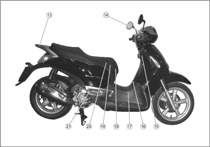
Arrangement of the main |
||
(01_02) |
components (01_02) |
||
|
KEY: |
|
|
1. |
|
1. Expansion tank |
|
2. |
|
2. Coolant expansion tank cap |
|
|
3. Rear brake fluid reservoir |
||
|
|
||
3. |
|
4. Air filter |
|
|
|
||
4. |
|
5. Transmission cover |
|
|
|
||
5. |
|
6. Left passenger footrest |
|
|
|
||
6. |
|
7. Centre stand |
|
|
|
||
7. |
|
8. . Engine oil level/refill cap |
|
|
|
||
8. |
|
9. Side stand |
|
|
|
|
|
9. |
|
10. |
Spark plug |
|
|
||
10. |
|
11. |
Central inspection cover |
|
|
||
11. |
|
12. |
Horn |
|
|
||
12. |
|
13. |
Passenger handgrip |
|
|
||
13. |
|
14. |
Front brake liquid tank |
|
|
||
14. |
|
15. |
Saddle opening switch |
|
|
||
15. |
|
16. |
Fuel tank cap |
|
|
||
16. |
|
17. |
Fuel tank |
|
|
||
17. |
|
18. |
Battery |
|
|
||
18. |
|
19.Secondary fusebox |
|
|
|
||
19. |
20. |
Main fuseboxes |
|
|
|
||
|
|
21. |
Left passenger footrest |
10
(01_03) |
Dashboard (01_03) |
9. ングロック(ON - OFF - LOCKOPEN GLOVE BOXOPEN FUEL TANK
KEY:
1.Electrical controls on the lefthand side of the handlebars
2.Combined brake lever (front and rear)
3.Left rear-view mirror
4.Instruments and gauges
5.Front brake lever
6.Right rear-view mirror
7.Throttle grip
8.Electrical controls on the righthand side of the handlebars
9.Ignition switch / steering lock (ON-OFF - LOCK - OPEN GLOVE BOX - OPEN FUEL TANK)
Vehicle 1 / 1
11

1 / 1 Vehicle
|
|
|
01_03 |
|
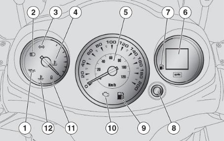
Analogue instrument panel |
||
(01_04) |
(01_04) |
||
|
KEY: |
||
1. |
|
1. |
Red engine oil pressure warning |
2. |
|
light |
|
|
|
||
3. |
|
2. |
Blue high-beam warning light |
|
3. |
Green turn indicator warning |
|
|
|
light |
|
12
4. |
|
4. |
Coolant temperature gauge |
5. |
|
5. |
Speedometer |
6. |
|
6. |
Multifunction LCD panel |
7. |
|
7. |
Fuel gauge |
8. |
MODE |
8. |
MODE button |
9. |
|
9. |
Yellow amber low fuel warning |
10. EFI |
light |
||
|
|
||
11. |
10. EFI warning light |
||
|
11. |
Antitheft warning light (IMMO |
|
BILIZER)
12.
12. Red high coolant temperature warning light
Vehicle 1 / 1
13
1 / 1 Vehicle
|
|
|
01_04 |
|
|
|
INSTRUMENT AND GAUGE DESCRIPTION |
||
|
|
|
|
|
|
|
|
CAUTION |
|
|
«ON» |
WITH THE KEY SET TO «ON» ALL THE PRE- |
||
|
|
INSTALLED WARNING LIGHTS, INSTRUMENT |
||
|
3 |
PANEL LIGHTING AND ALL THE SEGMENT |
||
|
|
IN DISPLAY 3 TURN ON FOR THE FIRST 3 |
||
|
3 |
SECONDS FOR AN INITIAL INSTRUMENT |
||
|
|
|
CHECK. |
|
14

«3» |
Turn indicator warning light "3" |
|||
|
Flashes when the turning indication |
|||
|
is activated |
|||
«2» |
High-beam warning light "2" |
|||
|
Turns on when the front headlamp |
|||
|
high-beam bulb is activated or when |
|||
«1» |
the high-beam light is flashed |
|||
(PASSING). |
||||
|
|
|||
«ON» |
Engine oil pressure warning light |
|||
|
"1" |
|||
LED |
|
|
||
|
Turns on every time the ignition |
|||
|
switch is set to "ON" and the engine |
|||
|
|
has not been started, this tests LED |
||
|
|
|||
|
operation. The warning light should |
|||
|
|
|||
|
|
turn off as soon as the engine is |
||
|
|
started. |
||
|
|
|||
|
|
CAUTION |
||
|
|
|||
|
|
|
||
|
|
|
||
aprilia |
|
|
||
|
IF THE WARNING LIGHT TURNS ON WHILE |
|||
|
|
THE ENGINE IS WORKING PROPERLY, THIS |
||
|
|
MEANS THAT THE OIL PRESSURE IN THE |
||
|
|
CIRCUIT IS NOT ENOUGH. IF THIS OC |
||
|
|
CURS, STOP THE ENGINE AT ONCE AND |
||
|
|
CONTACT AN aprilia Official Dealer. |
||
EFI Electronic fuel injection |
Electronic fuel injection (EFI) |
|||
«10» |
warning light "10" |
|||
«ON» |
Turns on for about three seconds |
|||
3 |
every time the ignition switch is |
|||
Vehicle 1 / 1
15

1 / 1 Vehicle
るとすぐに警告灯は消灯します。
合、直ちにエンジンを停止し、aprilia
set to "ON" and the engine has not been started, this tests the injec tion system operation. The warning light should turn off as soon as the engine is started.
CAUTION
IF THE WARNING LIGHT TURNS ON WHILE THE ENGINE IS WORKING PROPERLY, THIS MEANS THAT THERE IS A FAILURE IN THE ELECTRONIC FUEL INJECTION SYSTEM. IF THIS OCCURS, STOP THE ENGINE AT ONCE AND CONTACT AN aprilia Official Dealer.
ー)"11"
に、盗難を防ぐために点滅します。
"7"
燃料は約2
"9"
Antitheft warning light (immobiliz er) "11"
Only for vehicles fitted with this wiring. When the scooter is off, it flashes as a deterrent against thieves.
Confirms that the antitheft system is on.
Fuel gauge "7"
Shows the approximate fuel level in the tank.
When the needle reaches the red area, there are about 2 litres of fuel left. If this occurs, refill the tank as soon as possible.
Low fuel warning light "9"
16

2
"6"
"5"
"6"
TRIP
"4"
"MIN"
Turns on when there is a 2-litre fuel reserve in the tank.
Digital clock "6"
View time and date in this display.
Speedometer "5"
Shows riding speed
Digital total odometer "6"
Shows the total number of kilometres covered, partial kilometres (TRIP).
Coolant temperature gauge "4"
Shows the approximate temperature of the coolant in the engine. When the needle starts to move away from the "MIN" mark, the temperature is ade quate to ride the scooter. The nor mal operational temperature is when the needle is at central area of the scale. If the needle enters the red area or the warning light turns on, stop the engine and check the cool ant level.
CAUTION
«MAX»
IF THE TEMPERATURE EXCEEDS THE MAX
IMUM ALLOWED «MAX» RED AREA OF THE
SCALE), THE ENGINE CAN BE SERIOUSLY DAMAGED.
Vehicle 1 / 1
17

«12» |
|
Coolant high temperature warning |
|
|
|
light «12» |
|
|
|
Turns on when the coolant tempera |
|
|
|
ture indicator reaches the red area. |
|
|
|
Stop the engine at once and check the |
|
|
|
coolant level. |
|
|
|||
|
|
||
|
|
CAUTION |
|
|
|
|
|
|
|
IF THE TEMPERATURE EXCEEDS THE MAX |
|
|
|
IMUM ALLOWED FOR A LONG TIME, THE |
|
|
|
ENGINE CAN BE SERIOUSLY DAMAGED. |
|
"6" |
|
Multifunction LCD display "6" |
|
|
|
The display can show the digital |
|
|
|
clock, odometer, unit of measure |
|
|
|
ment, trip odometer, scheduled |
|
|
|
maintenance service, fuel level. |
1 / 1 Vehicle
18

|
|
|
Digital lcd display (01_05, |
||
|
|||||
|
(01_05, 01_06) |
|
01_06) |
||
|
|
"1" "ON" |
Turning the ignition key "1" to "ON" |
||
|
|
|
activates all the segments on the |
||
|
|
|
multifunction LCD (this checks com |
||
|
|
|
ponents correct operation) and dis |
||
|
|
|
plays the last function set after |
||
|
|
|
|
switching off the engine. |
|
|
|
|
|
||
|
|
|
|
|
|
|
|
1000km |
|
CAUTION |
|
01_05 |
|
|
|
||
|
10000km |
THE SERVICE ICON IS DISPLAYED ON THE |
|||
|
|
||||
|
|
|
LCD AFTER RIDING THE FIRST 1000 KM |
||
|
|
300km |
AND THEN AFTER EVERY 10000 KM. THE |
||
|
|
|
SERVICE ICON FLASHES FOR ABOUT 5 |
||
|
|
|
SECONDS AFTER THE IGNITION CHECK, |
||
|
|
5 |
300 KM TO THE NEXT SERVICE. ONCE THE |
||
|
|
|
MILEAGE FOR A SERVICE HAS BEEN |
||
|
|
|
REACHED, THE ICON WILL BE STEADILY |
||
|
|
|
ON UNTIL THE SERVICE IS CARRIED OUT. |
||
|
|
|
IF THIS OCCURS TAKE YOUR SCOOTER TO |
||
|
|
aprilia |
AN OFFICIAL APRILIA DEALER TO CARRY |
||
|
|
|
OUT MAINTENANCE OPERATIONS SPECIFIED |
||
|
|
|
|
IN THE SCHEDULED MAINTENANCE TABLE. |
|
MODE"2"
-"3"
-"4"
01_06
Several functions can be selected and viewed on the display using the MODE button "2" on the controls on the left hand side of the handlebar.
The segments of the multifunction LCD display are the following:
-digital clock "3",
-odometer indicator "4",
-unit of measure in km "5",
Vehicle 1 / 1
19

1 / 1 Vehicle
-km "5"
-"6"
-"7"
-"8"
-"9"
-unit of measure indicator in miles "6",
-trip odometer indicator "7",
-scheduled maintenance service in dicator "8",
-fuel gauge "9".
|
|
Setting the total and trip |
|
|
|||
|
(01_07, 01_08) |
odometers (01_07, 01_08) |
|
|
|
DIGITAL ODOMETER |
|
|
|
These are the segments of the digi |
|
|
|
tal odometer functions on the LCD |
|
|
|
display: |
|
|
6 |
Icon to display trip odometer, six |
|
|
"4" km |
digits «4», icon showing unit of |
|
01_07 |
" 5" |
measure in km «5», icon showing unit |
|
"6" |
of measure in miles «6». |
||
|
|||
|
MODE "2" |
Pressing the MODE button «2» dis |
|
|
|
plays in sequence the modes: |
|
|
- |
- Trip odometer |
|
|
- |
- TRIP |
|
|
- |
- Battery voltage |
20
|
|
|
RESETTING THE TRIP ODOMETER |
|
|
|
- MODE "2" |
- Press the MODE button "2" to select |
|
|
|
|
the trip odometer function. |
|
|
|
- MODE "2" 3 |
- Press and hold the MODE button "2" |
|
|
|
|
for more than three seconds. |
|
|
|
|
|
|
|
|
|
|
NOTE |
|
|
|
THIS ONLY RESETS THE FUNCTION DIS |
|
01_08 |
|
|
PLAYED. |
|
|
|
|
|
|
|
|
/ (01_09) |
Clock/date display (01_09) |
||
|
|
|
|
|
|
|
|
|
|
|
CAUTION |
|
|
|
THE CLOCK WILL ONLY BE DISPLAYED |
||
|
|
|
ONLY WHEN THE VEHICLE HAS BEEN |
||
|
|
|
|
STARTED. |
|
|
|
|
Clock adjustment: |
||
|
|
||||
|
|
∙ |
MODE "2" |
|
∙ Press the MODE button "2" to |
|
|
|
|
|
select the TRIP function. |
|
|
∙ MODE "2" 3 |
|
∙ Press and hold the MODE |
|
|
|
|
|
|
button "2" for more than |
|
|
∙ |
|
|
three seconds to activate |
|
|
MODE |
|
the clock adjustment. |
|
|
|
|
"2" |
|
∙ The first adjustment to be |
|
|
∙ |
|
|
made is the hours. Press the |
|
|
MODE |
|
MODE button "2" repeatedly |
|
01_09 |
|
∙ |
"2" 3 |
|
to set the desired hour. |
|
MODE "2" |
|
∙ Pressing the MODE button "2" |
||
|
|
|
|||
|
|
∙ |
|
|
for more than three seconds |
|
|
|
|
activates the minutes ad |
|
|
|
|
3 |
|
justment. |
|
|
|
21 |
|
|
Vehicle 1 / 1

1 / 1 Vehicle
∙To adjust the minutes press the MODE button"2" until the desired minutes are dis played.
∙Once the clock has been ad justed do not press any key for three seconds to leave this function.
NOTE
THE CLOCK CAN BE SET ONLY WHEN THE ENGINE IS OFF OR THE VEHICLE IS AT A STANDSTILL AND WITH OR WITHOUT THE ENGINE RUNNING.
(01_10) |
Key switch (01_10) |
|
«1» |
The ignition switch "1" is found on |
|
|
the right side, near the headstock. |
|
|
|
|
|
|
NOTE |
|
THE KEY ACTIVATES THE IGNITION/ |
|
|
STEERING LOCK SWITCH, THE SADDLE |
|
|
LOCK AND THE GLOVE-BOX LID. |
|
|
|
|
|
|
NOTE |
2 1 |
TWO KEYS ARE SUPPLIED WITH THE VE |
|
|
HICLE (A SPARE ONE). |
|
|
KEEP THE SPARE KEY IN A DIFFERENT |
|
|
PLACE, NOT WITH THE VEHICLE. |
|
22

|
OFF |
OFF: The engine and lights cannot be |
|
|
set to work. The ignition key can be |
|
|
extracted. |
|
ON |
ON: The engine and lights can be set |
|
|
to work. The key cannot be extrac |
|
|
ted. |
|
LOCK |
LOCK: The steering is locked. The |
|
|
engine and lights cannot be set to |
|
|
work. The ignition key can be ex |
01_10 |
|
tracted. |
|
Locking the steering wheel |
||
|
To lock the steering: |
||
∙ |
|
∙ Turn the handlebar fully to |
|
|
|
the left. |
|
∙ |
«LOCK» |
∙ Turn the ignition key to the |
|
|
|
"LOCK"position. |
|
|
|
|
|
|
|
|
CAUTION |
«LOCK» |
AVOIDING LOSING CONTROL OF THE VE |
||
|
HICLE, NEVER TURN THE KEY TO "LOCK" |
||
|
WHILE RIDING. |
||
23
Vehicle 1 / 1
1 / 1 Vehicle
01_11
01_12
|
Switch direction indicators |
|
(01_11) |
|
(01_11) |
«2» |
Move the switch "2" to the left, to |
|
|
indicate a left turn; move the |
|
«2» |
switch "2" to the right, to indicate |
|
|
a right turn.. Pressing the central |
|
|
part of the switch deactivates the |
|
|
turn indicator. While the vehicle is |
|
40 500m |
in motion the system automatically |
|
|
deactivates the turn indicator sys |
|
|
tem after 40 seconds or 500 m. |
|
|
|
|
|
|
NOTE |
"ON" |
ELECTRICAL COMPONENTS FUNCTION ONLY |
|
|
WHEN THE IGNITION KEY IS SET TO "ON" |
|
(01_12) |
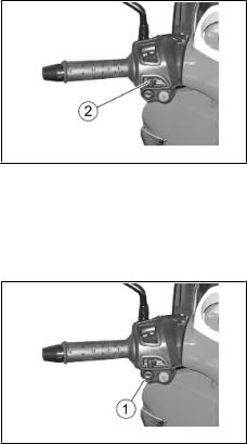
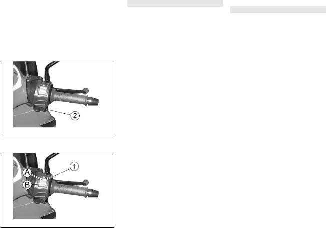
Horn button (01_12) |
|
«1» |
Pressing the button "1" activates |
|
|
the horn. |
|
|
|
|
|
|
NOTE |
"ON" |
ELECTRICAL COMPONENTS FUNCTION ONLY |
|
|
WHEN THE IGNITION KEY IS SET TO "ON" |
|
24
|
|
(01_13) |
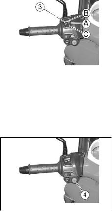
Light switch (01_13) |
|
|
||||
|
|
«3» «B» |
If the light switch "3" is set to |
|
|
|
|
"B", this activates the high-beam |
|
|
|
«A» |
light; if it is set to "A", this ac |
|
|
|
|
tivates the low-beam light. |
|
|
|
«C» |
Turning the light switch to "C" the |
|
|
|
|
high-beam light flashes. |
|
|
|
|
|
|
|
|
|
|
NOTE |
01_13 |
|
"ON" |
ELECTRICAL COMPONENTS FUNCTION ONLY |
|
|
|
|
WHEN THE IGNITION KEY IS SET TO "ON" |
|
|
|
|
|
|
|
|
|
|
NOTE |
|
|
«C» |
ONCE THE LIGHT SWITCH IS RELEASED |
|
|
|
|
FROM THE PASSING MODE IN "C"THE |
|
|
|
|
HIGH-BEAM LIGHT STOPS FLASHING. |
|
(01_14)
«4»
«ON»
4 01_14 «OFF»
Emergency flashing light button (01_14)
Using the HAZARD switch "4" it is possible to activate/deactivate the hazard lights.
ACTIVATION
With the ignition switch in "ON".
Press to activate the four arrows. Now it is possible to turn the ig nition switch to "OFF" and withdraw the key.
DEACTIVATION
Vehicle 1 / 1
25
1 / 1 Vehicle
んで«ON»
を«ON»
Insert the key in the ignition switch and turn it to "ON", press the HAZARD switch again to deactivate the system.
NOTE
ACTIVATE AND DEACTIVATE THE HAZARD LIGHTS ONLY WHEN THE IGNITION KEY IS SET TO "ON"
(01_15) |
Start-up button (01_15) |
|
«2» |
By pressing the starter button «2», |
|
|
the starter motor makes the engine |
|
|
rotate. |
|
|
|
|
|
|
NOTE |
"ON" |
ELECTRICAL COMPONENTS FUNCTION ONLY |
|
|
WHEN THE IGNITION KEY IS SET TO "ON" |
|
01_15
(01_16) |
Engine stop button (01_16) |
|
It acts as an engine cut-off or |
|
emergency stop switch. With the |
«1» «B» RUN |
switch «1» in «B» RUN, it is possible |
|
to start the engine; pressing the |
«A» OFF |
switch when set to «A» OFF will stop |
|
the engine. |
01_16
26

|
|
|
NOTE |
"ON" |
ELECTRICAL COMPONENTS FUNCTION ONLY |
||
|
WHEN THE IGNITION KEY IS SET TO "ON" |
||
|
|
|
|
|
|
|
CAUTION |
|
DO NOT ACTIVATE THE ENGINE STOP |
||
|
SWITCH WHILE RIDING THE VEHICLE. |
||
|
|
|
|
|
|
|
CAUTION |
|
WITH THE ENGINE OFF AND THE IGNITION |
||
«ON» |
SWITCH SET TO «ON» THE BATTERY MAY |
||
|
GET DISCHARGED. WITH THE ENGINE OFF |
||
|
AND AFTER IT STOPS TURN THE IGNITION |
||
«OFF» |
SWITCH TO «OFF». |
||
|
|
||
(01_17) |
Fuel tank (01_17) |
||
|
To reach the fuel tank cap: |
||
∙ |
«1» |
∙ Insert the key "1" into the |
|
|
|
fuel tank compartment lock. |
|
∙ |
|
∙ Turn the key "1" anticlock |
|
«1» |
wise. |
||
|
|
∙ Unscrew the tank cap "2". |
|
∙«2»
01_17
Vehicle 1 / 1
27

1 / 1 Vehicle
|
|
(01_18) |
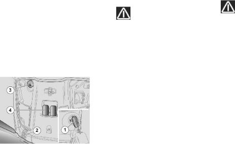
Power supply socket (01_18) |
||
|
|||||
|
|
∙ |
|
∙ There is a 12V socket inside |
|
|
|
|
12V «3» |
of the glovebox "3" and a |
|
|
|
|
«4» |
lever "4" to open the saddle |
|
|
|
|
|
manually.. |
|
|
|
∙ |
12V 180W |
∙ The 12V socket can be used to |
|
|
|
|
|
power equipment with a max |
|
|
|
|
|
imum power of 180 W (mobile |
|
|
|
|
|
telephones, hand lamp, |
|
|
|
|
|
|
etc.). |
01_18 |
|
|
|
|
|
|
|
|
CAUTION |
||
|
|
||||
|
|
USING THIS SOCKET FOR A LONG PERIOD |
|||
|
|
|
|||
|
|
|
CAN RESULT IN A FULLY DISCHARGED |
||
|
|
|
|
|
BATTERY. |
|
(01_19) |
The saddle (01_19) |
|
||
|
- |
- To unlock the saddle automatical |
|
«1» |
ly: press the button "1" on the re |
|
- |
mote control. |
|
|
- To unlock the saddle manually: |
|
- |
open the glovebox. |
|
|
- Pull the lever to unlock the saddle |
|
- |
manually. |
01_19 |
|
- To lock the saddle, lower and press |
|
|
(without force) to trip the lock. |
28

01_20
01_21
|
|
CAUTION |
BEFORE RIDING, MAKE SURE THAT THESADDLE IS CORRECTLY LOCKED INTO PO
SITION.
(01_20, 01_21) |
|
|
Identification (01_20, 01_21) |
||||
|
|
|
|
|
Chassis number |
||
|
The chassis number is stamped on the |
||||||
|
central chassis bar. To read the |
||||||
|
chassis number it will be necessary |
||||||
|
to open the glove-box and remove the |
||||||
|
|
|
snap-on protection. |
||||
|
|
|
|
|
|
|
Chassis |
|
|
|
|
|
|
|
No.: .............................. |
................................... |
|
|
|
|
|
|
................. |
............ |
|
|
|
|
|
||
|
|
|
|
|
Engine number |
||
|
The engine number is stamped near |
||||||
|
the rear shock absorber lower sup |
||||||
|
|
|
|
|
|
port. |
|
|
|
|
|
|
|
|
Engine |
|
|
|
|
|
|
|
No.: .............................. |
................................... |
|
|
|
|
|
|
................. |
............ |
|
|
|
|
|
||
Vehicle 1 / 1
29
1 / 1 Vehicle
|
Write down the chassis and engine |
||
|
numbers in the specific space in |
||
|
this manual. |
||
|
The chassis number can be used to |
||
|
order spare parts. |
||
|
|
|
|
|
|
NOTE |
|
|
|
|
|
|
|
ALTERING IDENTIFICATION NUMBERS CAN |
|
|
BE SERIOUSLY PUNISHED BY LAW, PAR |
||
|
TICULARLY |
MODIFYING THE CHASSIS |
|
|
NUMBER WILL |
IMMEDIATELY INVALIDATE |
|
|
THE WARRANTY. |
||
|
|
Rear top box opening (01_22) |
|
|
|||
|
(01_22) |
Thanks to the glove-box it is not |
|
|
|
|
|
|
|
necessary to carry bulky items with |
|
|
|
you after parking your scooter. |
|
|
|
∙ Insert and press the key |
|
|
∙ |
|
into the lock «1». |
|
|
«1» OFF |
∙ The cover «2» of the glove- |
|
|
box will open automatically. |
|
|
|
|
|
|
∙ |
|
|
|
|
|
|
01_22 |
|
«2» |
|
30
 Loading...