


|
|
|
1300 6 |
RS 125 |
|
|
|
||
|
|
|
00/2006-03 |
|
|
|
|
|
|
www.serviceaprilia.com
workshopmanual
UK
8104976

INTRODUCTION
RS125
INTRODUCTION |
0 |
0 - 1

INTRODUCTION |
|
|
|
|
RS125 |
|
SUMMARY |
|
0.1. |
INTRODUCTION ............................................................................................................................................. |
3 |
0.1.1. |
FOREWORD.......................................................................................................................................... |
3 |
0.1.2. |
REFERENCE MANUALS....................................................................................................................... |
4 |
0.1.3. |
ABBREVIATIONS/SYMBOLS/CONVENTIONS..................................................................................... |
5 |
0 - 2

INTRODUCTION
RS125
0.1.INTRODUCTION
0.1.1.FOREWORD
This manual provides the information required for normal servicing.
This publication is intended for use by aprilia Dealers and their qualified mechanics; many concepts have been omitted on purpose as their inclusion would be superfluous. Since complete mechanical explanations have not been included in this manual, the reader must be familiar with basic notions of mechanics, as well as with basic repair procedures. Without such familiarity, repairs and checks could be ineffective and even hazardous. Since the repair and vehicle check instructions are not exhaustive, special care must be taken to avoid damage and injury. Piaggio & C. S.p.A. undertakes to constantly improve the design of its products and the relevant literature to ensure maximum customer satisfaction. The main technical modifications and changes in repair procedures are communicated to all aprilia dealers and agencies worldwide. Such modifications will be entered in subsequent editions of the manual. Should you need assistance or clarifications about the inspection and repair procedures, please contact the aprilia SERVICE DEPT., they will be glad to give you any information on the matter, or supply you with any detail on updates and technical changes applied to the vehicle.
Piaggio & C. S.p.A. reserves the right to make changes to its products at any time, barring any such changes as may alter the essential features of a product as specified in the relevant manual.
All rights of storage using electronic means, reproduction and total or partial adaptation, whatever the means adopted, are reserved in all countries.
Third parties' products are only mentioned for information purposes, and constitute no engagement. Piaggio & C. S.p.A. is not liable in any way for the performance or use of these products.
First edition: March 2006
Produced and printed by:
VALLEY FORGE DECA
Ravenna , Modena, Torino
DECA s.r.l.
Registered Main Office Via Vincenzo Giardini, 11 48022 Lugo (RA) - Italy - Tel. 0545-216611
Fax 0545-216610 www.vftis.com deca@vftis.spx.com
on behalf of:
Piaggio & C. S.p.A.
via G. Galilei, 1 - 30033 Noale (VE) - Italy Tel. +39 – (0)41 58 29 111
Fax +39 – (0)41 58 29 190 www.aprilia.com www.serviceaprilia.com
0 - 3
INTRODUCTION
RS125
0.1.2.REFERENCE MANUALS
SPARE PARTS CATALOGUE |
|
OWNER’S MANUALS |
|||||||||||||
|
|
|
|
|
|
|
|
|
|
|
|
|
|
|
|
|
aprilia part# (description) |
|
aprilia part# (description) |
|
|||||||||||
3406 |
|
|
|
|
|
|
|
Model Year 1993 |
|
||||||
|
|
|
|
|
|
|
|
8102260 |
|
|
|
|
|
|
|
MANUALI ATTREZZI SPECIALI |
|
|
Model Year 1994 |
|
|||||||||||
|
8102260 |
|
|
|
|
|
|
||||||||
|
|
|
|
|
|
|
|
|
|
|
|
|
|
||
|
|
|
|
|
|
|
|
8102319 |
|
|
|
|
|
|
|
|
aprilia part# (description) |
||||||||||||||
|
|
|
|
|
|
|
|
|
Model Year 1995 |
|
|||||
8202278 |
|
|
|
|
|
||||||||||
|
|
|
|
|
|
|
|
8102476 |
|
|
|
|
|
|
|
|
|
|
|
|
|
|
|||||||||
CHASSIS WORKSHOP MANUAL |
|
8102530 |
|
|
|
|
|
|
|||||||
|
8102543 |
|
|
|
|
|
|
||||||||
|
|
|
|
|
|
|
|
|
Model Year 1996 |
|
|||||
|
aprilia part# (description) |
|
|
|
|
|
|
|
|
||||||
|
|
8102685 |
|
|
|
|
|
|
|||||||
8104972 |
|
|
|
|
|
||||||||||
|
|
|
|
|
|
8102682 |
|
|
|
|
|
|
|||
8104973 |
|
|
|
|
|
|
|
|
|
|
|
|
|||
|
|
|
|
|
|
8102530 |
|
|
|
|
|
|
|||
8104974 |
|
|
|
|
|
|
|
|
|
|
|
|
|||
|
|
|
|
|
|
8102683 |
|
|
|
|
|
|
|||
8104975 |
|
|
|
|
|
|
|
|
|
|
|
|
|||
|
|
|
|
|
|
|
|
|
|
|
|
|
|
||
|
|
|
|
|
|
8102543 |
|
|
|
|
|
|
|||
8104976 |
|
|
|
|
|
|
|
|
|
|
|
|
|||
|
|
|
|
|
|
|
Model Year 1997 |
|
|||||||
|
8CM0101 |
|
|
|
|
|
|
|
|
||||||
|
|
|
|
|
|
|
8102685 |
|
|
|
|
|
|
||
|
|
|
|
|
|
|
|
|
|
|
|
|
|
||
|
|
|
|
|
|
|
|
8102682 |
|
|
|
|
|
|
|
ENGINE TECHNICAL MANUAL |
|
8102683 |
|
|
|
|
|
|
|||||||
|
|
|
|
|
|
|
|
8102530 |
|
|
|
|
|
|
|
|
aprilia part# (description) |
|
8102543 |
|
|
|
|
|
|
||||||
8140880 |
|
|
|
|
|
|
8102752 |
|
|
|
|
|
|
||
8140883 |
|
|
|
|
|
|
|
|
|
|
|
|
|
|
|
|
|
|
|
|
|
8102753 |
|
|
|
|
|
|
|||
8140881 |
|
|
|
|
|
|
|
|
|
|
|
|
|
|
|
|
|
|
|
|
|
|
Model Year 1998 |
|
|||||||
8140882 |
|
|
|
|
|
|
|
|
|||||||
|
|
|
|
|
|
8102685 |
|
|
|
|
|
|
|||
8140884 |
|
|
|
|
|
|
|
|
|
|
|
|
|||
|
|
|
|
|
|
8102682 |
|
|
|
|
|
|
|||
|
8CM0027 |
|
|
|
|
|
|
|
|
|
|
|
|
||
|
|
|
|
|
|
|
8102683 |
|
|
|
|
|
|
||
|
|
|
|
|
|
|
|
|
|
|
|
|
|
||
|
|
|
|
|
|
|
|
8102849 |
|
|
|
|
|
|
|
|
|
|
|
|
|
|
|
8102934 |
|
|
|
|
|
|
|
|
|
|
|
|
|
|
|
|
Model Year 1999 |
|
|||||
|
|
|
|
|
|
|
|
8102821 |
|
|
|
|
|
|
|
|
|
|
|
|
|
|
|
8102937 |
|
|
|
|
|
|
|
|
|
|
|
|
|
|
|
|
|
|
|
|
|
|
|
|
|
|
|
|
|
|
|
8102938 |
|
|
|
|
|
|
|
|
|
|
|
|
|
|
|
8102939 |
|
|
|
|
|
|
|
|
|
|
|
|
|
|
|
|
Model Year 2001 |
|
|||||
|
|
|
|
|
|
|
|
8202248 |
|
|
|
|
|
|
|
|
|
|
|
|
|
|
|
8102821 |
|
|
|
|
|
|
|
|
|
|
|
|
|
|
|
8102937 |
|
|
|
|
|
|
|
|
|
|
|
|
|
|
|
|
|
|
|
|
|
|
|
|
|
|
|
|
|
|
|
8102938 |
|
|
|
|
|
|
|
|
|
|
|
|
|
|
|
8102939 |
|
|
|
|
|
|
|
|
|
|
|
|
|
|
|
|
Model Year 2002 |
|
|||||
|
|
|
|
|
|
|
|
8104465 |
|
|
|
|
|
|
|
|
|
|
|
|
|
|
|
8104466 |
|
|
|
|
|
|
|
|
|
|
|
|
|
|
|
8104467 |
|
|
|
|
|
|
|
|
|
|
|
|
|
|
|
8104468 |
|
|
|
|
|
|
|
|
|
|
|
|
|
|
|
|
Model Year 2006 |
|
|||||
|
|
|
|
|
|
|
|
8104917 |
|
|
|
|
|
|
|
|
|
|
|
|
|
|
|
8104934 |
|
|
|
|
|
|
|
|
|
|
|
|
|
|
|
8104935 |
|
|
|
|
|
|
|
0 - 4

INTRODUCTION
RS125
0.1.3.ABBREVIATIONS/SYMBOLS/CONVENTIONS
#= number
<= less than
>= greater than
≤= less than or equal to
≥= more than or equal to
~= approximately
∞= infinity
°C |
= degrees Celsius (centigrade) |
°F |
= degrees Fahrenheit |
±= plus or minus
a.c |
= alternating current |
A= Ampere
Ah |
= Ampere per hour |
API |
= American Petroleum Institute |
AT |
= high voltage |
AV/DC |
= Anti-Vibration Double Countershaft |
bar |
= pressure measurement unit (1 bar = 100 kPa) |
d.c. |
= direct current |
cc |
= cubic centimetres |
CO |
= carbon monoxide |
CPU |
= Central Processing Unit |
DIN |
= German industrial standards (Deutsche Industrie Norm) |
DOHC |
= Double Overhead Camshaft |
ECU |
= Electronic Control Unit |
rpm |
= revolutions per minute |
HC |
= unburnt hydrocarbons |
ISC |
= Idle Speed Control |
ISO |
= International Standardisation Organisation |
kg |
= kilograms |
kgm |
= kilograms per metre (1 kgm = 10 Nm) |
km |
= kilometres |
km/h |
= kilometres per hour |
kΩ |
= kiloOhm |
kPa |
= kiloPascal (1 kPa = 0.01 bar) |
KS |
= clutch side (from the German "Kupplungsseite") |
kW |
= kilowatt |
ℓ= litres
LAP |
= racetrack lap |
LED |
= Light Emitting Diode |
LEFT |
|
SIDE |
= left side |
m/s |
= metres per second |
max |
= maximum |
mbar |
= millibar (1 mbar = 0.1 kPa) |
mi |
= miles |
MIN |
= minimum |
MPH |
= miles per hour |
MS |
= flywheel side (from the German "Magnetoseite") |
MΩ |
= MegaOhm |
N.A. |
= Not Available |
N.O.M.M. |
= Motor Octane Number |
N.O.R.M. |
= Research Octane Number |
Nm |
= Newton metre (1 Nm = 0.1 kgm) |
Ω= ohm
PICK-UP |
= pick-up |
BDC |
= Bottom Dead Centre |
TDC |
= Top Dead Centre |
PPC |
= Pneumatic Power Clutch |
0 - 5

INTRODUCTION |
|
||
RS125 |
|||
RIGHT |
|
||
|
|
||
|
|
||
SIDE |
= right side |
||
SAE |
= Society of Automotive Engineers |
||
TEST |
= diagnostic check |
||
T.B.E.I. |
= crown-head Allen screw |
||
T.C.E.I. |
= cheese-head Allen screw |
||
T.E. |
= hexagonal head |
||
T.P. |
= flat head screw |
||
TSI |
= Twin Spark Ignition |
||
UPSIDE- |
|
|
|
DOWN |
= inverted fork |
||
V= volt
W |
= watt |
Ø= diameter
0 - 6

GENERAL INFORMATION
RS125
GENERAL INFORMATION |
1 |
1 - 1

GENERAL INFORMATION |
|
|
|
|
RS125 |
|
SUMMARY |
|
1.1. |
GENERAL INFORMATION.............................................................................................................................. |
3 |
1.1.1. |
CONVENTIONS USED IN THE MANUAL ............................................................................................. |
3 |
1.1.2. |
SAFETY WARNINGS............................................................................................................................. |
4 |
1.2. |
GENERAL RULES........................................................................................................................................... |
5 |
1.2.1. |
BASIC SAFETY RULES......................................................................................................................... |
5 |
1.3. |
DANGEROUS ELEMENTS ............................................................................................................................. |
8 |
1.3.1. |
WARNINGS ........................................................................................................................................... |
8 |
1.4. |
RUNNING-IN ................................................................................................................................................. |
12 |
1.4.1. |
RUNNING-IN........................................................................................................................................ |
12 |
1.5. |
VEHICLE IDENTIFICATION.......................................................................................................................... |
13 |
1.5.1. |
POSITION OF THE SERIAL NUMBERS ............................................................................................. |
13 |
1 - 2

GENERAL INFORMATION
RS125
1.1.GENERAL INFORMATION
1.1.1.CONVENTIONS USED IN THE MANUAL
•This manual is divided in sections and subsections, each covering a set of the most significant components. Refer to the index of sections when consulting the manual.
•Unless expressly specified otherwise, assemblies are reassembled by reversing the dismantling procedure.
•The terms "right" and "left" are referred to the rider seated on the vehicle in the normal riding position.
•Motorcycle operation and basic maintenance are covered in the "OWNER'S MANUAL".
In this manual any variants are identified with these symbols:
optional
catalytic version
Full Power version
-all versions
|
250 cc version |
|
200 cc version |
|
125 cc version |
MP |
national certification |
SF |
European certification (EURO 3 limits) |
VERSION: |
|
|
Italy |
Greece |
Malaysia |
United |
Holland |
Chile |
Kingdom |
|
|
Austria |
Switzerland |
Croatia |
Portugal |
Denmark |
Australia |
Finland |
Japan |
United |
|
|
States of |
|
|
America |
Belgium |
Singapore |
Brazil |
Germany |
Slovenia |
South Africa |
France |
Israel |
New |
|
|
Zealand |
Spain |
South |
Canada |
|
Korea |
|
1 - 3
GENERAL INFORMATION
RS125
1.1.2.SAFETY WARNINGS
The following precautionary warnings are used throughout this manual in order to convey the following messages:
Safety warning. This symbol appears, whether in the manual or on the vehicle itself, to indicate a personal injury hazard. Non-compliance with the indications given in the messages preceded by this symbol may result in grave risks for your and other people’s safety and for the vehicle!
DANGER
Indicates a potential hazard which may result in serious injury or even death.
WARNING
Indicates a potential hazard which may result in minor personal injury or damage to the vehicle.
NOTE The word "NOTE" in this manual precedes important information or instructions.
1 - 4
GENERAL INFORMATION
RS125
1.2.GENERAL RULES
1.2.1.BASIC SAFETY RULES
CARBON MONOXIDE
Should it be necessary to perform some operations with the vehicle running, make sure to work outdoors or in a wellaerated room.
Avoid starting the engine indoors.
In case you are working indoors, use a gas exhaust system.
DANGER
Exhaust gases contain carbon monoxide, which is extremely toxic if inhaled and may cause loss of consciousness or even lead to death.
FUEL
DANGER
The fuel used in internal combustion engines is highly flammable and can become explosive under particular conditions.
Refuelling and engine service should take place in a well-ventilated area with the engine stopped. Do not smoke when refuelling or in the proximity of sources of fuel vapours, avoid open flames, sparks and any element that could ignite fuel or provoke explosions.
DO NOT DISPOSE OF FUEL IN THE ENVIRONMENT.
KEEP AWAY FROM CHILDREN.
HIGH-TEMPERATURE COMPONENTS
The engine and the components of the exhaust system become very hot and remain hot for some time after the engine has been stopped.
Before handling these components, wear insulating gloves or wait until the engine and the exhaust system have cooled down.
USED GEARBOX AND FORK FLUIDS
DANGER
Wear latex gloves when servicing.
Gear fluid may cause serious damage to the skin if handled daily and for long periods. Wash your hands carefully after handling gear fluid.
Take it to the filling station where you usually buy it or to an oil salvage centre. Wear latex gloves when servicing.
DO NOT DISPOSE OF FLUID IN THE ENVIRONMENT
KEEP AWAY FROM CHILDREN.
BRAKE FLUID
WARNING
When handling the brake fluid, take care not to spill it on the plastic, rubber or painted parts, since it can damage them. When carrying out the maintenance operations on the braking system, use a clean cloth to cover these parts.
Always wear safety goggles when working on the braking system. The brake fluid is highly irritant. Avoid contact with your eyes.
If the brake fluid gets in contact with your eyes, carefully wash them with fresh water and immediately seek medical advice.
KEEP AWAY FROM CHILDREN.
COOLANT
Coolant contains ethylene glycol that is flammable, under certain conditions. When ignited, ethylene glycol produces invisible flames that might cause burns.
1 - 5
GENERAL INFORMATION
RS125
DANGER
Take care not to spill coolant onto hot engine parts and exhaust system. It may ignite and produce invisible flames.
Wear latex gloves when servicing.
Although toxic, it has a sweet taste that might attract animals. Never leave coolant in open container or in a position easily reachable by animals.
KEEP AWAY FROM CHILDREN.
Do not remove radiator cap when engine is still hot. Coolant is under pressure and might cause burns.
HYDROGEN GAS AND BATTERY ELECTROLYTE
DANGER
The battery electrolyte is a toxic, caustic substance containing sulphuric acid and thus able to cause severe burns in case of contact with the skin.
Always wear tight gloves and protective clothes when handling this fluid. In case of contact with skin, rinse with plenty of fresh water.
Always use a protection for your eyes since even a very small amount of the battery fluid can cause blindness. In the event of contact with your eyes, carefully wash them with water for fifteen minutes and then consult immediately an eye specialist.
Should you accidentally drink some fluid, drink abundant water or milk, then drink magnesia milk or vegetable oil and immediately seek medical advice.
The battery gives off explosive gases and must be kept away from flames and sources of ignition or heat; do not smoke near the battery.
KEEP AWAY FROM CHILDREN.
Battery fluid is corrosive.
Do not spill it, especially on plastic parts.
Make sure that the electrolyte acid is suitable for the type of battery used.
GENERAL PRECAUTIONS AND INFORMATION
Follow these instructions closely when repairing, disassembling or reassembling the motorcycle or its components.
DANGER
Using bare flames is strictly forbidden when working on the motorcycle. Before servicing or inspecting the motorcycle: stop the engine and remove the key from the ignition switch; allow for the engine and exhaust system to cool down; where possible, lift the motorcycle using adequate equipment placed on firm and level ground. Be careful of any parts of the engine or exhaust system which may still be hot to the touch to avoid scalds or burns.
Do not put any vehicle parts into your mouth: vehicle components are not edible and some of them are harmful or even toxic.
Unless expressly specified otherwise, assemblies are reassembled by reversing the dismantling procedure. Where a procedure is cross-referred to relevant sections in the manual, proceed sensibly to avoid disturbing any parts unless strictly necessary. Do not polish matt-painted surfaces with polishing paste.
Never use fuel instead of solvent to clean the motorcycle.
Do not clean any rubber or plastic parts or the seat with alcohol, petrol or solvents. Clean with water and mild detergent.
Always disconnect the battery negative (-) lead before soldering any electrical components.
When two or more persons service the same motorcycle together, special care must be taken to avoid personal injury.
BEFORE DISASSEMBLING ANY COMPONENTS
•Clean off all dirt, mud, and dust and clear any foreign objects from the vehicle before disassembling any components.
•Use the model-specific special tools where specified.
1 - 6
GENERAL INFORMATION
RS125
DISASSEMBLING THE COMPONENTS
-Never use pliers or similar tools to slacken and/or tighten nuts and bolts. Always use the suitable spanner.
-Mark all connections (hoses, wiring, etc.) with their positions before disconnecting them. Identify each connection using a distinctive symbol or convention.
-Mark each part clearly to avoid confusion when refitting.
-Thoroughly clean and wash any components you have removed using a detergent with low flash point.
-Mated parts should always be refitted together. These parts will have seated themselves against one another in service as a result of normal wear and tear and should never be mixed up with other similar parts on refitting.
-Certain components are matched-pair parts and should always be replaced as a set.
-Keep away from heat sources.
REASSEMBLING THE COMPONENTS
DANGER
Never reuse a circlip or snap ring. These parts must always be renewed once they have been disturbed.
When fitting a new circlip or snap ring, take care to move the open ends apart just enough to allow fitment to the shaft.
Make it a rule to check that a newly-fitted circlip or snap ring has located fully into its groove. Never clean a bearing with compressed air.
CAUTION All bearings must rotate freely with no hard spots or noise. Replace any bearings that do not meet these requirements.
-Use ORIGINAL aprilia SPARE PARTS only.
-Use the specified lubricants and consumables.
-Where possible, lubricate a part before assembly.
-When tightening nuts and bolts, start with the largest or innermost nut/bolt and observe a cross pattern. Tighten evenly, in subsequent steps until achieving the specified torque.
-Replace any self-locking nuts, gaskets, seals, circlips or snap rings, O-rings, split pins, bolts and screws which have a damaged thread.
-Lubricate the bearings abundantly before assembly.
-Make it a rule to check that all components you have fitted are correctly in place.
-After repairing the motorcycle and after each service inspection, perform the preliminary checks, and then operate the motorcycle in a private estate area or in a safe area away from traffic.
-Clean all mating surfaces, oil seal edges and gaskets before assembly. Apply a thin layer of lithium grease along the edges of oil seals. Fit oil seals and bearings with the marking or serial number facing outwards (in view).
ELECTRICAL CONNECTORS
To disconnect the electrical connectors, follow the procedures below. Failure to comply with these procedures may lead to irreparable damage to the connector and the wiring as well.
If present, press the special safety hooks.
WARNING
Do not pull cables to disconnect the two connectors.
•Grasp the two connectors and disconnect them by pulling them in the two opposite directions.
•In case of dirt, rust, moisture, etc.., thoroughly clean the inside of the connectors with compressed air.
•Make sure that the cables are correctly fitted inside the connector terminals.
CAUTION The two connectors have just one correct positioning. Make sure to position them in the right direction.
•Then fit the two connectors. Make sure they are correctly coupled (a click will be heard if hooks are present).
TIGHTENING TORQUE SETTINGS
DANGER
Always remember that the tightening torque settings of all wheel, brake, wheel shaft and other suspension parts play a fundamental role to ensure vehicle safety. Make sure that these values are always within the specified limits.
Check fastening parts tightening torque settings at regular intervals. Upon reassembly, always use a torque wrench.
Failure to comply with these recommendations could lead to the loosening and detachment of one of these parts with a consequent locking of the wheel or other serious troubles affecting the vehicle manoeuvrability, and thus the risk of falls and serious injuries or death.
1 - 7

GENERAL INFORMATION
RS125
1.3.DANGEROUS ELEMENTS
1.3.1. WARNINGS
FUEL
DANGER
The fuel used to operate engines is highly flammable and becomes explosive under particular conditions.
Refuelling and engine service should take place in a well-ventilated area with the engine stopped. Do not smoke when refuelling or in the proximity of sources of fuel vapours, avoid open flames, sparks and any element that could ignite fuel or provoke explosions.
Take care not to spill fuel out of the filler, or it may ignite when in contact with hot engine parts.
In the event of accidental fuel spillage, make sure the affected area is fully dry before starting the engine. Fuel expands from heat and when left under direct sunlight.
Never fill the fuel tank up to the brim. Tighten the filler cap securely after each refuelling.
Avoid contact with skin. Do not inhale vapours. Do not swallow fuel. Do not transfer fuel between different containers using a hose.
DO NOT DISPOSE OF FUEL IN THE ENVIRONMENT. KEEP AWAY FROM CHILDREN.
Use only premium grade unleaded petrol, min. O.N. 95 (RON) and 85 (MON).
LUBRICANTS
DANGER
A good lubrication ensures the vehicle safety.
Failure to keep the lubricants at the recommended level or the use of a non-suitable new and clean type of lubricant can lead to the engine or gearbox seizure, thus causing serious accidents, personal injury or even death.
Gear fluid may cause serious damage to the skin if handled daily and for long periods. Wash your hands carefully after use.
Do not dispose of oil in the environment.
Take it to the filling station where you usually buy it or to the supplier.
WARNING
When filling the vehicle with this oil, take care not to spill it out. Immediately clean spilt oil, or it might damage the vehicle paintwork.
In case of contact with oil, the tyres surface will become very slippery, thus becoming a serious danger for your safety.
In case of leaks, do not use the vehicle. Check and trace the cause of leaks and proceed to repair.
ENGINE OIL
DANGER
Engine oil may cause serious damage to the skin if handled daily and for long periods. Wash your hands carefully after use.
Do not dispose of oil in the environment.
Dispose of engine oil through the nearest waste oil reclamation firm or through the supplier. Wear latex gloves when servicing.
FRONT FORK FLUID
DANGER
Front suspension response can be modified to a certain extent by changing damping settings and/or selecting a particular grade of oil. Standard oil viscosity: SAE 20 W. Different oil grades can be selected to obtain a particular suspension response (choose SAE 5W for a softer suspension, 20W for a stiffer suspension).
The two grades can also be mixed in varying solutions to obtain the desired response.
1 - 8
GENERAL INFORMATION
RS125
BRAKE FLUID
NOTE This vehicle is fitted with front and rear disc brakes. Each braking system is operated by an independent hydraulic circuit. The information provided below applies to both braking systems.
DANGER
Do not use the vehicle in case brakes are worn out or do not work properly. The brakes are the parts that most ensure your safety and for this reason they must always be perfectly working. Failure to comply with these recommendations will probably lead to a crash or an accident, with a consequent risk of personal injury or death.
A wet surface reduces brakes efficiency.
DANGER
In case of wet ground the braking distance will be doubled, since both brakes and tyre grip on the road surface are extremely reduced by the water present on the road surface.
Any water on brakes, after washing the vehicle or driving on a wet road surface or crossing puddles or gips, can wet brakes so as to greatly reduce their efficiency.
Failure to comply with these recommendations may lead to serious accidents, with a consequent risk of severe personal injuries or death.
Brakes are critical safety components. Do not ride the vehicle in case brakes are not working at their best.
Check for brakes proper operation before every trip. Brake fluid is irritant. Avoid contact with eyes or skin.
In the event of accidental contact, wash affected body parts thoroughly. In the event of accidental contact with eyes, contact an eye specialist or seek medical advice.
DO NOT RELEASE BRAKE FLUID INTO THE ENVIRONMENT. KEEP AWAY FROM CHILDREN.
When handling brake fluid, take care not to spill it onto plastic or paint-finished parts or they will damage.
DANGER
Do not use any brake fluids other than the specified type. Never mix different types of fluids to top up level, as this will damage the braking system.
Do not use brake fluid from old containers which have been kept open or in storage for long periods. Any sudden changes in play or hardness in the brake levers are warning signs of problems with the hydraulic circuits.
Ensure that the brake discs and brake linings have not become contaminated with oil or grease. This is particularly important after servicing or inspections.
Make sure the brake lines are not twisted or worn.
Prevent accidental entering of water or dust into the circuit. Wear latex gloves when servicing the hydraulic circuit.
DISC BRAKES
DANGER
The brakes are the parts that most ensure your safety
and for this reason they must always be perfectly working; check them before every trip. A dirty disc soils the pads.
Dirty pads must be replaced, while dirty discs must be cleaned with a high-quality degreaser.
Perform the maintenance operations reducing by half the indicated frequency if the vehicle is used in rainy or dusty areas, on uneven surfaces or for racing.
Check brake pads for wear.
When the brake pads wear out, the level of the fluid decreases to automatically compensate for their wear.
The front brake fluid reservoir is located on the right handlebar, near the front brake lever. The rear brake fluid reservoir is located under the right fairing.
Do not use the vehicle if the braking system leaks fluid.
1 - 9
GENERAL INFORMATION
RS125
COOLANT
DANGER
Coolant is toxic when ingested, contact with eyes or skin may cause irritation.
In the event of contact with your skin or eyes, rinse repeatedly with abundant water and seek medical advice. In the event of ingestion, induce vomiting, rinse mouth and throat with abundant water and seek medical advice immediately.
DO NOT RELEASE INTO THE ENVIRONMENT. KEEP AWAY FROM CHILDREN.
DANGER
Take care not to spill coolant onto hot engine parts. It may ignite and produce invisible flames. Wear latex gloves when servicing. Do not ride when coolant is below the minimum level.
Coolant mixture is a 50% solution of water and antifreeze. This is the ideal solution for most operating temperatures and provides good corrosion protection.
This solution is also suited to the warm season, as it is less prone to evaporative loss and will reduce the need for topups.
In addition, less water evaporation means fewer minerals salts depositing in the radiator, which helps preserve the efficiency of the cooling system.
When the outdoor temperature drops below zero degrees centigrade, check the cooling system frequently and add more antifreeze (up to 60% maximum) to the solution, if needed.
Use distilled water in the coolant mixture. Tap water will damage the engine.
Refer to the chart given below and add water with the quantity of antifreeze to obtain a solution with the desired freezing point:
Freezing point C° (-°F) |
Coolant % of volume |
-20° (-4 F°) |
35 |
-30° (-22 F°) |
45 |
-40° (-40 F°) |
55 |
NOTE Coolants have different specifications. The protection degree is written on the label.
WARNING |
|
Use only |
nitrite-free antifreeze and corrosion inhibitors with a freezing point of -35°C |
(-31°F) as a minimum.
DRIVE CHAIN
Check drive chain operation, wear, slack and lubrication.
The vehicle is equipped with an endless chain with a joint link.
WARNING
If too slack, the chain can come off the front or rear sprockets thus leading to serious accidents and damage to the vehicle, with consequent serious personal injury or death.
Do not use the vehicle if the chain slack has not been correctly adjusted.
To check the chain, take it with your hand where it turns on the rear sprocket and pull it as to separate it from the sprocket itself.
If you can move the chain apart of the front sprocket for more than 3 mm (0.125 in), change chain, front and rear sprocket.
DANGER
If not properly maintained, chain can early wear out and lead to the damage of both front and rear sprockets.
Perform chain maintenance operations more frequently if the vehicle is used on dusty or muddy areas.
1 - 10

GENERAL INFORMATION
RS125
TYRES
WARNING
If tyres are excessively inflated, the vehicle will be harder, more difficult and uncomfortable to ride. In addition, the roadworthiness, mainly on wet surfaces and during cornering, will be impaired. Flat tyres (insufficient pressure) can slip on the rim and make you lose the control of the vehicle.
In this case too, both vehicle roadworthiness, manoeuvrability and brake efficiency will be impaired. Tyres changing, repair, maintenance and balancing must be carried out by specialised technicians using suitable equipment.
When new, tyres can have a thin slippery protective coating. Drive carefully for the first kilometres (miles).
Never use rubber treating substances on tyres.
In particular, avoid contact with fluid fuels, leading to a rapid wear. In case of contact with oil or fuel, do not clean but change the tyres.
DANGER
Some of the factory-assembled tyres of this vehicle are provided with wear indicators. There are several kinds of wear indicators.
For more information on how to check the wear, contact your Dealer. Visually check if the tyres are worn and in this case have them changed. If a tyre deflates while driving, stop immediately.
Avoid hard brakings or moves and do not close throttles too abruptly.
Slowly close the throttle grip, move to the edge of the road and use the engine brake to slow down until coming to a halt.
Failure to comply with these recommendations may lead to accidents, with a consequent risk of personal injuries or death.
Do not install tyres with air tube on rims for tubeless tyres and vice versa.
1 - 11
GENERAL INFORMATION
RS125
1.4.RUNNING-IN
1.4.1.RUNNING-IN
Correct engine running-is essential to ensuring proper performance and durability.
If possible, drive on hilly roads and/or roads with many bends, so that the engine, the suspensions and the brakes undergo a more effective running-in.
During running-in, change speed.
In this way the components are first "loaded" and then "relieved" and the engine parts can thus cool down. Even if it is important to stress the engine components during running-in, take care not to exceed.
WARNING
Top acceleration performance is obtained only after covering the first 1500 km (932 mi).
Keep to the following indications:
•Do not open the throttle completely if the speed is low, both during and after running-in.
•Apply the brakes gently and avoid hard, prolonged braking until covering the first 100 km (62 mi). This will allow the brake pad lining to break in properly rubbing on the brake disks.
•During the first 800 km (497 mi), never exceed 5000 rpm (see table).
DANGER
After the first 1000 km (621 mi), have the checking operations indicated in the column "After runningin" carried out by an aprilia Authorised Dealer, see REGULAR SERVICE INTERVALS CHART, in order to avoid hurting yourself or other people and/or damaging the vehicle.
•After the first 800 km (497 mi) and until covering 1600 km (994 mi), drive more briskly, varying speed and using maximum acceleration for just a few seconds, in order to ensure better coupling of the components; never exceed 9000 rpm (see table).
•After the first 1600 km (994 mi), you can expect higher performance from your engine. However, never exceed the maximum rpm allowed (11000 rpm).
Recommended maximum rpm
Mileage Km (mi) |
rpm |
0÷800 (497) |
6000 |
800-1600 (497-994) |
9000 |
Over 1600 (994) |
11000 |
1 - 12
GENERAL INFORMATION
RS125
1.5.VEHICLE IDENTIFICATION
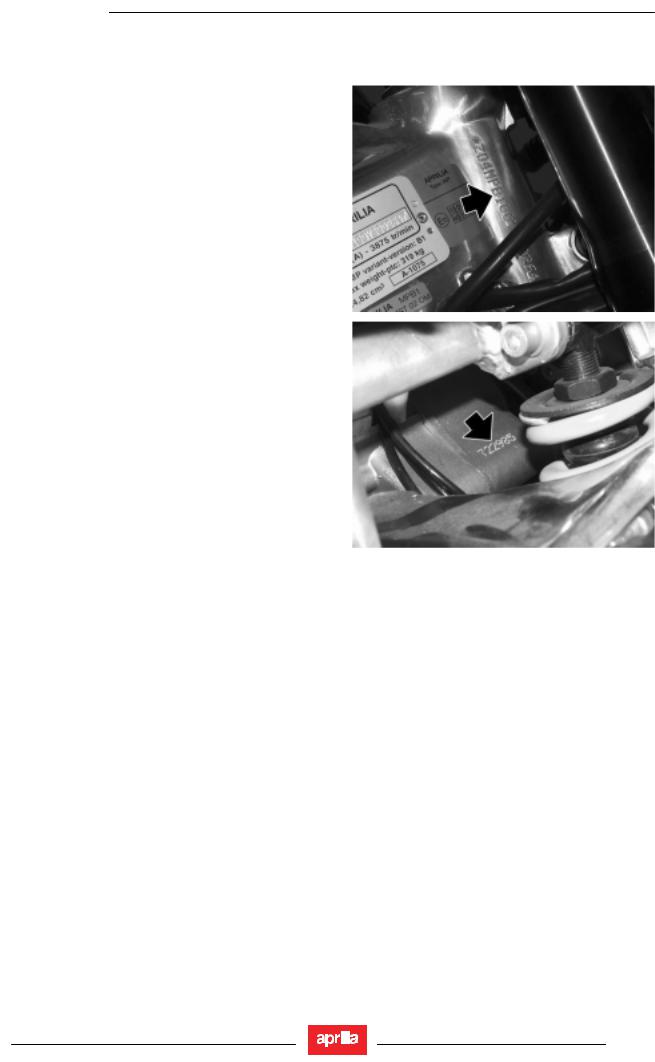
1.5.1.POSITION OF THE SERIAL NUMBERS
These numbers are necessary for vehicle registration.
NOTE Altering the vehicle identification numbers is a legal offence. Altering the frame number invalidates the warranty.
FRAME NUMBER
The frame number is stamped on the right side of the steering column.
ENGINE NUMBER
The engine number is stamped on the rear end, near the shock absorber.
1 - 13
TECHNICAL INFORMATION
RS125
TECHNICAL INFORMATION |
2 |
2 - 1

TECHNICAL INFORMATION
RS125
SUMMARY
2.1. |
TECHNICAL INFORMATION .......................................................................................................................... |
3 |
|
2.1.1. |
|
TECHNICAL DATA ................................................................................................................................ |
3 |
2.1.2. |
|
SCHEDULED MAINTENANCE CHART................................................................................................. |
5 |
2.1.3. |
|
LUBRICANT CHART.............................................................................................................................. |
6 |
2.1.4. |
|
TIGHTENING TORQUE SETTINGS...................................................................................................... |
7 |
2.1.5. |
|
SPECIAL TOOLS................................................................................................................................. |
11 |
2.1.6. |
|
LOCATION OF KEY COMPONENTS .................................................................................................. |
12 |
2.1.7. |
|
LOCATION OF INSTRUMENTS / CONTROLS ................................................................................... |
14 |
2.1.8. |
|
INSTRUMENT PANEL OPERATION................................................................................................... |
16 |
2.1.9. |
|
GEARBOX FLUID ................................................................................................................................ |
20 |
2.1.10. |
CHANGING GEARBOX FLUID............................................................................................................ |
21 |
|
2.1.11. |
CLUTCH ADJUSTMENT...................................................................................................................... |
22 |
|
2.2. |
SCHEDULED MAINTENANCE...................................................................................................................... |
23 |
|
2.2.1. |
|
BRAKE FLUID...................................................................................................................................... |
23 |
2.2.2. |
|
BRAKE PADS ...................................................................................................................................... |
28 |
2.2.3. |
|
LIFTING THE FUEL TANK................................................................................................................... |
29 |
2.2.4. |
|
CLEANING THE AIR FILTER .............................................................................................................. |
30 |
2.2.5. |
|
COOLANT............................................................................................................................................ |
31 |
2.2.6. |
|
REMOVING THE BATTERY ................................................................................................................ |
32 |
2.2.7. |
|
IDLING SPEED ADJUSTMENT ........................................................................................................... |
33 |
2.2.8. |
|
CHOKE ADJUSTMENT ....................................................................................................................... |
34 |
2.2.9. |
|
DRIVE CHAIN ADJUSTMENT ............................................................................................................. |
35 |
2.2.10. |
INSPECTING THE DRIVE CHAIN SLIDER ......................................................................................... |
37 |
|
2 - 2

TECHNICAL INFORMATION
RS125
2.1.TECHNICAL INFORMATION
2.1.1.TECHNICAL DATA
DIMENSIONS
Max. length |
|
|
1955 mm (76.97 in.) |
|
|||
Max. width |
|
|
720 mm (28.34 ) in. |
|
|
||
Max. height (at headlight fairing) |
|
1100 mm (43.31 in.) |
|
||||
Seat height |
|
|
805 mm (31.69 in.) |
|
|
||
Wheelbase |
|
|
1345 mm (52.95 in.) |
|
|||
Minimum ground clearance |
|
163 mm (6.42 in.) |
|
|
|||
Weight in running order (including fluids and fuel) |
137 kg (302.03 lb.) |
|
|
||||
|
|
|
|
|
|
|
|
ENGINE |
|
|
|
|
|
|
|
Type |
|
|
Single-cylinder 2-stroke with reed intake. Separate |
||||
|
|
|
|
lubrication with automatic variable mixer ( 1.0 - 3.0 %). |
|||
Number of cylinders |
|
|
1 |
|
|
|
|
Total displacement |
|
|
124.82 cu cm (7.62 cu. in.) |
|
|||
Bore/stroke |
|
|
54 mm /54.5 mm (2.12 in. /2.14 in.). |
|
|||
Compression ratio |
|
|
12.5 ± 0.5 : 1 |
|
|
|
|
Squish clearance |
|
|
1.5 mm (0.06 in.) |
|
|
||
Engine idling speed |
|
|
1250 ± 100 rpm |
|
|
||
Engine maximum rpm |
|
11000 ± 100 rpm |
|
|
|||
Ignition |
|
|
CDI ignition system with electronic spark timing |
||||
Starting |
|
|
Electric starter |
|
|
||
Clutch |
|
|
Multiplate wet clutch, with control lever on left handlebar |
||||
Gearbox |
|
|
mechanical, 6-speed, with control pedal on left side of |
||||
|
|
|
|
engine |
|
|
|
Gearbox lubrication |
|
|
Splash lubrication |
|
|
||
Lubricating system |
|
|
Separate lubrication with automatic variable mixer ( 1.0 - |
||||
|
|
|
|
1.3 %) |
|
|
|
|
|
|
|
|
|
|
|
CAPACITIES |
|
|
|
|
|
|
|
Fuel (including reserve) |
|
14 l ± 0.5 l (3.70 USgal ± 0.13 USgal) (3.08 gal ± 0.11 gal) |
|||||
Fuel reserve |
|
|
3.5 l (0.92 USgal) (0.77 gal) |
|
|||
Gearbox fluid |
|
|
600 cu cm (36.61 cu. in.) |
|
|||
Gearbox fluid |
|
|
600 cu cm (36.61 cu. in.) |
|
|||
Coolant |
|
|
0.8 l (50% water + 50% antifreeze with ethylene glycol) |
||||
|
|
|
|
(0.21 USgal) (0.17 gal) |
|
||
Mixer oil (reserve included) |
|
1,7 l (0.45 USgal) (0.37 gal) |
|
||||
Mixer oil reserve |
|
|
0.6 l (0.16 USgal) (0.16 gal) |
|
|||
Front fork oil/air |
|
|
440 ± 2,5 cm³ (26.85 ± 0.15 cuin) |
|
|||
Seat |
|
|
2 |
|
|
|
|
Vehicle max. load (rider + passenger + luggage) |
180 kg (396.83 lb.) |
|
|
||||
|
|
|
|
|
|
|
|
TRANSMISSION SYSTEM |
|
|
|
|
|
||
GEAR RATIOS |
|
Ratio |
Primary |
Final |
|
Final ratio |
Total ratio |
|
|
1st |
19/63 = 1: 3.316 |
10/30 = 1: 3.000 |
|
17/40 = 1: 2.353 |
1 : 23.406 |
|
|
2nd |
|
14/29 = 1: 2.071 |
|
|
1 : 16.161 |
|
|
3rd |
|
17/27 = 1: 1.588 |
|
|
1 : 12.391 |
|
|
4th |
|
19/25 = 1: 1.316 |
|
|
1 : 10.266 |
|
|
5th |
|
21/24 = 1: 1.143 |
|
|
1 : 8.916 |
|
|
6th |
|
22/23 = 1: 1.045 |
|
|
1 : 8.156 |
|
|
|
|
|
|
|
|
FUEL SYSTEM |
|
|
|
|
|
|
|
Type |
|
|
Carbureted |
|
|
||
Model |
|
|
DELL’ORTO PHBH 28 |
|
|||
|
|
|
|
|
|
|
|
FUEL SYSTEM |
|
|
|
|
|
|
|
Fuel |
|
|
Premium-grade unleaded petrol, minimum octane rating |
||||
|
|
|
|
95 (RON) and 85 (MON), as per DIN 51 607. |
|||
|
|
|
|
|
|
|
|
2 - 3

|
TECHNICAL INFORMATION |
|
|
|
|
|
|
|
|
|
RS125 |
||||
|
|
|
|
|
|
||
|
|
|
|
|
|
|
|
|
|
|
|
|
|
|
|
|
FRAME |
|
|
|
|
|
|
|
Type |
|
Twin-spar frame with cast and stamped frame sections |
|
|||
|
Steering head angle |
|
25° 30’ |
|
|
|
|
|
Trail |
|
102 mm (4.01 in.) |
|
|
|
|
|
|
|
|
|
|
|
|
|
SUSPENSIONS |
|
|
|
|
|
|
|
Front |
|
hydraulically operated telescopic fork |
|
|||
|
Travel |
|
120 mm (4.72 in.) |
|
|
|
|
|
Rear |
|
Adjustable hydraulic mono-shock absorber |
|
|||
|
Wheel stroke |
|
44.5 mm (1.75 in.) |
|
|
|
|
|
|
|
|
|
|
|
|
|
BRAKES |
|
|
|
|
|
|
|
Front |
|
Disc - Ø |
320 mm (12.60 in.) - with hydraulic transmission |
|
||
|
Rear |
|
Disc - Ø |
220 mm (8.66 in.) - with hydraulic transmission |
|
||
|
|
|
|
|
|
|
|
|
WHEEL RIMS |
|
|
|
|
|
|
|
Type |
|
in light alloy |
|
|
|
|
|
Front |
|
3.00 x 17" |
|
|
|
|
|
Rear |
|
4.00 x 17" |
|
|
|
|
|
|
|
|
|
|
|
|
|
TYRES |
|
|
|
|
|
|
|
Wheel |
Size |
Pressure kPa (bar) |
|
|
|
|
|
Rider only |
Rider and passenger |
|
||||
|
|
|
|
||||
|
Front |
110/70 R 17’’ 54H |
180 (1.8) |
|
180 (1.8) |
|
|
|
|
100/70 ZR 17’’ 54W |
|
|
|
|
|
|
Rear |
150/60 R 17’’ 66 H |
200 (2.0) |
|
230 (2.3) |
|
|
|
|
150/60 ZR 17’’/ 66W |
|
|
|
|
|
|
|
|
|
|
|
|
|
|
IGNITION |
|
|
|
|
|
|
|
Type |
|
CDI |
|
|
|
|
|
Spark advance |
|
12°±2° at 2000 rpm |
|
|
|
|
|
|
|
|
|
|
|
|
|
SPARK PLUG |
|
|
|
|
|
|
|
Standard |
|
NGK R BR10EG |
|
|
|
|
|
Standard |
|
NGK BR8ES |
|
|
|
|
|
Spark plug gap |
|
0.7 - 0.8 mm (0.028 – 0.031 in.) |
|
|||
|
|
|
|
|
|
|
|
|
ELECTRIC SYSTEM |
|
|
|
|
|
|
|
Battery |
|
12 V - B9 - B |
|
|
|
|
|
Fuses |
|
20 - 15 - 7.5 A |
|
|
|
|
|
Generator |
|
12 V – 180 W |
|
|
|
|
|
|
|
|
|
|
|
|
|
BULBS |
|
|
|
|
|
|
|
Low beam (halogen) |
|
12 V - 55 W H11 |
|
|
|
|
|
High beam (halogen) |
|
12 V - 55 W H11 |
|
|
|
|
|
Parking light |
|
12 V - 5 W |
|
|
|
|
|
Turn indicator light |
|
Mini lamps (cannot be replaced) |
|
|||
|
Rear parking light / number plate light / stoplight |
12 V – 5 / 21 W |
|
|
|
||
|
Revolution counter |
|
LED |
|
|
|
|
|
Speedometer light |
|
LED |
|
|
|
|
|
Multifunction display light |
|
LED |
|
|
|
|
|
|
|
|
|
|
|
|
|
WARNING LIGHTS |
|
|
|
|
|
|
|
Neutral |
|
LED |
|
|
|
|
|
Direction indicators |
|
LED |
|
|
|
|
|
High beam lights |
|
LED |
|
|
|
|
|
General alarm |
|
LED |
|
|
|
|
|
Fuel oil reserve |
|
LED |
|
|
|
|
|
|
|
|
|
|
|
|
2 - 4

TECHNICAL INFORMATION
RS125
2.1.2.SCHEDULED MAINTENANCE CHART
|
|
|
|
After running- |
|
Every 4000 km |
|
|
Every 8000 km |
|
|
|
|
|
|
in |
|
|
|
|
|||
|
Component |
|
|
|
(2485 mi) or |
|
|
(4970 mi) or |
|
||
|
|
|
[1000 km |
|
|
|
|
||||
|
|
|
|
|
12 months |
|
|
24 months |
|
||
|
|
|
|
(621 mi)] |
|
|
|
|
|||
|
|
|
|
|
|
|
|
|
|
||
|
Rear shock absorber |
|
- |
|
|
- |
|
|
1 |
|
|
|
Battery - Clamp tightening |
|
|
1 |
|
|
1 |
|
|
- |
|
|
Spark plug |
|
|
1 |
|
|
1 |
|
|
3 |
|
|
Carburettor |
|
1 |
|
2 |
|
|
- |
|
||
|
Transmission and control cables |
|
1 |
|
1 |
|
|
- |
|
||
|
RAVE control unit |
|
1 |
|
- |
|
|
4 |
|
||
|
Wheel truing |
|
- |
|
1 |
|
|
- |
|
||
|
Steering bearings and steering clearance |
|
1 |
|
1 |
|
|
- |
|
||
|
Wheel bearings |
|
- |
|
1 |
|
|
- |
|
||
|
Brake discs |
|
1 |
|
1 |
|
|
- |
|
||
|
Air filter |
|
|
- |
|
|
2 |
|
|
3 |
|
|
Vehicle operation |
|
1 |
|
1 |
|
|
- |
|
||
|
Clutch clearance |
|
|
4 |
|
|
4 |
|
|
- |
|
|
Braking systems |
|
1 |
|
1 |
|
|
- |
|
||
|
Cooling system |
|
1 |
|
1 |
|
|
- |
|
||
|
Light system |
|
|
1 |
|
|
1 |
|
|
- |
|
|
Brake fluid |
|
|
1 |
|
|
1 |
|
|
- |
|
|
Brake fluid |
|
|
|
|
|
every year: |
3 |
|
|
|
|
Coolant |
|
|
|
|
|
every 2 years: 3 |
|
|
||
|
Coolant |
|
|
|
|
|
Every 1500 km (935 mi): 1 |
|
|||
|
Mixer oil level |
|
|
|
|
|
Every 500 km (310 mi): 1 |
|
|||
|
Gearbox fluid |
|
|
3 |
|
|
1 |
|
|
Every 12000 km |
|
|
|
|
|
|
|
|
(7456 mi): 3 |
|
|||
|
|
|
|
|
|
|
|
|
|
|
|
|
Fork fluid and oil seal |
|
|
|
|
Every 12000 km (7456 mi): 3 |
|||||
|
Headlight beam direction - operation |
|
|
- |
|
|
1 |
|
|
- |
|
|
Piston and piston rings |
|
|
|
|
Every 8000 km (4970 mi): 1 |
|||||
|
|
|
|
|
Every 16000 km (9941 mi): 3 |
||||||
|
|
|
|
|
|
||||||
|
Engine idling speed |
|
|
4 |
|
|
4 |
|
|
- |
|
|
Odometer drive |
|
- |
|
- |
|
|
1 |
|
||
|
Wheels/Tyres and inflation pressure |
|
1 |
|
1 |
|
|
- |
|
||
|
Wheels/Tyres and inflation pressure |
|
|
|
|
|
Every 1000 km (621 mi): 1 |
|
|||
|
Tightening of nuts and bolts |
|
1 |
|
1 |
|
|
- |
|
||
|
Exhaust silencer (except catalytic version) |
|
2 |
|
2 |
|
|
- |
|
||
|
Front suspension |
|
|
|
|
|
|
|
|
1 |
|
|
Mixer oil reserve LED light |
|
1 |
|
1 |
|
|
- |
|
||
|
Drive chain tension and lubrication |
|
|
|
|
|
Every 500 km (310 |
mi): 1 |
|
||
|
Final transmission (chain, rear sprocket and |
front |
- |
|
1 |
|
|
- |
|
||
|
sprocket) |
|
|
|
|
|
|||||
|
|
|
|
|
|
|
|
|
|
|
|
|
Fuel hose |
|
- |
|
1 |
|
|
every 4 years: 3 |
|||
|
Braking system lines |
|
- |
|
1 |
|
|
every 4 years: 3 |
|||
|
Mixer oil pipe |
|
- |
|
1 |
|
|
every 4 years: 3 |
|||
|
Clutch wear |
|
- |
|
1 |
|
|
- |
|
||
|
Front and rear brake wear |
|
|
1 |
|
|
Every 2000 |
km (1242 mi): 1 |
|
||
|
Exhaust valve |
|
1 |
|
2 + 4 |
|
|
- |
|
||
1 = check and clean, adjust, lubricate or change, if necessary; 2 = clean; |
|
3 = change; 4 = adjust. |
|
|
|||||||
Carry out the maintenance operations more frequently if you use the vehicle in rainy and dusty areas, on uneven ground or for racing.
( ) = OPERATIONS THAT CAN BE CARRIED OUT BY THE USER (**) = Check every two weeks or at the specified intervals.
2 - 5

TECHNICAL INFORMATION
RS125
2.1.3.LUBRICANT CHART
LUBRICANT |
|
|
|
PRODUCT |
|
|
Gearbox fluid |
|
|
|
RECOMMENDED: |
F.C., SAE 75W - 90. |
|
|
|
|
|
As an alternative to recommended oils, top brand oils meeting or exceeding |
||
|
|
|
|
A.P.I. GL-4 specifications can be used. |
|
|
Mixer oil |
|
|
|
RECOMMENDED: |
MAX 2T COMPETITION. |
|
|
|
|
|
As an alternative to recommended oil, top brand oils meeting or exceeding |
||
|
|
|
|
ISO-L-ETC ++,A.P.I. TC ++ specifications can be used. |
||
Fork fluid |
|
|
|
RECOMMENDED: Fork fluid F.A. 5W or |
F.A. 20W. |
|
|
|
|
|
When you wish to obtain an intermediate response between those offered |
||
|
|
|
|
by F.A. 5W and |
F.A. 20W oils, you may mix the different products as |
|
|
|
|
|
follows: |
|
|
|
|
|
|
SAE 10W = F.A. 5W 67% of volume, + |
F.A. 20W 33% of volume. |
|
|
|
|
|
SAE 15W = F.A. 5W 33% of volume, + |
F.A. 20W 67% of volume. |
|
|
|
|
|
|
|
|
Bearings |
and |
other |
RECOMMENDED: |
AUTOGREASE MP |
|
|
lubrication points |
|
|
|
As an alternative to recommended grease, use top brand rolling bearing |
||
|
|
|
|
grease that will resist a temperature range of -30 °C to +140 °C (-22 °F to |
||
|
|
|
|
+284 °F), with dripping point 150 °C to 230 °C (302 °F to 446 °F), high |
||
|
|
|
|
corrosion protection, good resistance to water and oxidisation. |
||
Battery terminals |
|
|
|
Use neutral grease or Vaseline. |
|
|
Aerosol lubricant for chains |
|
|
RECOMMENDED: |
CHAIN SPRAY. |
|
|
|
|
|
|
|
||
Brake fluid |
|
|
|
RECOMMENDED: |
F.F., DOT 5 (DOT 4 compatible). |
|
|
|
|
|
|||
|
|
|
|
CAUTION Use new brake fluid only. Do not mix different makes or types of |
||
|
|
|
|
oil without having checked bases compatibility. |
|
|
|
|
|
|
|
|
|
Engine coolant |
|
|
|
RECOMMENDED: ECOBLU – 40°C (- 40 °F). |
||
|
|
|
|
|||
|
|
|
|
NOTE Use only nitrite-free antifreeze and corrosion inhibitors with a |
||
|
|
|
|
freezing point of - 35°C (- 31°F) as a minimum. |
|
|
|
|
|
|
|
|
|
2 - 6

TECHNICAL INFORMATION
RS125
2.1.4.TIGHTENING TORQUE SETTINGS
Check and tighten as required after the first 1000 km (621 mi) and every 4000 km (2485 mi) or 12 months afterwards.
WARNING
The fasteners listed in the chart must be tightened to the specified torque using a torque wrench and applying LOCTITE ® where specified.
Safety-related items are in brackets ( ).
).
Notes:
L243 = secure with Loctite® 243
Lub= lubricate
|
DESCRIPTION |
|
|
|
|
Q.ty |
|
|
Screw / nut |
|
|
|
|
Nm |
|
|
Kgm |
|
|
Note |
|
||
|
FRAME |
|
|
|
|
|
|
|
|
|
|
|
|
|
|
|
|
|
|
|
|
|
|
|
Head to frame |
|
|
|
|
4 |
|
|
Socket-head screw M8x20 |
|
|
22 |
|
|
2.2 |
|
|
|
|
||||
|
Seat frame to frame fastener |
|
|
|
4 |
|
|
Socket-head screw M8x25 |
|
|
22 |
|
|
2.2 |
|
|
|
|
|||||
|
Instrument panel subframe to |
2 |
|
|
Hex flange screw M6x45 |
10 |
|
1.0 |
|
|
|
|
|||||||||||
|
frame |
|
|
|
|
|
|
|
|
|
|
|
|||||||||||
|
|
|
|
|
|
|
|
|
|
|
|
|
|
|
|
|
|
|
|
|
|
|
|
|
Filter box fastener onto seat frame |
2 |
|
|
Hex flange screw M6x20 |
5 |
|
0.5 |
|
|
|
|
|||||||||||
|
Splitter to frame |
|
|
|
2 |
|
Hex flange screw M6x20 |
10 |
|
1.0 |
|
|
|
|
|||||||||
|
|
|
|
|
|
|
|
|
|
|
|
|
|
|
|
|
|
|
|
|
|
|
|
|
FOOTRESTS |
|
|
|
|
|
|
|
|
|
|
|
|
|
|
|
|
|
|
|
|
|
|
|
Rider footrest bracket |
|
|
4 |
|
Socket-head screw M8x30 |
22 |
|
2.2 |
|
|
|
|
||||||||||
|
Passenger footrest bracket |
|
|
4 |
|
Socket-head screw M8x20 |
22 |
|
2.2 |
|
|
|
|
||||||||||
|
Rider footrest guard |
|
|
|
2 |
|
|
Allen |
crowned-head |
screw |
3 |
|
0.3 |
|
|
|
|
||||||
|
|
|
|
|
|
M5x12 |
|
|
|
|
|
|
|
|
|||||||||
|
|
|
|
|
|
|
|
|
|
|
|
|
|
|
|
|
|
|
|
|
|
||
|
Upper rider footrest bracket |
|
|
2 |
|
Socket-head screw M8x35 |
22 |
|
2.2 |
|
|
|
|
||||||||||
|
|
|
|
|
|
|
|
|
|
|
|
|
|
|
|
|
|
|
|
|
|
|
|
|
STAND |
|
|
|
|
|
|
|
|
|
|
|
|
|
|
|
|
|
|
|
|
|
|
|
Stand connection |
|
|
|
2 |
|
Hex flange screw M8x35 |
22 |
|
2.2 |
|
|
|
|
|||||||||
|
Side stand pin |
|
|
|
1 |
|
M10X1.25 |
|
|
|
10 |
|
1.0 |
|
|
|
|
||||||
|
Side stand pin short nut |
|
|
1 |
|
M10X1.25 |
|
|
|
25 |
|
2.5 |
|
|
|
|
|||||||
|
Stand switch fixing screw |
|
|
1 |
|
Hex flange screw |
M6x16 |
10 |
|
1.0 |
|
L243 |
|||||||||||
|
|
|
|
|
|
|
|
|
|
|
|
|
|
|
|
|
|
|
|
|
|
|
|
|
SWINGING ARM |
|
|
|
|
|
|
|
|
|
|
|
|
|
|
|
|
|
|
|
|
|
|
|
Brake line / chain slider clamp |
5 |
|
|
Allen |
crowned-head |
|
screw |
2 |
|
0.2 |
|
|
|
|
||||||||
|
|
|
M5x12 |
|
|
|
|
|
|
|
|
||||||||||||
|
|
|
|
|
|
|
|
|
|
|
|
|
|
|
|
|
|
|
|
|
|
||
|
Rear lower mudguard |
|
|
2 |
|
|
Hex flange screw |
M6x16 |
5 |
|
0.5 |
|
|
|
|
||||||||
|
Swinging arm pivot fastener |
|
|
|
1 |
|
|
|
|
|
|
|
|
100 |
|
|
10.0 |
|
|
|
|
||
|
Ring nut adjusting bush |
|
|
|
1 |
|
|
|
|
|
|
|
|
12 |
|
|
1.2 |
|
|
lub |
|
||
|
Chain slider |
|
|
|
1 |
|
|
Allen |
crowned-head |
screw |
2 |
|
0.2 |
|
|
|
|
||||||
|
|
|
|
|
|
M5x16 |
|
|
|
|
|
|
|
|
|||||||||
|
|
|
|
|
|
|
|
|
|
|
|
|
|
|
|
|
|
|
|
|
|
||
|
Swinging arm pivot adjustment |
|
|
1 |
|
|
|
|
|
|
|
|
35 |
|
|
3.5 |
|
|
|
|
|||
|
|
|
|
|
|
|
|
|
|
|
|
|
|
|
|
|
|
|
|
|
|
||
|
FRONT SUSPENSION |
|
|
|
|
|
|
|
|
|
|
|
|
|
|
|
|
|
|
|
|
||
|
Stanchion tubes onto fork yoke |
|
|
4 |
|
|
Socket-head screw M8x30 |
|
|
25 |
|
|
2.5 |
|
|
|
|
||||||
|
Stanchion tubes onto top yoke |
|
|
2 |
|
|
Socket-head screw M8x30 |
|
|
25 |
|
|
2.5 |
|
|
|
|
||||||
|
|
|
|
|
|
|
|
|
|
|
|
|
|||||||||||
|
Steering column nut |
|
|
|
|
1 |
|
|
|
|
|
|
|
|
80 |
|
|
8.1 |
|
|
|
|
|
|
Ring nut |
|
|
|
|
1 |
|
|
|
|
|
|
|
|
7 |
|
|
0.7 |
|
|
|
|
|
|
|
|
|
|
|
|
|
|
|
|
|
|
|
|
|
|
|
|
|
|
|
||
|
REAR SUSPENSION |
|
|
|
|
|
|
|
|
|
|
|
|
|
|
|
|
|
|
|
|
||
|
Shock absorber to frame fastener |
|
|
1 |
|
|
Socket-head screw M10x80 |
|
|
50 |
|
|
5.1 |
|
|
lub |
|
||||||
|
Single connecting rod to frame |
|
|
1 |
|
|
Socket-head screw M10x120 |
|
|
50 |
|
|
5.1 |
|
|
lub |
|
||||||
|
|
|
|
|
|
|
|
|
|
|
|
||||||||||||
|
Double |
connecting |
rod |
to single |
|
1 |
|
|
Hex flange screw M10x75 |
|
|
50 |
|
|
5.1 |
|
|
lub |
|
||||
|
|
|
|
|
|
|
|
|
|
|
|||||||||||||
|
connecting rod |
|
|
|
|
|
|
|
|
|
|
|
|
|
|||||||||
|
|
|
|
|
|
|
|
|
|
|
|
|
|
|
|
|
|
|
|
|
|
||
|
Double connecting rod to swinging arm |
|
|
1 |
|
|
Socket-head |
|
screw |
|
|
80 |
|
|
8.1 |
|
|
lub |
|
||||
|
|
|
|
|
|
|
|||||||||||||||||
|
|
|
|
|
|
|
|
|
|
M12X78.5 |
|
|
|
|
|
|
|
|
|
|
|
|
|
|
Shock |
absorber to |
double |
connecting |
|
|
1 |
|
|
Hex flange screw M8x40 |
|
|
25 |
|
|
2.5 |
|
|
lub |
|
|||
|
|
|
|
|
|
|
|
|
|
|
|
||||||||||||
|
rod |
|
|
|
|
|
|
|
|
|
|
|
|
|
|
||||||||
|
|
|
|
|
|
|
|
|
|
|
|
|
|
|
|
|
|
|
|
|
|
|
|
|
|
|
|
|
|
|
|
|
|
|
|
|
|
|
|
|
|
|
|
|
|
|
|
2 - 7

|
TECHNICAL INFORMATION |
|
|
|
|
|
|
|
|
|
|
|
|
|
|
|
|
|
|
|
|
|
|
|
|
|
|
|
|
|
|
RS125 |
|||
|
|
|
|
|
|
|
|
|
|
|
|
|
|
|
|
|
|
|
|
|
|
|
|
|
|
|
|
|
|
|
|
|
|
|
|
|
|
|
|
|
|
|
|
|
|
|
|
|
|
|
|
||
|
DESCRIPTION |
|
|
Q.ty |
|
|
Screw / nut |
|
|
Nm |
|
|
Kgm |
|
Note |
||
|
ENGINE |
|
|
|
|
|
|
|
|
|
|
|
|
|
|
|
|
|
Head to frame screw |
|
|
4 |
|
|
Socket-head screw M8x20 |
|
|
22 |
|
|
2.2 |
|
|
|
|
|
Upper front engine mount |
|
1 |
|
|
Socket-head screw M10x120 |
|
|
50 |
|
|
5.1 |
|
|
|
||
|
Lower front engine mount |
|
1 |
|
|
Hex flange screw M10x205 |
|
|
50 |
|
|
5.1 |
|
|
|
||
|
Rear engine mount |
|
1 |
|
|
Socket-head screw M8x85 |
|
|
22 |
|
|
2.2 |
|
|
|
||
|
Gearbox connecting rod |
|
|
1 |
|
|
Hex flange screw M6x20 |
|
|
10 |
|
|
1.0 |
|
|
|
|
|
Lower rear fastener |
|
|
1 |
|
|
Hex flange screw M8x70 |
|
|
22 |
|
|
2.2 |
|
|
|
|
|
Sprocket cover fastener |
|
|
2 |
|
|
Socket-head screw M6x20 |
|
|
5 |
|
|
0.5 |
|
|
|
|
|
|
|
|
|
|
|
|
|
|
|
|
|
|
|
|
|
|
|
FILTER BOX |
|
|
|
|
|
|
|
|
|
|
|
|
|
|
|
|
|
Filter box |
2 |
|
Hex flange screw M6x25 |
|
5 |
|
0.5 |
|
|
|
||||||
|
|
|
|
|
|
|
|
|
|
|
|
|
|
|
|
|
|
|
EXHAUST SYSTEM |
|
|
|
|
|
|
|
|
|
|
|
|
|
|
|
|
|
Muffler central section |
1 |
|
|
Socket-head screw M8x70 |
|
22 |
|
2.2 |
|
|
|
|||||
|
(bracket) |
|
|
|
|
|
|
|
|||||||||
|
|
|
|
|
|
|
|
|
|
|
|
|
|
|
|
||
|
Muffler to bracket |
1 |
|
Socket-head screw M8x50 |
|
22 |
|
2.2 |
|
|
|
||||||
|
Clamp onto silent block |
1 |
|
Socket-head screw M8x12 |
|
22 |
|
2.2 |
|
|
|
||||||
|
Silent blocks to supports |
3 |
|
|
Nut M8 |
|
|
22 |
|
2.2 |
|
|
|
||||
|
|
|
|
|
|
|
|
|
|
|
|
|
|
|
|
|
|
|
COOLING SYSTEM |
|
|
|
|
|
|
|
|
|
|
|
|
|
|
|
|
|
Water bleed valve |
1 |
|
|
Allen |
crowned-head |
screw |
2 |
|
0.2 |
|
|
|
||||
|
|
|
|
|
|
|
5.5x15.9 |
|
|
|
|
|
|
|
|
|
|
|
|
|
|
|
|
|
|
|
|
|
|
|
|
|
|
|
|
|
FRONT WHEEL |
|
|
|
|
|
|
|
|
|
|
|
|
|
|
|
|
|
Front wheel shaft fastener |
|
1 |
|
|
Wheel shaft |
|
|
80 |
|
|
8.1 |
|
|
|
||
|
Stanchion tubes to wheel shaft |
|
4 |
|
|
Socket-head screw M6x30 |
|
|
10 |
|
|
1.0 |
|
|
|
||
|
|
|
|
|
|
|
|
|
|
|
|
|
|
|
|
|
|
|
REAR WHEEL |
|
|
|
|
|
|
|
|
|
|
|
|
|
|
|
|
|
Rear wheel shaft fastener |
|
1 |
|
|
Shaft nut |
|
|
|
100 |
|
|
10.0 |
|
|
|
|
|
|
|
|
|
|
|
|
|
|
|
|
|
|
|
|
|
|
|
FRONT BRAKE |
|
|
|
|
|
|
|
|
|
|
|
|
|
|
|
|
|
Oil tank mount to pump |
|
|
1 |
|
|
Hex flange screw M6x12 |
|
|
7 |
|
|
0.7 |
|
|
|
|
|
Oil tank to mount |
1 |
|
Hex flange screw M6x25 |
|
7 |
|
0.7 |
|
|
|
||||||
|
Oil tank to mount |
1 |
|
Nut M6 |
|
|
7 |
|
0.7 |
|
|
|
|||||
|
Front brake disc |
|
6 |
|
|
Hex flange screw M8x20 |
|
|
22 |
|
|
2.2 |
|
|
|
||
|
Brake calliper |
|
|
2 |
|
|
Allen |
crowned-head |
screw |
|
50 |
|
|
5.1 |
|
|
|
|
|
|
|
|
|
|
|
|
|||||||||
|
|
|
|
|
|
|
M10x55 |
|
|
|
|
|
|
|
|
|
|
|
Brake line to calliper |
|
|
1 |
|
|
Special screw |
|
|
20 |
|
|
2.0 |
|
|
|
|
|
|
|
|
|
|
|
|
|
|
|
|
|
|
|
|
|
|
|
REAR BRAKE |
|
|
|
|
|
|
|
|
|
|
|
|
|
|
|
|
|
Hose clamp to swinging arm |
2 |
|
Hex flange screw M5x12 |
|
2 |
|
0.2 |
|
|
|
||||||
|
Rear brake oil tank |
1 |
|
Hex flange screw M6x16 |
|
7 |
|
0.7 |
|
|
|
||||||
|
Rear brake disc |
6 |
|
Hex flange screw M6x20 |
|
10 |
|
1.0 |
|
|
|
||||||
|
Brake line to calliper |
1 |
|
|
Special screw |
|
20 |
|
2.0 |
|
|
|
|||||
|
Adjuster screw on brake lever |
1 |
|
Hex flange screw M6x25 |
|
10 |
|
1.0 |
|
|
|
||||||
|
Rear brake pump and |
2 |
|
|
Hex flange screw M6x35 |
|
10 |
|
1.0 |
|
|
|
|||||
|
guard |
|
|
|
|
|
|
|
|||||||||
|
|
|
|
|
|
|
|
|
|
|
|
|
|
|
|
||
|
Brake calliper |
2 |
|
Hex flange screw M6x30 |
|
22 |
|
2.2 |
|
|
|
||||||
|
|
|
|
|
|
|
|
|
|
|
|
|
|
|
|
|
|
|
HANDLEBAR AND CONTROLS |
|
|
|
|
|
|
|
|
|
|
|
|
|
|
|
|
|
Anti-vibration weights |
2 |
|
Socket-head screw M6x50 |
|
10 |
|
1.0 |
|
|
|
||||||
|
Control casings to handlebar |
4 |
|
|
Socket-head screw M6 |
|
3 |
|
0.3 |
|
|
|
|||||
|
|
|
|
|
|
|
|
|
|
|
|
|
|
|
|
|
|
2 - 8

|
|
|
|
|
|
|
|
|
|
|
TECHNICAL INFORMATION |
||||||
RS125 |
|
|
|
|
|
|
|
|
|||||||||
|
|
|
|
|
|
|
|
|
|
|
|
|
|
|
|
||
|
|
|
|
|
|
|
|
|
|
|
|
|
|
|
|
|
|
|
|
|
|
|
|
|
|
|
|
|
|
|
|
|
|
||
|
DESCRIPTION |
|
Q.ty |
|
|
Screw / nut |
|
|
Nm |
|
|
Kgm |
|
Note |
|
||
|
ELECTRICAL COMPONENTS |
|
|
|
|
|
|
|
|
|
|
|
|
|
|
||
|
Battery box mount |
4 |
|
|
Hex flange screw M5x25 |
|
5 |
|
0.5 |
|
|
|
|||||
|
bracket |
|
|
|
|
|
|
|
|||||||||
|
|
|
|
|
|
|
|
|
|
|
|
|
|
|
|||
|
Expansion tanks to battery |
1 |
|
Hex flange screw M6x16 |
|
5 |
|
0.5 |
|
|
|
||||||
|
Horn fastener |
1 |
|
Hex flange screw M8x16 |
|
22 |
|
2.2 |
|
|
|
||||||
|
Battery box mount to frame |
4 |
|
Socket-head screw M8x30 |
|
22 |
|
2.2 |
|
|
|
||||||
|
Undertail and oil tank fastener |
5 |
|
|
Hex flange screw M5x16 |
|
2 |
|
0.2 |
|
|
|
|||||
|
Fuse box to frame |
2 |
|
Hex flange screw M8x20 |
|
5 |
|
0.5 |
|
|
|
||||||
|
Fitment to headlight |
4 |
|
|
Crowned cheese-headed screw |
1.5 |
|
0.15 |
|
|
|
||||||
|
|
|
|
|
|
|
M4x16 |
|
|
|
|
|
|
|
|
|
|
|
Coil to holder |
2 |
|
Hex flange screw M6x45 |
|
10 |
|
1.0 |
|
|
|
||||||
|
Voltage regulator fastener |
2 |
|
Hex flange screw M6x25 |
|
10 |
|
1.0 |
|
|
|
||||||
|
Tail light fastener |
2 |
|
|
Allen |
crowned-head |
screw |
2 |
|
0.2 |
|
|
|
||||
|
|
|
|
M5x16 |
|
|
|
|
|
|
|||||||
|
|
|
|
|
|
|
|
|
|
|
|
|
|
|
|
|
|
|
Battery box mount |
2 |
|
Hex flange screw M6x12 |
|
5 |
|
0.5 |
|
|
|
||||||
|
|
|
|
|
|
|
|
|
|
|
|
|
|
|
|
||
|
TANKS |
|
|
|
|
|
|
|
|
|
|
|
|
|
|
||
|
Tank front fastener |
2 |
|
Socket-head screw M6x50 |
|
7 |
|
0.7 |
|
|
|
||||||
|
Tank rear fastener |
2 |
|
Socket-head screw M6x70 |
|
7 |
|
0.7 |
|
|
|
||||||
|
Tank filler plug fastener |
2 |
|
Socket-head screw M5x30 |
|
5 |
|
0.5 |
|
|
|
||||||
|
Tank filler plug / spacer |
2 |
|
Socket-head screw M5x16 |
|
3 |
|
0.3 |
|
|
|
||||||
|
Fuel cock to fuel tank |
|
2 |
|
|
Tie 16 - 25 |
|
|
2 |
|
|
0.2 |
|
|
|
||
|
|
|
|
|
|
|
|
|
|
|
|
|
|
|
|
||
|
SEAT |
|
|
|
|
|
|
|
|
|
|
|
|
|
|
||
|
Passenger seat fastener |
2 |
|
|
Allen |
crowned-head |
screw |
7 |
|
0.7 |
|
|
|
||||
|
|
|
|
M6x16 |
|
|
|
|
|
|
|||||||
|
|
|
|
|
|
|
|
|
|
|
|
|
|
|
|
|
|
|
Passenger grab strap |
2 |
|
|
Allen |
crowned-head |
screw |
5 |
|
0.5 |
|
|
|
||||
|
|
|
|
M6x20 |
|
|
|
|
|
|
|||||||
|
|
|
|
|
|
|
|
|
|
|
|
|
|
|
|
|
|
|
Passenger grab strap |
2 |
|
|
Nut M6 |
|
|
5 |
|
0.5 |
|
|
|
||||
|
|
|
|
|
|
|
|
|
|
|
|
|
|
|
|
||
|
COMPLEMENTARY ACCESSORIES |
|
|
|
|
|
|
|
|
|
|
|
|
|
|
||
|
Number plate extension |
6 |
|
|
Self-tapping screw 3.9x14 |
|
5 |
|
0.5 |
|
|
|
|||||
|
Turn indicators |
2 |
|
|
Nut M8 |
|
|
8 |
|
0.8 |
|
|
|
||||
|
Number plate holder |
3 |
|
|
Allen |
crowned-head |
screw |
9 |
|
0.9 |
|
|
|
||||
|
|
|
M5x16 |
|
|
|
|
|
|
||||||||
|
|
|
|
|
|
|
|
|
|
|
|
|
|
|
|
|
|
|
|
|
|
|
|
|
|
|
|
|
|
|
|
|
|
||
|
CHAIN |
|
|
|
|
|
|
|
|
|
|
|
|
|
|
||
|
Chain tensioner wheel to footrest bracket |
1 |
|
Socket-head screw M8x70 |
|
25 |
|
2.5 |
|
|
|
||||||
|
|
|
|
|
|
|
|
|
|
|
|
|
|
|
|
||
|
FRONT BODYWORK |
|
|
|
|
|
|
|
|
|
|
|
|
|
|
||
|
RH-LH deflector to upper side fairing |
5 |
|
PLSTC S/TAP screw 3.9x14 |
1 |
|
0.1 |
|
|
|
|||||||
|
Windscreen to fairing front piece |
3 |
|
Allen |
crowned-head |
screw |
3 |
|
0.3 |
|
|
|
|||||
|
|
|
|
|
|
|
M4x16 |
|
|
|
|
|
|
|
|
|
|
|
Mudguard to fork |
5 |
|
Allen |
crowned-head |
screw |
5 |
|
0.5 |
|
|
|
|||||
|
|
|
|
|
|
|
M5x16 |
|
|
|
|
|
|
|
|
|
|
|
|
|
|
|
|
|
|
|
|
|
|
|
|
|
|
|
|
2 - 9

|
TECHNICAL INFORMATION |
|
|
|
|
|
|
|
|
|
|
|
|
|
|
|
RS125 |
||
|
|
|
|
|
|
|
|
|
|
|
|
|
|
|
|
|
|
|
|
|
|
|
|
|
|
|
|
|
|
|
DESCRIPTION |
Q.ty |
Screw / nut |
Nm |
|
Kgm |
|
Note |
|
|
CENTRE BODYWORK |
|
|
|
|
|
|
|
|
|
|
|
|
|
|
|
|
|
|
|
Upper RH-LH fairing to frame |
2 |
Allen crowned-head screw M5x16 |
2 |
|
0.2 |
|
|
|
|
Upper RH-LH fairing to front piece |
2 |
S/TAP crowned cheese-hd screw 4.2X16 |
1 |
|
0.1 |
|
|
|
|
RH-LH fairing to upper side fairing |
8 |
Allen crowned-head screwM5x16 2 |
2 |
|
0.2 |
|
|
|
|
RH-LH fairing to lwr fastening plate |
2 |
Allen crowned-head screwM5x16 2 |
2 |
|
0.2 |
|
|
|
|
RH-LH inner fairing to upper side fairing |
8 |
PLSTC S/TAP crowned chesse-hd screw |
1 |
|
0.1 |
|
|
|
|
|
|
4.2X16 |
|
|
|
|
|
|
|
Lower cowl to frame (radiator |
2 |
Allen crowned-head screw M5x16 |
2 |
|
0.2 |
|
|
|
|
connection plate) |
|
|
|
|
|
|
||
|
|
|
|
|
|
|
|
|
|
|
|
|
|
|
|
|
|
|
|
|
REAR BODYWORK |
|
|
|
|
|
|
|
|
|
RH-LH seat frame cover to seat frame |
8 |
Allen crowned-head screw M5x16 |
10 |
|
1 |
|
|
|
|
RH-LH tail guard to tail light |
4 |
Allen crowned-head screw M5x16 |
2 |
|
0.2 |
|
|
|
|
RH-LH tail guard to seat frame cover |
2 |
Allen crowned-head screw M5x16 |
2 |
|
0.2 |
|
|
|
|
Seat frame lower cover to seat frame |
2 |
Allen crowned-head screw M5x16 |
2 |
|
0.2 |
|
|
|
|
Seat frame lower cover to tail guard |
10 |
S/TAP crownedcheese-hd screw 4.2X16 |
1 |
|
0.1 |
|
|
|
|
Number plate holder to seat frame lower |
3 |
S/TAP crownedcheese-hd screw 4.2X14 |
2 |
|
0.2 |
|
|
|
|
cover |
|
|
|
|
|
|
||
|
|
|
|
|
|
|
|
|
|
|
Number plate holder to seat frame lower |
2 |
Allen crowned-head screw M5x16 |
10 |
|
1 |
|
|
|
|
cover |
|
|
|
|
|
|
||
|
|
|
|
|
|
|
|
|
|
|
Splashguard to number plate holder |
6 |
S/TAP crowned cheese-hd screw 4.2X14 |
10 |
|
1 |
|
|
|
|
|
|
|
|
|
|
|
|
|
Steel / aluminium fixing screws with similar elastic moduli
Screw |
Nm |
Kgm |
M4 |
3 |
0.3 |
M5 |
6 |
0.6 |
M6 |
12 |
1.2 |
M8 |
25 |
2.5 |
M10 |
50 |
5.0 |
M12 |
80 |
8.0 |
2 - 10
 Loading...