


 Loading...
NVR2
6/12-CHANNEL HD NETWORK VIDEO RECORDER – HDMI – ONVIF – EAGLE EYES – PUSH VIDEO
HD NETWERK VIDEORECORDER MET 6/12 KANALEN – HDMI – ONVIF
– EAGLE EYES – PUSH VIDEO
ENREGISTREUR VIDÉO RÉSEAU HD À 6/12 CANAUX - HDMI - ONVIF - EAGLE EYES – PUSH VIDEO
GRABADOR DE VÍDEO EN RED DE ALTA DEFINICIÓN DE 6/12 CANALES - HDMI - ONVIF - EAGLE EYES – PUSH VIDEO
6/12-KANAL HOCHAUFLÖSENDER NETZWERK-VIDEOREKORDER - HDMI - ONVIF - EAGLE EYES – PUSH VIDEO
QUICK INSTALLATION GUIDE |
3 |
KORTE HANDLEIDING |
13 |
GUIDE D'INSTALLATION RAPIDE |
23 |
GUÍA RÁPIDA |
33 |
SCHNELLEINSTIEG |
43 |

NVR2
V. 01 – 04/03/2013 |
2 |
©Velleman nv |

NVR2
QUICK INSTALLATION GUIDE
1.Introduction
To all residents of the European Union
Important environmental information about this product
This symbol on the device or the package indicates that disposal of the device after its lifecycle could harm the environment. Do not dispose of the unit (or batteries) as unsorted municipal waste; it should be taken to a specialized company for recycling. This device should be returned to your distributor or to a local recycling service. Respect the local environmental rules.
If in doubt, contact your local waste disposal authorities.
Thank you for choosing Velleman! Please read the manual thoroughly before bringing this device into service. If the device was damaged in transit, don't install or use it and contact your dealer.
2.Safety Instructions
Keep this device away from children and unauthorized users.
Risk of electroshock when opening the cover. Touching live wires can cause life-threatening electroshocks.
Always disconnect mains power when device not in use or when servicing or maintenance activities are performed. Handle the power cord by the plug only.
3.General Guidelines
Refer to the Velleman® Service and Quality Warranty on the last pages of this manual.
Indoor use only. Keep this device away from rain, moisture, splashing and dripping liquids. Never put objects filled with liquid on top of or close to the device.
Keep this device away from dust and extreme temperatures. Make sure the ventilation openings are clear at all times. For sufficient air circulation, leave at least 1” (±2.5 cm) in front of the openings.
Protect this device from shocks and abuse. Avoid brute force when operating the device.
Familiarise yourself with the functions of the device before actually using it.
All modifications of the device are forbidden for safety reasons. Damage caused by user modifications to the device is not covered by the warranty.
Only use the device for its intended purpose. Using the device in an unauthorised way will void the warranty.
Damage caused by disregard of certain guidelines in this manual is not covered by the warranty and the dealer will not accept responsibility for any ensuing defects or problems.
Keep this manual for future reference.
DO NOT use this product to violate privacy laws or perform other illegal activities.
4.Features
high definition recording
recording throughput: 12 channel mode: 720 x 480 pixels: ± 360 IPS
1280 x 720 pixels: ± 120 IPS 6 channel mode: 720 x 480 pixels: ± 180 IPS
1280 x 720 pixels: ± 180 IPS
1920 x 1080: ± 90 IPS
mobile surveillance via free EagleEyes software on iPhone, iPad, and Android
mobile phone connection via GPRS, 3G data or Wi-Fi
GUI (Graphical User Interface) display and USB mouse
high compatibility and offsite backup: compatible with all major IP cameras that are ONVIF certified
V. 01 – 04/03/2013 |
3 |
©Velleman nv |
NVR2
added NAS function to back up all kind of IP cameras on the internet
works with free Central Management System (CMS) software for
offsite backup
local and remote control completely independent
HDMI video output resolution up to 1080P
optional monitor: MONSCA8
adapter: PAC916T
HDMI cable: Professional or Premium
optional hard disk: HD500GB/S, HD1TB/S, HD2TB/S
USB mouse: included
IR remote control: included
IP cameras: suitable: CAMIP11, CAMIP12
also compatible with: CAMIP9, CAMIP13, CAMIP14 & ONVIF cameras
compatible with powerline adapter: EM8017, EM8024, EM8025, EM8026
optional router: EM4542, EM4553, EM4570, PCRT1
5.Overview
Refer to the illustrations on page 2 of this manual.
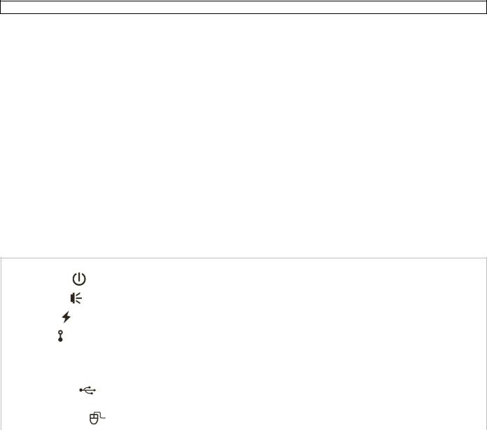
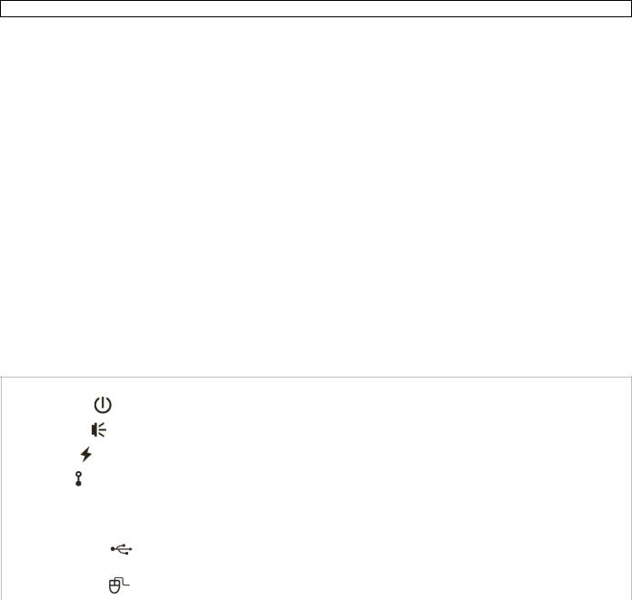
Front panel
1 |
POWER |
LED indicator: the NVR is switched on |
|
|
|
||
|
|
|
|
2 |
ALARM |
LED indicator: an alarm event occurs |
|
|
|
||
|
|
|
|
3 |
WAN |
LED indicator: the NVR is connected to internet |
|
|
|
||
|
|
|
|
4 |
LAN |
LED indicator: the NVR is connected to the LAN |
|
|
|
||
|
|
|
|
5 |
SATA |
LED indicator: SATA hard disk is active |
|
|
|
|
|
6 |
HDD1/HDD2 |
LED indicator: up to two hard disks are installed in the NVR and connected well |
|
|
|
|
|
|
|
Insert a compatible USB flash drive for video backup. |
|
7 |
USB port |
Note: For the list of compatible USB flash drives, refer to the full manual on the |
|
|
|
CD-ROM. |
|
|
|
|
|
8 |
mouse port |
Insert a mouse (included). |
|
|
|
||
|
|
|
|
|
|
||
Back panel |
|
||
|
|
|
|
|
|
|
|
9 |
RS485 |
RS 485 port |
|
|
|
|
|
10 |
SATA |
Connect an external SATA hard disk |
|
|
|
|
|
|
HDMI video output |
Connect to a monitor that supports high-definition video output (HDMI port). |
|
11 |
Note: Use an appropriate adapter (not incl.) to connect a monitor with VGA or |
||
port |
|||
|
composite connectors. |
||
|
|
||
|
|
|
|
12 |
LAN |
Connect to local IP cameras via an 8P8C (RJ45) network cable. |
|
|
|
|
|
13 |
WAN |
Connect to internet via an 8P8C (RJ45) network cable |
|
|
|
|
|
14 |
AUDIO OUT |
Connect to an amplifier audio line-in. |
|
|
|
|
|
15 |
DC 19V IN |
Connect to the power supply adapter (incl.). |
|
|
|
|
|
6.Installing the hard disk drive
1.Obtain a suitable hard disk (not included), type ESATA (Serial Advanced Technology Attachment). The hard disk must be formatted.
2.Make sure to unplug the device from the mains before servicing and do not touch any electronic circuitry to avoid electrostatic discharge.
3.Loosen the screws and remove the top cover.
4.Find the hard disk bracket in the NVR, and insert the hard disk in the bracket.
5.With the PCB side facing up, connect the hard disk to the power connector and the data connector.
6.Fasten the hard disk with the supplied screws, two for each side.
V. 01 – 04/03/2013 |
4 |
©Velleman nv |

NVR2
7.To install a second hard disk, find the supplied hard disk brackets in the package, and fix them to the NVR base.
8.With the PCB side facing up, connect the hard disk to the power connector and data connector.
9.Place the hard disk in the brackets and fasten it with the supplied screws, two for each side.
10.Put the top cover back in place and fasten the screws.
7.Connection Diagram
Note: To ensure that automatic configuration works well, connect and switch on the IP cameras first. Only then switch on the NVR.
You can up to 12 IP cameras.
Refer to the illustrations on page 2 of this manual.
A |
IP camera |
E |
monitor supporting high-definition video |
|
|
|
|
B |
Modem |
F |
19VDC power supply adapter |
|
|
|
|
C |
Router |
G |
NVR back panel |
|
|
|
|
D |
8P8C (RJ45) network cable |
H |
hub/switch |
|
|
|
|
Connecting the IP camera (plug and play)
1.Connect the camera to a hub/switch.
2.Wait until the camera is configured automatically and the images appear on the monitor.
8.Information and Panels on the Monitor
Refer to the illustrations on page 2 of this manual.
16 |
NVR status |
|
|
|
|
|
|
|
|
|
|
key lock |
|
key unlock |
|
|
|
|
|
|
|
channel lock |
|
channel unlock |
|
|
|
|
|
|
|
USB flash drive / device connected |
|
no USB device connected |
|
|
|
|
|
|
|
timer recording on |
|
timer recording off |
|
|
|
|
|
|
|
overwrite on |
|
overwrite off |
|
|
|
|
|
|
|
sequence mode on |
|
sequence mode off |
|
|
|
|
|
|
|
PTZ mode on |
|
PTZ mode off |
|
|
|
|
|
|
|
CPU load |
|
|
|
|
|
|
|
V. 01 – 04/03/2013 |
5 |
©Velleman nv |

|
|
|
|
NVR2 |
|
|
|
|
|
|
|
|
|
|
|
|
network status |
|
|
|
|
||
|
|
|
|
|
|
|
|
|
|
(WAN) internet connected |
|
|
(WAN) internet disconnected |
||
|
|
|
|
|
|
|
|
|
|
(WAN) local connection |
|
|
|
|
|
|
|
|
|
|
|
|
|
|
|
(LAN) auto mode – Mbit/s |
|
|
(LAN) auto mode – Gbit/s |
||
|
|
|
|
|
|
|
|
|
|
(LAN) DHCP / static IP mode |
|
|
(LAN) camera disconnected |
||
|
|
|
|
|
|
|
|
17 |
available hard disk space |
|
|
|
|
||
|
|
|
|
|
|
|
|
18 |
channel status |
|
|
|
|
||
|
|
|
|
|
|
|
|
|
|
auto search on |
|
|
|
auto search off |
|
|
|
|
|
|
|
|
|
|
|
live audio on |
|
|
|
audio off |
|
|
|
|
|
|
|
|
|
|
|
audio playback on |
|
|
|
audio playback off |
|
|
|
|
|
|
|
|
|
|
|
original size |
|
|
|
fit to screen |
|
|
|
|
|
|
|
|
|
|
|
recording |
|
|
|
human detection event |
|
|
|
|
|
|
|
|
|
|
|
alarm event |
|
|
|
motion event |
|
|
|
|
|
|
|
|
|
|
|
live information |
|
|
|
playback information |
|
|
|
|
|
|
|
|
|
19 |
quick operation |
|
|
|
|
||
|
|
|
|
||||
|
|
Click to show the power-off panel to stop or reboot the system. |
|||||
|
|
|
|
||||
|
|
Click to show the channel switch panel and select the channel you want. |
|||||
|
|
|
|
|
|||
|
|
Switch to the channel you want first, then click |
to enter zoom mode. Click and drag the |
||||
|
|
red frame on the bottom left of the screen to move to the area where you want to zoom in. |
|||||
|
|
|
|
||||
|
|
Click to enter PTZ mode and show the PTZ camera control panel. |
|||||
|
|
|
|
||||
|
|
Click to open the IP search window and check the connection status of each channel. |
|||||
|
|
|
|
|
|
|
|
20 |
main menu |
|
|
|
|
||
|
|
|
|
|
|||
|
|
QUICK START |
|
Click to set the status display, image settings, and date & time. |
|||
|
|
|
|
|
|||
|
|
SYSTEM |
|
Click to set the system configuration. |
|||
|
|
|
|
|
|
|
|
|
|
EVENT |
|
Click to enter the event search menu. |
|||
|
|
INFORMATION |
|
||||
|
|
|
|
|
|
|
|
|
|
|
|
|
|||
|
|
ADVANCED CONFIG |
|
Click to set CONNECTION, CAMERA, DETECTION, ALERT, NETWORK, |
|||
|
|
|
DISPLAY, RECORD and NOTIFY. |
||||
|
|
|
|
||||
|
|
|
|
|
|||
|
|
SCHEDULE SETTING |
|
Click to set the recording timer. |
|||
|
|
|
|
|
|
|
|
21 |
playback panel |
|
|
|
|
||
|
|
|
|
||||
|
|
fast forward |
|
Click to fast forward at 4 to 32 times normal speed. |
|||
|
|
|
|
|
|||
|
|
fast rewind |
|
Click to fast rewind at 4 to 32 times normal speed. |
|||
|
|
|
|
|
|||
|
|
|
|
Click to play the latest recorded video clip. Click again to pause. |
|||
|
|
play/pause |
|
In pause mode, click |
once to go one frame forward, or to go |
||
|
|
|
|
||||
|
|
|
|
one frame backward. |
|
|
|
|
|
|
|
|
|||
|
|
stop |
|
Click to stop the video playback. |
|||
|
|
|
|
|
|
|
|
V. 01 – 04/03/2013 |
6 |
©Velleman nv |

|
|
|
NVR2 |
|
|
|
|
|
|
slow playback |
Click once to play at 1/4 normal speed, click twice for 1/8 normal |
|
|
speed. |
|
|
|
|
|
|
|
|
|
|
|
|
Click to jump to the next/previous one-hour time interval (for |
|
|
previous/next hour |
example, 11:00 ~ 12:00 or 14:00 ~ 15:00) and start playing the |
|
|
|
earliest video clip recorded during this hour. |
|
|
|
|
|
|
quick search |
Click to enter the quick search menu. |
|
|
|
|
8.2Key lock / unlock
To lock or unlock NVR local operation, click  (lock) or
  (unlock) on the NVR status panel [15]. When you unlock NVR local operation, the system asks you to enter a user name and password.
Note: The default user name and password are “admin”. Different user types have different access rights to NVR functions. For details, refer to the full manual on the CD-ROM.
9.Configuration of camera on LAN Port plug and play
Note: This configuration method applies to ETS cameras.
9.1Automatic Configuration
The NVR will automatically configure the IP address of an ETS camera connected by LAN if:
The default IP configuration method of the camera is DHCP.
The camera is powered on before the NVR is powered on.
If not, you can configure the IP address of your camera manually as described further below.
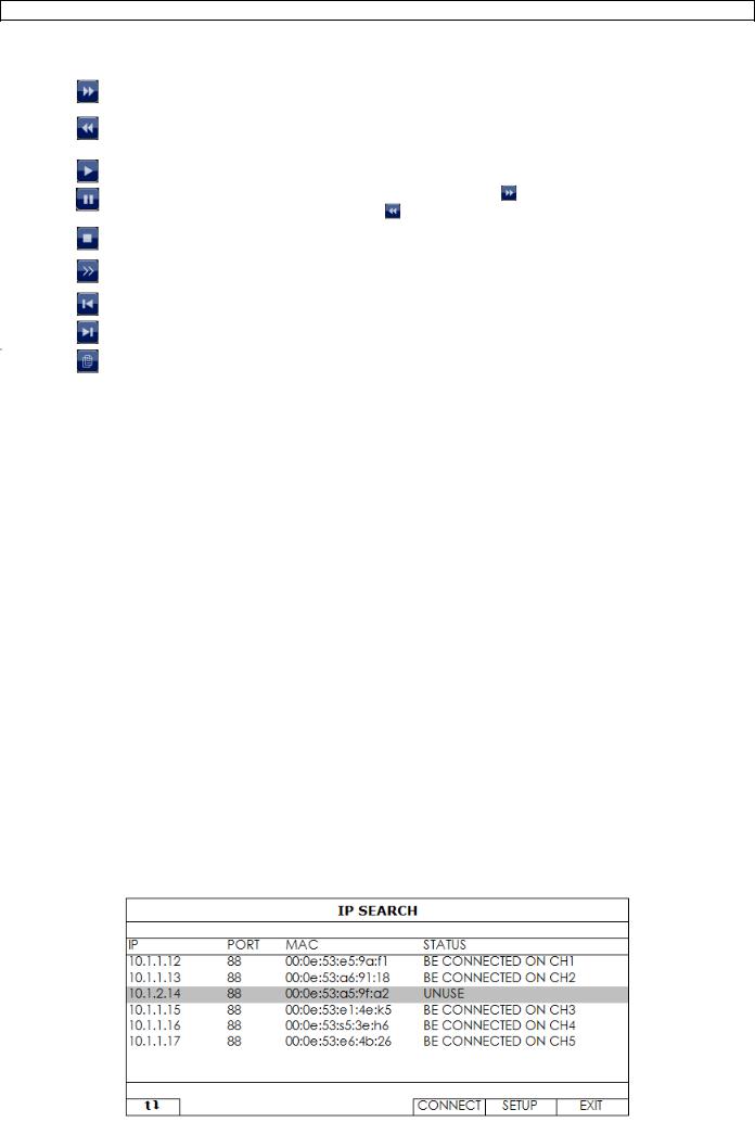
9.2Manual Configuration
If the NVR does not configure the IP address of your camera automatically as described above, the default IP configuration method of your IP camera may not be set to DHCP. To solve this, reconfigure the camera’s IP address to 10.1.1.xx (xx ranges from 11 ~ 253), in the same network segment as the NVR.
1.In the quick operation panel [18], click  . You’ll see the list of every connected IP camera with its connection status and MAC address.
2. Select an IP address that is not used (UNUSED), and click SETUP.
V. 01 – 04/03/2013 |
7 |
©Velleman nv |
NVR2
1.Select STATIC in NETWORK TYPE, and change the IP address to 10.1.1.xx (xx ranges from 11 ~ 253).
2.Click APPLY and EXIT to save your changes.
3.Wait until the NVR detects the IP camera and displays images.
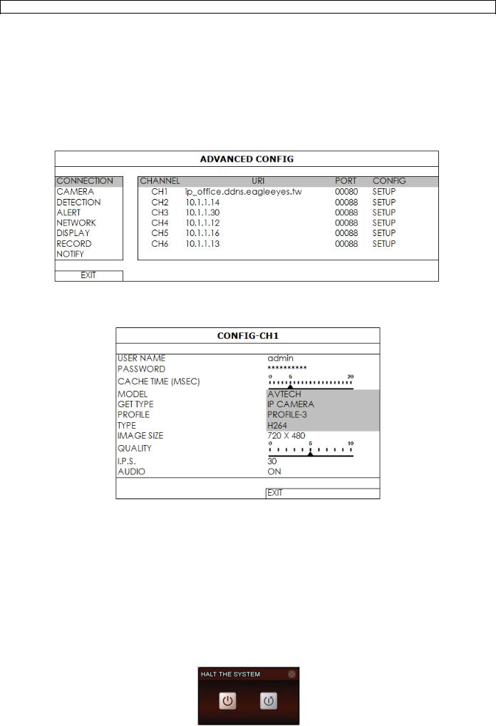
9.3Configuring a remote internet camera
Via internet you can record video images from an IP camera in a remote location.
1.Make sure that the IP camera is accessible outside its LAN network via a dynamic domain name (for example ip_office.ddns.eagleeyes.tw).
2.In the main menu [19], click  (ADVANCED CONFIG) and select CONNECTION.
3.To assign a channel to a remote IP camera, click URI to enter the address of the camera and its port number.
4.Click SETUP to enter the access information of the camera.
5.Enter the user name (USER NAME) and password (PASSWORD) to access the IP camera.
6.Click GET TYPE to detect the camera and make sure the access information is correct.
7.Select the image size (IMAGE SIZE), image quality (QUALITY), and images per second (I.P.S.). Note: The available options depend on the camera you want to connect.
8.Click GET TYPE to detect the camera and make sure the access information is correct.
9.Optional: for a camera with audio recording, set AUDIO to ON or OFF.
10.Quick Operation
10.1 Switching on/off and Rebooting
To power off or reboot the NVR:
In the quick operation panel [18], click  and then click
  (power off) or
  (reboot).
V. 01 – 04/03/2013 |
8 |
©Velleman nv |

NVR2
10.2 Viewing a Channel in Full-Screen Mode
To view a channel in full screen mode, you can:
Click directly on the channel image to see that channel in full screen mode. Double-click the image to restore the previous overview.
In the quick operation panel [18], click  . On the control panel that appears, select the channel you want to display in full screen mode. Click
  to restore the previous overview.
10.3 Playing Recorded Video Clips
1.Make sure that manual and/or event recording is enabled: in the main menu [19], click  (ADVANCED CONFIG) and select RECORD to check or adjust the settings.
2.In the playback panel [20], press the play button  . The recorded files are shown.
3.The fast forward  and fast rewind
  buttons increase/decrease the playback speed. Press the button repeatedly to increase/decrease the speed to 4x, 8x, 16x, or 32x (max.).
4.Press the pause button  to pause playback.
5.Press the stop button  to stop playback and return to live monitoring.
11.Push Video configuration
11.1 Configuring the WAN port
1.Make sure the NVR is properly connected to the router with a RJ45 network cable.
2.From your NVR, select (ADVANCED CONFIG), and select “Network” “WAN”.
V. 01 – 04/03/2013 |
9 |
©Velleman nv |

NVR2
3. Select “DHCP”, and configure the DNS setting and port number.
The default port number is 80. Typically, the TCP port used by HTTP is 80. However in some cases, it is better to change this port number for added flexibility or security.
4.Then, note down the IP address shown in “IP”. This is the IP address assigned to your NVR by the router. You’ll need it later for port forwarding.
5.Go to “DDNS”, and select “eagleeyes” in “SYSTEM NAME”.
6.Note down the whole address under “CURRENT HOST ADDRESS”, such as
MAC000E5318B3F0@ddns.dvrtw.com.tw. This will be the address used to access your NVR remotely.
7.Select “EXIT” to return to the live view, and continue to the next step for port forwarding.
8.From the web browser of your PC, enter the IP address of your router to access your router.
9.Enter the user name and password if needed.
10.In the router setting interface, go to the port forwarding (or virtual server) rule configuration page.
The naming of port forwarding or virtual server may vary based on different router brands. To know where it is, refer to the user manual of your router.
11.Enter the NVR IP address and the port number you just noted down and enable this rule.
11.2 Configuring a push video trigger
Go to Advanced Config > Notify > tab Push Video
You can have the NVR send a push video to your mobile device for every channel. For every channel, you can, depending on the type of alarm sensor:
Send a push video for a normal open contact (NO) Send a push video for a normal closed contact (NC) Select OFF to turn off push video for a channel.
V. 01 – 04/03/2013 |
10 |
©Velleman nv |
NVR2
11.3 Installing the EagleEyes app
Prerequisites
Before installing EagleEyes to your mobile phone for remote surveillance, make sure you have checked the following:
You have subscribed to and you can access mobile internet services for your mobile phone.
Note: You might be charged for internet access via wireless or 3G networks. For the internet access rate details, check with your local network operator or service provider.
You have noted down the IP address, port number, user name and password used to access your network camera from the internet.
Where to download
1.Connect to www.eagleeyescctv.com from your mobile device, and sign in. Please do not try to download EagleEyes from your computer.
o For Android, select the download link from the website to start downloading.
o For iPhone and iPad, two versions of EagleEyes are available: EagleEyesHD Plus (at a fee), and EagleEyesHD Lite (free).
2.Select the version you want, and you will be directed to the App Store to download the application.
3.When the download is completed, EagleEyes will install automatically to the default location or any location you choose.
For more details about configuring and operating EagleEyes, visit the official website www.avtech.com.tw
11.4 Configuration
Before configuring push video, make sure:
4.The DVR system is set up as described in point 3 Connection and Setup in the full manual on the included CD-ROM.
5.The DVR is connected to the internet.
6.The EagleEyes app is installed on your mobile device (see Installing the EagleEyes app above).
7.Open EagleEyes, and add this DVR to the EagleEyes address book.
For more details about EagleEyes operation, visit www.eagleeyescctv.com.
8.In the EagleEyes app, enable push video as described below.
9. Trigger the alarm sensor to see if you successfully receive push video.
12.Technical Specifications
video compression |
H.264 / MPEG4 / MJPEG |
|
|
video input |
1 LAN port up to 12 channels with a hub/switch |
|
|
video output |
HDMI output 1920 x 1080 pixels |
|
|
recording mode |
manual / timer / motion / alarm |
|
|
multiplex operation |
live display, record, playback, backup and network |
|
|
audio I/O |
1 audio output (mono) |
|
|
motion detection area |
22 x 18 grid per camera |
|
|
motion detection sensitivity |
10 adjustable variables with precise calculation for motion detection |
|
|
pre-alarm recording |
yes |
|
|
backup device |
USB 2.0 backup and network remote backup |
|
|
hard disk storage |
built-in SATA type: supports 2 x HDD, supported HDD capacity over 3 TB |
|
(HDD not incl.) |
|
|
|
external eSata: external hard disk or disk array (Linux system support) |
|
|
web interface |
supports free CMS software (Windows & Mac OS) |
|
|
V. 01 – 04/03/2013 |
11 |
©Velleman nv |

|
NVR2 |
|
|
|
|
|
all major internet browsers via Java, QuickTime and VLC plug-in |
|
|
(Internet Explorer, Firefox, Safari, Google Chrome) |
|
|
|
|
mobile surveillance |
software available on www.velleman.be |
|
|
|
|
|
smart phones: push video: on iPad, iPod touch, iPhone, Android phone & |
|
|
tablet |
|
|
remote login via all smart phone platforms (Apple, Android, BlackBerry, Nokia |
|
|
Symbian and Windows Mobile) |
|
|
|
|
|
computer: CMS (Central Management System): remote surveillance to |
|
|
monitor up to 20 different IP addresses (Windows & Mac OS) |
|
|
web browser: Internet Explorer, Firefox, Google Chrome and Safari via Java, |
|
|
Quicktime or VLC plug-in |
|
|
|
|
remote alarm notification |
SMS message, e-mail and image uploading to FTP sites |
|
|
|
|
network connection |
supports TCP/IP, PPPoE, DHCP and DDNS function |
|
|
|
|
power source |
19 VDC / 2.1 A (incl.) |
|
|
|
|
power consumption |
< 40 W |
|
|
|
|
operating temperature |
10 °C ~ 40 °C |
|
|
|
|
system recovery |
system auto recovery after power reconnected |
|
|
|
|
dimensions |
375 x 68 x 264 mm |
|
|
|
|
Use this device with original accessories only. Velleman nv cannot be held responsible in the event of damage or injury resulted from (incorrect) use of this device.
For more info concerning this product and the latest version of this manual, please visit our website www.velleman.eu.
The information in this manual is subject to change without prior notice.
© COPYRIGHT NOTICE
The copyright to this manual is owned by Velleman nv. All worldwide rights reserved.
No part of this manual or may be copied, reproduced, translated or reduced to any electronic medium or otherwise without the prior written consent of the copyright holder.
V. 01 – 04/03/2013 |
12 |
©Velleman nv |

NVR2
KORTE HANDLEIDING
1.Inleiding
Aan alle ingezetenen van de Europese Unie Belangrijke milieu-informatie betreffende dit product
Dit symbool op het toestel of de verpakking geeft aan dat, als het na zijn levenscyclus wordt weggeworpen, dit toestel schade kan toebrengen aan het milieu. Gooi dit toestel (en eventuele batterijen) niet bij het gewone huishoudelijke afval; het moet bij een gespecialiseerd bedrijf terechtkomen voor recyclage. U moet dit toestel naar uw verdeler of naar een lokaal recyclagepunt brengen. Respecteer de plaatselijke milieuwetgeving.
Hebt u vragen, contacteer dan de plaatselijke autoriteiten betreffende de verwijdering.
Dank u voor uw aankoop! Lees deze handleiding grondig voor u het toestel in gebruik neemt. Werd het toestel beschadigd tijdens het transport, installeer het dan niet en raadpleeg uw dealer.
2.Veiligheidsinstructies
Houd dit toestel buiten het bereik van kinderen en onbevoegden.
Elektrocutiegevaar bij het openen van het toestel. Raak geen kabels aan die onder stroom staan om dodelijke elektroshocks te vermijden.
Trek de stekker uit het stopcontact (trek niet aan de kabel!) voordat u het toestel reinigt en als u het niet gebruikt. Houd de voedingskabel altijd vast bij de stekker en niet bij de kabel.
3.Algemene richtlijnen
Raadpleeg de Velleman® serviceen kwaliteitsgarantie achteraan deze handleiding.
Gebruik het toestel enkel binnenshuis. Bescherm het toestel tegen regen, vochtigheid en opspattende vloeistoffen. Plaats geen objecten gevuld met vloeistof op of naast het toestel.
Bescherm dit toestel tegen stof en extreme temperaturen. Zorg dat de verluchtingsopeningen niet verstopt geraken. Voorzie een ruimte van minstens 1" (± 2,5 cm) tussen het toestel en elk ander object.
Bescherm het toestel tegen schokken. Vermijd brute kracht tijdens de bediening van het toestel.
Leer eerst de functies van het toestel kennen voor u het gaat gebruiken.
Om veiligheidsredenen mag u geen wijzigingen aanbrengen aan het toestel. Schade door wijzigingen die de gebruiker heeft aangebracht aan het toestel valt niet onder de garantie.
Gebruik het toestel enkel waarvoor het gemaakt is. Bij onoordeelkundig gebruik vervalt de garantie.
De garantie geldt niet voor schade door het negeren van bepaalde richtlijnen in deze handleiding en uw dealer zal de verantwoordelijkheid afwijzen voor defecten of problemen die hier rechtstreeks verband mee houden.
Bewaar deze handleiding voor verdere raadpleging.
Installeer en gebruik deze camera NIET voor illegale praktijken en respecteer ieders privacy.
4. |
Eigenschappen |
|
opnames in hoge resolutie |
|
|
|
capaciteit: 12 kanaalsmodus: |
720 x 480 pixels: ± 360 IPS |
|
|
1280 x 720 pixels: ± 120 IPS |
|
6 kanaalsmodus: |
720 x 480 pixels: ± 180 IPS |
|
|
1280 x 720 pixels: ± 180 IPS |
|
|
1920 x 1080: ± 90 IPS |
bewaking op afstand via gratis EagleEyes-software op iPhone, iPad en Android
aansluiting met de gsm via GPRS, 3G of Wi-Fi
display met grafische gebruikersinterface (GUI) en USB-muis
V. 01 – 04/03/2013 |
13 |
©Velleman nv |
NVR2
hoge compatibiliteit en off-site back-up: compatibel met de voornaamste IP-camera's die ONVIFgecertificeerd zijn
netwerkopslagfunctie voor back-ups van allerhande IP-camera's op
het internet
werkt met de gratis CMS-software (Central Management System)
voor off-site back-ups
beheer ter plaatse en op afstand, volledig onafhankelijk
HDMI-uitvoerresolutie tot 1080P
optioneel scherm: MONSCA8
adapter: PAC916T
HDMI-kabel: Professional of Premium
optionele harde schijf: HD500GB/S, HD1TB/S, HD2TB/S
USB-muis: meegeleverd
IR-afstandsbediening: meegeleverd
IP-camera's: voor: CAMIP11, CAMIP12
ook compatibel met: CAMIP9, CAMIP13, CAMIP14 & ONVIF-camera's
compatibel met powerline adapter: EM8017, EM8024, EM8025, EM8026
optionele router: EM4542, EM4553, EM4570, PCRT1
5.Omschrijving
Raadpleeg de afbeeldingen op pagina 2 van deze handleiding.
Frontpaneel
1 |
POWER |
Led-indicator: de videorecorder is ingeschakeld |
|
|
|
|
|
|
2 |
ALARM |
LED-indicator: een alarm treedt op |
|
|
|
|
|
|
3 |
WAN |
LED-indicator: de videorecorder is verbonden met het internet |
|
|
|
|
|
|
4 |
LAN |
LED-indicator: de videorecorder is verbonden met het LAN-netwerk |
|
|
|
|
|
|
5 |
SATA |
LED-indicator: SATA harde schijf is actief |
|
|
|
6 |
HDD1/HDD2 |
LED-indicator: er zijn twee harde schijven geïnstalleerd en correct aangesloten |
|
|
|
|
|
Plaats een compatibele USB flash drive voor videoback-up. |
7 |
USB-poort |
Opmerking: Voor een lijst van compatibele USB flash drives, raadpleeg de |
|
|
volledige handleiding op de CD-ROM. |
|
|
|
8 |
muispoort |
Sluit een muis aan (meegeleverd). |
|
|
|
|
|
|
|
|
|
Achterpaneel |
|
|
|
|
|
|
|
|
9 |
RS485 |
RS 485-poort |
|
|
|
10 |
SATA |
Sluit een externe SATA harde schijf aan |
|
|
|
|
|
Sluit aan op een scherm met high-definition video-ondersteuning (HDMI-poort). |
11 |
HDMI-uitvoerpoort |
Opmerking: Gebruik een geschikte adapter (niet meegelev.) voor schermen met |
|
|
VGAof composietvideoconnectoren. |
|
|
|
12 |
LAN |
Verbind met lokale IP-camera’s via een 8P8C (RJ45) netwerkkabel. |
|
|
|
13 |
WAN |
Verbind met internet via een 8P8C (RJ45) netwerkkabel. |
|
|
|
14 |
AUDIO OUT |
Verbind met de Audio Line-ingang van een versterker. |
|
|
|
15 |
DC 19V IN |
Verbind met de voedingsadapter (meegelev.). |
|
|
|
6.De hard disk drive (HDD) installeren
1.Gebruik een compatibele harde schijf (niet meegelev.), type eSATA (Serial Advanced Technology Attachment). Formatteer eerst de harde schijf.
2.Zorg ervoor dat u het toestel ontkoppelt van het lichtnet. Raak geen elektronische circuits aan om elektrostatische ontladingen te voorkomen.
3.Schroef het bovendeksel los en neem het weg.
V. 01 – 04/03/2013 |
14 |
©Velleman nv |

NVR2
4.Plaats de harde schijf in de voorziene montagebeugel.
5.Plaats de harde schijf met de printplaat naar boven en sluit de voedingsen dataconnector aan.
6.Bevestig de harde schijf met de meegeleverde schroeven, twee aan elke kant.
7.Gebruik de extra meegeleverde montagebeugels om een tweede harde schijf te installeren. Bevestig ze aan de onderkant van de videorecorder.
8.Plaats de harde schijf met de printplaat naar boven en sluit de voedingsen dataconnector aan.
9.Plaats de harde schijf in de montagebeugels en bevestig met de meegeleverde schroeven, twee aan elke kant.
10.Plaats het bovendeksel terug en schroef vast.
7.Aansluitdiagram
Opmerking: Om zeker te zijn dat de automatische configuratie goed werkt, sluit eerst de IP-camera’s aan en schakel ze in. Schakel pas dan de videorecorder in.
U kunt tot 12 IP-camera’s aansluiten.
Raadpleeg de afbeeldingen op pagina 2 van deze handleiding.
A |
IP-camera |
E |
scherm met high-definition video- |
|
ondersteuning |
||||
|
|
|
||
|
|
|
|
|
B |
modem |
F |
19VDC-voedingsadapter |
|
|
|
|
|
|
C |
router |
G |
achterpaneel videorecorder |
|
|
|
|
|
|
D |
8P8C (RJ45) netwerkkabel |
H |
hub/switch |
|
|
|
|
|
De IP-camera aansluiten (Plug-and-Play)
1.Verbind de camera met een hub/switch.
2.Wacht tot de camera automatisch geconfigureerd is en de beelden op het scherm verschijnen.
8.Symbolen
Raadpleeg de afbeeldingen op pagina 2 van deze handleiding.
16 |
NVR-status |
|
|
|
|
|
|
|
|
|
|
vergrendeling actief |
|
vergrendeling inactief |
|
|
|
|
|
|
|
kanaalvergrendeling actief |
|
kanaalvergrendeling inactief |
|
|
|
|
|
|
|
USB flash drive / apparaat aangesloten |
|
geen USB-apparaat aangesloten |
|
|
|
|
|
|
|
tijdsgeschakelde opname actief |
|
tijdsgeschakelde opname inactief |
|
|
|
|
|
V. 01 – 04/03/2013 |
15 |
©Velleman nv |

|
|
|
NVR2 |
||
|
|
|
|
|
|
|
|
functie overschrijven actief |
|
|
functie overschrijven inactief |
|
|
|
|
|
|
|
|
sequentiemodus actief |
|
|
sequentiemodus inactief |
|
|
|
|
|
|
|
|
PTZ-modus actief |
|
|
PTZ-modus inactief |
|
|
|
|
|
|
|
|
CPU-belasting |
|
|
|
|
|
|
|
|
|
|
netwerkstatus |
|
|
|
|
|
|
|
|
|
|
(WAN) met internet verbonden |
|
(WAN) niet met internet verbonden |
|
|
|
|
|
|
|
(WAN) lokale verbinding |
|
|
|
|
|
|
|
|
|
(LAN) auto-modus - Mbit/s |
|
(LAN) auto-modus - Gbit/s |
|
|
|
|
|
|
|
(LAN) DHCP / statische IP-modus |
|
(LAN) camera niet aangesloten |
|
|
|
|
|
17 |
beschikbare ruimte op harde schijf |
|
|
|
|
|
|
|
|
18 |
kanaalstatus |
|
|
|
|
|
|
|
|
|
|
automatisch zoeken actief |
|
automatisch zoeken inactief |
|
|
|
|
|
|
|
live-geluid actief |
|
geluid inactief |
|
|
|
|
|
|
|
geluid afspelen actief |
|
geluid afspelen inactief |
|
|
|
|
|
|
|
originele grootte |
|
passend op scherm |
|
|
|
|
|
|
|
opname actief |
|
menselijke aanwezigheid wordt |
|
|
|
gedetecteerd |
|
|
|
|
|
|
|
|
|
|
|
|
|
een alarm doet zich voor |
|
beweging wordt gedetecteerd |
|
|
|
|
|
|
|
live-beelden |
|
afspelen van opgenomen beelden |
|
|
|
|
|
19 |
snelmenu |
|
|
|
|
|
|
|
|
Klik om het uitschakelmenu weer te geven en het apparaat uit te schakelen of opnieuw op te |
|
|
|
starten. |
|
|
|
|
|
|
|
Klik om het kanaalkeuzevenster weer te geven en een kanaal te kiezen. |
|
|
|
|
|
|
|
Selecteer eerst het gewenste kanaal, klik dan op |
om in te zoomen. Klik en sleep het rode |
|
|
kadertje onderaan links in het scherm om het gewenste gebied weer te geven. |
|
|
|
|
|
|
|
Klik om de PTZ-modus te activeren en het PTZ-bedieningspaneel weer te geven. |
|
|
|
|
|
|
|
Klik om het IP-zoekvenster te openen en de verbindingsstatus van elk kanaal te controleren. |
|
|
|
|
|
20 |
hoofdmenu |
|
|
|
|
|
|
|
|
QUICK START |
Klik om de statusweergave, het beeld, de datum en de tijd in te |
|
|
stellen. |
|
|
|
|
|
|
|
|
|
|
|
SYSTEM |
Klik om de systeemconfiguratie in te stellen. |
|
|
|
|
|
|
EVENT |
Klik om het zoekmenu voor events te activeren. |
|
|
INFORMATION |
|
|
|
|
|
|
|
|
|
|
|
|
Klik voor het instellen van verbindingen (CONNECTION), camera |
|
|
ADVANCED CONFIG |
(CAMERA), detectie (DETECTION), meldingen (ALERT), netwerk |
|
|
(NETWORK), weergave (DISPLAY), opname (RECORD) en |
|
|
|
|
|
|
|
|
informatieberichten (NOTIFY). |
|
|
|
|
|
|
SCHEDULE SETTING |
Klik om tijdsgeschakelde opnames in te stellen. |
|
|
|
|
V. 01 – 04/03/2013 |
16 |
©Velleman nv |
NVR2
21 |
Weergavemenu |
|
|
|
|
|
|
|
|
||
|
|
snel vooruit |
Klik om versneld vooruit af te spelen aan 4 tot 32 keer de normale |
||
|
|
snelheid. |
|
|
|
|
|
|
|
|
|
|
|
|
|
||
|
|
snel achteruit |
Klik om versneld achteruit af te spelen aan 4 tot 32 keer de normale |
||
|
|
snelheid. |
|
|
|
|
|
|
|
|
|
|
|
|
|
||
|
|
|
Klik om de laatst opgenomen videoclip af te spelen. Klik opnieuw om |
||
|
|
afspelen/pauze |
te onderbreken. |
|
|
|
|
In pauzemodus, klik één keer op |
om één beeldje vooruit te |
||
|
|
|
|||
|
|
|
springen, of op |
voor één beeldje achteruit. |
|
|
|
|
|
|
|
|
|
stoppen |
Klik om de weergave te stoppen. |
|
|
|
|
|
|
||
|
|
vertraagde weergave |
Klik één keer om de clip af te spelen aan 1/4 van de normale |
||
|
|
snelheid, klik twee keer voor 1/8 van de normale snelheid. |
|||
|
|
|
|||
|
|
|
|
||
|
|
|
Klik om naar het vorige/volgende interval van één uur te springen |
||
|
|
vorige/volgende uur |
(bijvoorbeeld, 11:00 ~ 12:00 of 14:00 ~ 15:00) en de eerste video- |
||
|
|
|
opname in dat tijdsinterval af te spelen. |
||
|
|
|
|
|
|
|
|
snel zoeken |
Klik om het menu te activeren. |
|
|
|
|
|
|
|
|
8.2Toetsvergrendeling
In het statusmenu [15], klik op  (vergrendelen) om de bediening van de videorecorder te vergrendelen,
of klik op  (ontgrendelen) om de bediening weer vrij te geven. Wanneer u de bediening weer vrijgeeft, moet u een gebruikersnaam en wachtwoord ingeven.
Opmerking: De standaard gebruikersnaam en het standaard wachtwoord is “admin”. Verschillende gebruikers hebben verschillende toegangsrechten. Raadpleeg de volledige handleiding (beschikbaar op de CD-ROM) voor meer informatie.
9.Camera op LAN-poort instellen (Plug-and-Play)
Opmerking: Deze configuratie bedoeld voor ETS-camera's.
9.1Automatische configuratie
De videorecorder zal automatisch het IP-adres instellen van een ETS-camera die verbonden is via LAN op voorwaarde dat:
de standaard IP-configuratiemethode van de camera DHCPis.
de camera ingeschakeld is alvorens de videorecorder ingeschakeld wordt.
U kunt altijd het IP-adres van de camera manueel instellen zoals verderop beschreven.
9.2Manuele configuratie
Als de videorecorder het IP-adres van uw camera niet automatisch instelt zoals hierboven beschreven, dan is de standaard IP-configuratiemethode van uw camera niet ingesteld op DHCP. Om dit te verhelpen moet u het IP-adres van de camera opnieuw instellen op 10.1.1.xx (met xx binnen het bereik 11 ~ 253), in hetzelfde netwerksegment als de videorecorder.
1.In het snelmenu [18], kik op  . U ziet een lijst van alle verbonden IP-camera's met hun verbindingsstatus en MAC-adres.
V. 01 – 04/03/2013 |
17 |
©Velleman nv |
Loading...