


PCS32 ASSEMBLY AND CALIBRATION MANUAL
Special tools for testing and adjustment:
∙IBM compatible computer (486 or pentium)
∙Signal generator
∙Digital multimeter
SEE MARKED TEXT FOR MODIFICATIONS
22 / 04 / 1996 |
PCS32i Assembly & Calibration Manual |
2 |
ASSEMBLY
VERY IMPORTANT
-MOUNT ALL COMPONENTS AGAINST THE PCB
-MOUNT THE COMPONENTS IN THE ORDER INDICATED BELOW
The oscilloscope consists of twe PCBs:
1 The small PCB PPCMK2PS, which, among others, supplies the negative voltage; the on/off switch, the fuse and the supply connector are also mounted on this PCB.
2 The base PCB P7103, which the rest of the circuit is mounted on
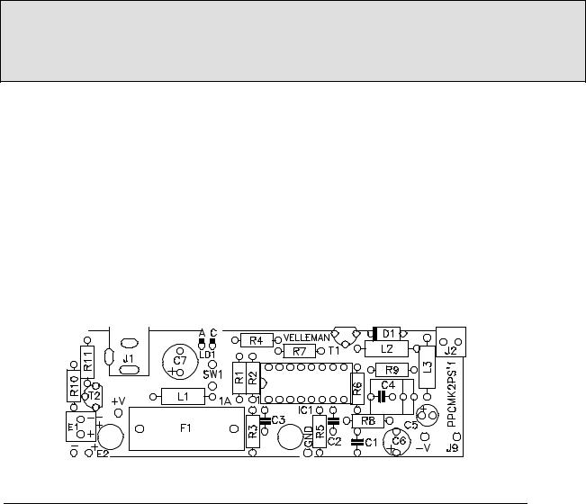
1) ASSEMBLY OF THE POWER SUPPLY PCB PPCMK2PS
Mount the ¼W resistors
R1... R4: 5K6 (green, blue, red, gold) (RA5K6)
R5: 10K (brown, black, orange, gold) (RA10K0)
R6: 47K (yellow, violet, orange, gold) (RA47K0)
R7: 1K (brown, black, red, gold) (RA1K)
R10: 330 ohm (orange, orange, brown) (RA330E0)
22 / 04 / 1996 |
PCS32i Assembly & Calibration Manual |
3 |
Mount the 1% metall film resistors
R8: 20K (red, black, black, red, gold) (MA20K0)
R9: 1R5 (brown, green, black, silver; brown) (MA1E5)
R11: 30 ohm (orange, black, black, gold, brown) (MA30E0)
Mount the coils
L1... L3: 220µH (red, red, brown) (220H0)
Mount the diodes (watch the polarity!)
D1: 1N4148 (1N4148)
Mount the ic sockets
IC1: 16P (16P)
Mount the capacitors
C1, C2: 2n2 (222) (C2N2)
C3: 100nF (104, µ1) (C100N0)
C4: 1µF (105) (C1M0)
Mount the electrolytic capacitors (watch the polarity!)
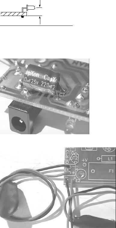
C5: 4,7µF (4µ7) (4J7J) Completely against PCB !
C6: 100µF (100J0D) Completele against PCB !
Mount the transistor
T1: BC327 (BC327)
T2: BC547 (BC547B)
Mount the fuse holder (FUSE/H’LC)
F1: Insert a 1A fuse in the fuse holder (FU1)
Mount the DC connector
J1: type (DJ-005)
Mount the screw connector |
(SCREW02) |
J2 |
|
REMARK: FASTEN THE TWO SCREWS !!!!!!!!!!!!!!!!!!!
Mount the 3mm LED (LED3RL)
LD1
22 / 04 / 1996 |
PCS32i Assembly & Calibration Manual |
4 |
4mm
Insert the IC
Watch the position of the notch!IC1: CA3524 (CA3524)
MOUNT C7: 220µF (220J0D) AT SOLDER SIDE !
Connect snap 9V (2x) (red= +) (SNAP9V)
22 / 04 / 1996 |
PCS32i Assembly & Calibration Manual |
5 |

2) ASSEMBLY OF THE MAIN PCB P7103’3
22 / 04 / 1996 |
PCS32i Assembly & Calibration Manual |
6 |
Mount the ¼W resistors
R1, R2, R42... R45,
R49, R51... R58: 470R (yellow, violet, brown, gold) (RA470E0)
R48, R50, R59... R61: 100R (brown, black, brown, gold) (RA100E0)
R29, R30: 100K (brown, black, yellow, gold) (RA100K0)
R3, R41: 47R (yellow, violet, black, gold) (RA47E0)
R46: 1K (brown, black, red, gold) (RA1K0)
R67, R68: 4K7 (yellow, violet, red, gold) (RA4K7)
22 / 04 / 1996 |
PCS32i Assembly & Calibration Manual |
7 |
Mount the 1% metall film resistors
R9, R24: 360R (orange, blue, black, black, brown) (MA360E0)
R4, R14: 820R (grey, red, black, black, brown) (MA820E0)
R15, R34... R39: 1R5 (brown, green, black, silver; brown) (MA1E5)
R5, R16: 750ohm (purple, green, brown, gold) (MA750E0)
R10, R20: 30R (orange, black, black, gold, brown) (MA30E0)
R11, R21: 82R (grey, red, black, gold, brown) (MA82E0)
R47: 110R (brown, brown, black, black, brown) (MA110E0)
R7, R18, R31, R32: 200R (red, black, black, black, brown) (MA200E0)
R8, R19, R25.. R28: 470R (yellow, violet, black, black, brown) (MA470E0)
R13, R23: 10K (brown, black, black, red, brown) (MA10K0)
R12, R22: 91K (white, brown, black, red, brown) (MA91K0)
R6, R17: 910K (white, brown, black, orange, brown) (MA910K0)
R33, R40: 3R3 (orange, orange, black, silver; brown) (MA3E3)
Mount the diodes (watch the polarity!)
D1... D9, D11, D23... D26: 1N4148 (1N4148)
D13, D21: 1N4000... 4007 (1N4007)
Mount the adjustable resistors
RV1, RV4: 100ohm multiturn (E100TW or E100TY)
RV3, RV6: 4K7 (5K) (K004SH)
Mount the IC sockets
IC15, IC22: 24P
Mount the capacitors
22 / 04 / 1996 |
PCS32i Assembly & Calibration Manual |
8 |
C89, C90: 10P |
(C10) |
|
|
C86, C87: 100P (101) |
(C100) |
|
|
C3, C8: 100P (101) |
(C100) |
|
|
C14, C20: 150P (151) |
(C150) |
|
|
C17, C26: 1N5/400V! (152, 1500) (5MQ1.5) |
|
||
C15, C21: 2N2 (222) |
(C2N2) |
|
|
C4, C5, C9... C12, C41... C63, |
|
||
C28, C29, C32, C37: 47nF (473) (C47N0) |
|
||
C23, C38... C40, |
|
|
|
C64... C70: 220nF (224) (C220N0M) |
|
||
C25, C31: 47N/400V (K400) (1MK47) |
|
||
C35, C36, C75, C76, C91, C92: 100N (104) |
(C100N0) |
||
C18 & C27 : 10nF (C103) |
|
||
DO NOT MOUNT: C13, C19, C16 |
|
||
Mount the adjustable capacitors
CV1, CV3: 22P (green) (TRIM22P)
CV2, CV4: 50P (yellow) (TRIM65P)
Mount the transistors
T3, T5: 2N2907A (2N2907A)
T1, T2,: U441 (U441)
22 / 04 / 1996 |
PCS32i Assembly & Calibration Manual |
9 |
 Loading...