How it Works
Log In / Sign Up
Buy Points
How it Works
FAQ
Contact Us
Questions and Suggestions
Users
Velleman
Loading...
D
DVM9912
DVM9915
2
DVMEMF
DVR16H1
2
DVR16H2
DVR16H3
DVR16T2
DVR4H2
DVR4H3
DVR4H4
DVR4L6
DVR4LCD
2
DVR4MQAE
DVR4MQAEB
DVR4MQAEE
DVR4T1
DVR4T3
DVR4USB
DVR4USBH
DVR8H1
DVR8H2
DVR8H3
DVRSD1
DWH-A059I
E
E300GSM
E305D2
E305DIN1
E305DO
E305EM5
E305EM5-G
E305W
E305WO
EARC15
EC16B
ECM1
ECM330
ED31168
ED91010
ED91011
ED91014
ED91015
ED91016
ED91120
EDA5001
EDB4
EDB5
EDU01
2
EDU02
EDU03
EDU05
2
EDU06
2
EDU08
4
EDU09
4
EDU10
EFANF60
EFL44
2
EHD2
EHF1
EHI2KW
EMDIN01
2
EMDIN02
EMDIN03
EP-101
EP-107
EPATH3
ESR70
ET20
EVM125
EVM1400
EVM439
EVM831
EVM851
EVM892
EVT04
F
FM10BT
FM3
FM6
FM8
FM9
G
GASIRON2
GASMT1
GAS/SET2
GCOMP435
GIK06
GIK07
GIK10
GIK11
GIK12
GIK13
GIK15
GMK1LAMP
GMK2LAMP
GPARB1
GPS16
GRR01
GRR02
GSCRU2
GWP1
GWP2
GWP3
Loading...
Loading...
Nothing found
EDU06
Assembly instructions
24 pgs
2.35 Mb
0
Datasheet
1 pgs
1.58 Mb
0
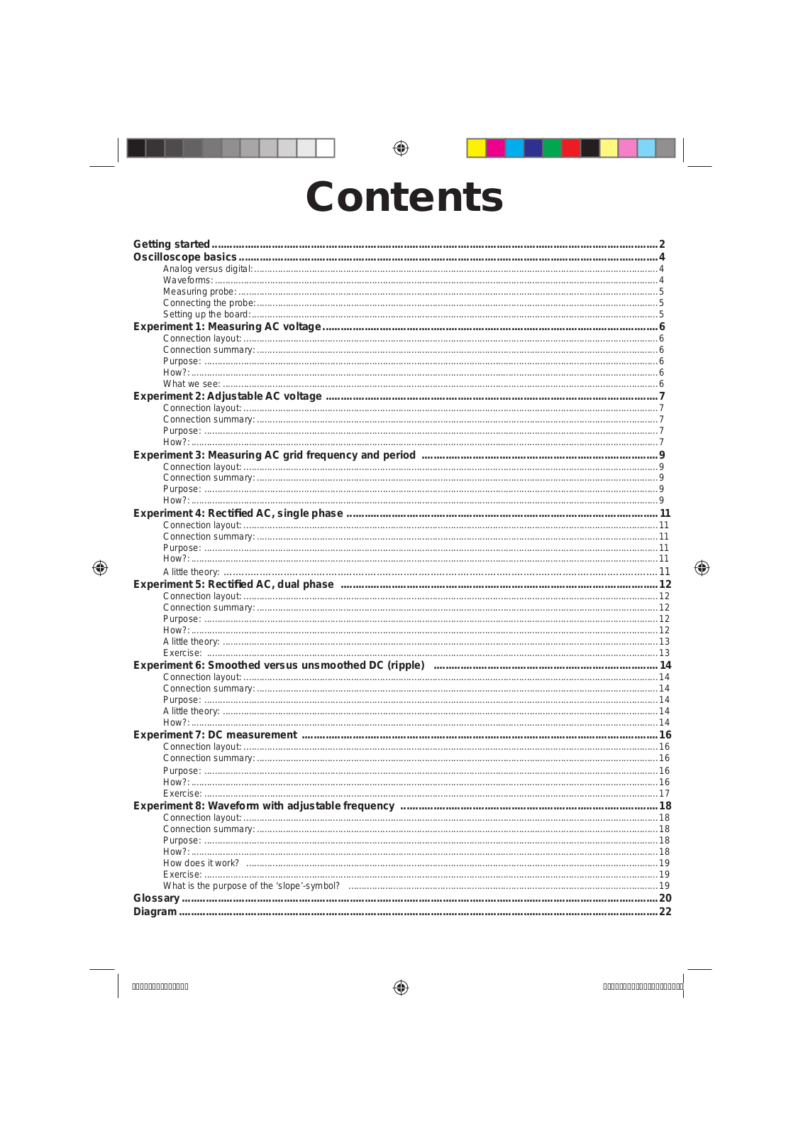
Table of contents
Loading...
Velleman EDU06 Assembly instructions
...
Velleman Assembly instructions
Download
Specifications and Main Features
Frequently Asked Questions
User Manual
Download
Loading...
+
hidden pages
Unhide
You need points to download manuals.
1 point = 1 manual.
You can buy points or you can get point for every manual you upload.
Buy points
Upload your manuals