


HAA85BL
SELF-CONTAINED DIGITAL ACCESS CONTROL KEYPAD WITH BACKLIGHT ONAFHANKELIJK DIGITAAL TOETSENBORD MET ACHTERGRONDVERLICHTING DIGICODE NUMÉRIQUE AUTONOME AVEC RÉTRO-ÉCLAIRAGE EIGENSTÄNDIGES DIGITALES CODESCHLOSS MIT HINTERGRUNDBELEUCHTUNG TECLADO DIGITAL AUTÓNOMO CON RETROILUMINACIÓN
USER MANUAL |
2 |
GEBRUIKERSHANDLEIDING |
19 |
MODE D’EMPLOI |
35 |
MANUAL DEL USUARIO |
51 |
BEDIENUNGSANLEITUNG |
67 |
HAA85BL
USER MANUAL
1. Introduction & Features
To all residents of the European Union
Important environmental information about this product
This symbol on the device or the package indicates that disposal of the device after its lifecycle could harm the environment.
Do not dispose of the unit (or batteries) as unsorted municipal waste; it should be taken to a specialized company for recycling.
This device should be returned to your distributor or to a local recycling service. Respect the local environmental rules.
If in doubt, contact your local waste disposal authorities.
Thank you for buying the HAA85BL! Please read the manual thoroughly before bringing this device into service. If the device was damaged in transit, don't install or use it and contact your dealer.
The HAA85BL is a self-contained security keypad (with backlight) and is a reliable and cost-effective solution for residential and commercial installations. It is compatible with virtually any electric locking device and can be used as a control for security systems, automatic operators and machinery. Over 100 million combinations are possible for the user codes (multi-user mode). Programmed data stored in the system is non-volatile. For indoor use only. Backlit keyboard: dim in stand-by, brightens for 10 seconds at the press of a key.
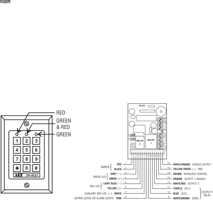
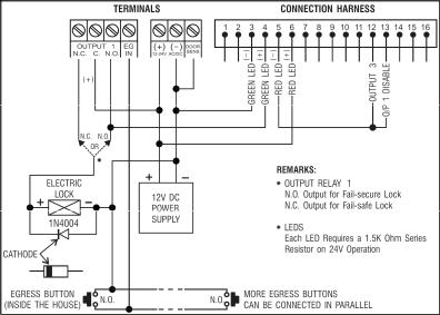
2. Connections (fig. 1)
THE LED INDICATORS
∙RED & GREEN
The red and green LEDs are to be connected at the installer’s will.
∙AUX RED / GREEN
The green LED is a status indicator at normal operation. The LED changes to steady red while the auxiliary red LED is energized.
THE TERMINAL BLOCK
v2 15/11/2013 |
2 |
VELLEMAN |
HAA85BL
∙OUTPUT 1
5A dry relay contacts, recommended for door strike controls. Normally Open (N.O.) and Normally Closed (N.C.) outputs are available. Use N.O. output for fail-secure locking device and N.C. output for fail-safe locking device. The relay can be programmed in start/stop (toggle) mode or timer mode from 1 to 999 seconds.
∙EG IN (EGRESS INPUT)
A N.O. input terminal refers to (-) ground with the help of a N.O. button to deactivate the output 1. The egress button is usually put inside the house near the door. More than one egress button can be connected in parallel to the terminal. Leave this terminal open if it is not used.
∙12V-24V AC/DC (POWER INPUT)
Connect to 12V-24V AC/DC power supply. The (-) supply and GND (wire 15) are the common grounding points of the keypad system. No selection jumper is required for the full input voltage range. Connect DC power with the (+) and (-) polarity; there is no discrimination for the AC power input.
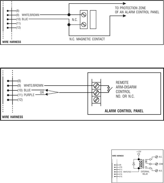
∙DOOR SENS (DOOR POSITION SENSOR INPUT)
A N.C. input terminal referring to (-) ground. With the help of a N.C. magnetic door switch, the system will monitor the position of the door and will give the following functions:
1.Door Auto Relock
The system will immediately relock the door after valid access has been gained before the end of the programmed time for output 1.
2.Door Forced Open Alarm
The keypad will generate door forced-open alarm instantly if the door is forced open without a valid user entry or egress input. The alarm will last for 60 seconds and can be stopped with user code 1 or one of the user codes in group 1. This function is selectable via the programming options at location 801.
3.Door Propped-Up Alarm
When the door is left open longer than the allowable time. The keypad will generate door propped-up alarm after the expiry of the preset door opening time until the door is closed again. The door opening time is programmable from 1 to 999 seconds at location 9.
4.Interlock Control
The interlock control output goes to (-) while the door is open in order to give signal to disable the other keypad in the interlock system.
THE WIRE HARNESS
NOTE: Always hold the PCB tightly and gently pull out the socket to prevent damage of the electronic assembly of the keypad.
∙N.C. TAMPER (1-2)
N.C. contact when the keypad is secured on the box. It is open when the keypad is separated from the box. Connect the terminal to the 24-hour zone of an alarm system if necessary.
∙GREEN, RED & AUXILIARY RED LEDs (3-4), (5-6) & (7)
Three on-board LED lamps are available. They are prepared for free connections. Connect these to the remote indicator driving terminals of your equipment such as an alarm control panel. Mind the polarity.
The green and red lamps that are independent are equipped with 1.5k Ω current limiting resistor.
v2 15/11/2013 |
3 |
VELLEMAN |
HAA85BL
The anode of the auxiliary red LED is connected to the +5V internally. It turns on with the cathode (wire 7) connected to (-) ground.
∙KEYPAD ACTIVE OUTPUT OR ALARM OUTPUT (8)
An NPN transistor open collector output with max. rating of 100mA sink and 24VDC. It is selectable to give Keypad Active Output or Alarm Output via the K or A jumper.
1.Keypad Active Output (KEY)
It switches to (-) ground for 10 seconds with each press of the key. This can be used to turn on lights, CCTV cameras or buzzer.
2.Alarm Output (AL)
Switches to (-) ground when the Door Forced Open Alarm or Door Propped-Up Alarm occurs in order to trigger the external alarm to give notification at a remote location.
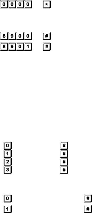
∙OUTPUT 2 (9-10-11)
Auxiliary relay output with 1A N.O. and N.C. dry contacts controlled by user code 2 and ideal for controlling security systems and automatic operators. It is programmable for start/stop (toggle) operation or timing operation from 1 to 999 seconds.
∙OUTPUT 3 (12)
An NPN transistor open collector output ideal for auxiliary control functions such as security systems. This output is programmed for start/stop (toggle) operation or timing operation from 1 to 999 seconds. It switches to (-) ground when active and the max. rating is 100mA sink / 24VDC.
∙OUTPUT 1 DISABLE (13)
A N.O. input terminal refers to (-) ground. Neither user code 1 nor egress button can activate output 1 when this terminal is tied to (-) ground. It is prepared for cross-wired connection in an interlock application.
∙INTERLOCK CONTROL OUTPUT (14)
An NPN transistor open collector output. It is off at normal condition and switches to (-) ground immediately for the first 5 seconds after keying in a valid user code to operate output 1. Then, it will keep tying to (-) during the time that the door position sensor is open. Use this output to control the other keypad in an interlock system to prevent both doors from opening at the same time.
∙DURESS OUTPUT (16)
An NPN open collector output. It switches to (-) ground when the duress code is entered. Use it to trigger an alarm zone or to turn on a buzzer to notify a guard. Ic max.: 100mA sink; Vc max.: 24VDC.
3. The Pacifier Tones & LED Indicating Signals
The built-in buzzer and the green LED indicator in the centre give the following tones and signals for operation status:
|
STATUS |
TONES* |
LED SIGNALS |
1. |
In programmable mode |
- - - |
ON |
2. |
Successful key entry |
1 beep |
1 flash |
3. |
Successful code entry |
2 beeps |
2 flashes |
4. |
Unsuccessful code entry |
5 beeps |
5 flashes |
5. |
DAP jumper not replaced |
Continuous beeps |
Continuous flashes |
6. |
In standby mode |
- - - |
1 flash in 2-seconds interval |
7. |
Output relay activated |
1-second long beep** |
- - - |
NOTE: * All pacifier tones can be enabled or disabled through programming options at location 83.
v2 15/11/2013 |
4 |
VELLEMAN |
HAA85BL
**The output activation beep can be enabled or disabled through programming options at location 82.
4.Reset master code
If you have forgotten the master code, you can reset it. For the master code, do not use a combination that is already taken for a user code.
1.Disconnect power supply.
2.Displace the DAP jumper from OFF to ON.
3.Reconnect power supply (buzzer is activated).
4.Put the DAP jumper back to OFF position (this done, the buzzer is de-activated).
5.The Keypad is in programming mode and ready to receive your new programming data.
6.Enter a new 4-digit master code at location 0 in case you have forgotten the old master code.
7.Enter the new programming data starting from Section B) in the summary chart shown below.
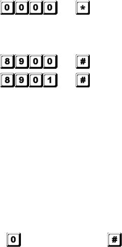
5. The Factory-Set Master Code – Important Note
When programming for the first time, the master code 0000 shall be used. In all cases, program a new master code to invalidate the old master code and to ensure security.
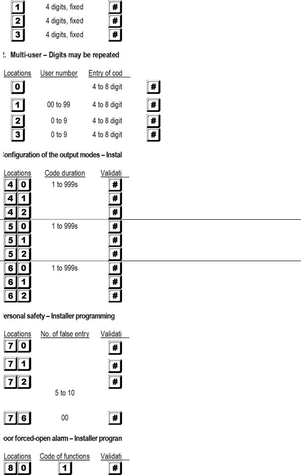
6. Programming the Keypad – Summary Chart
A) Use the factory-set master code entry in programming -- When starting for first time only
Entry of code |
Validation Comments |
Enter in programming mode by factory set master code
B) Set the system to single or multi-user mode and refresh the system – Installer programming
Entry of code |
Validation Comments |
|
Set the system to single user mode, clear all previously stored |
|
data and refresh system |
|
Set the system to multi-user mode, clear all previously stored |
|
data and refresh system |
C) Record the personal master code and user codes – User programming
Notes: master code
∙When programming the codes, it is recommended to program the master code before the user codes.
∙If you are programming a new master code, do not use a combination that is already taken for a user code.
∙If you have forgotten the master code, you can reset it. See section 4 Reset master code.
Notes: user code
∙Any user code must be different from the master code.
∙It is recommended to program a different code for every user.
1.Single user – Digits may be repeated
Locations |
Entry of codes |
Validation Comments |
|
4 digits, fixed |
Personal master code and super user code |
v2 15/11/2013 |
5 |
VELLEMAN |
HAA85BL
User code 1 for output 1 with duress code function
User code 2 for output 2
User code 3 for output 3
2
Validation Comments
Personal master code and super user code
100 user codes in group 1 for output 1 with duress code function
10 user codes in group 2 for output 2
10 user codes in group 3 for output 3
D) |
programming |
Comments
Output 1 momentary mode from 1 to 999 seconds
Output 1 in start/stop mode (toggle)
Output 1 in start/stop mode w/ accelerated code
Output 2 momentary mode from 1 to 999 seconds
Output 2 in start/stop mode (toggle)
Output 2 in start/stop mode w/ accelerated code
Output 3 momentary mode from 1 to 999 seconds
Output 3 in start/stop mode (toggle)
Output 3 in start/stop mode w/ accelerated code
E)
Comments
After 10 successive false codes, the keypad locks during 30 seconds
After 10 successive false codes, the duress output switches to ground
Selectable after 5 to 10 successive false codes, the keypad locks during 15 minutes. The keypad can be reset to release locking with the master code at any time during the locking period.
All of the above securities disappear
F)
Comments
Door forced-open alarm is enabled
v2 15/11/2013 |
6 |
VELLEMAN |
HAA85BL
Door forced-open alarm is disabled
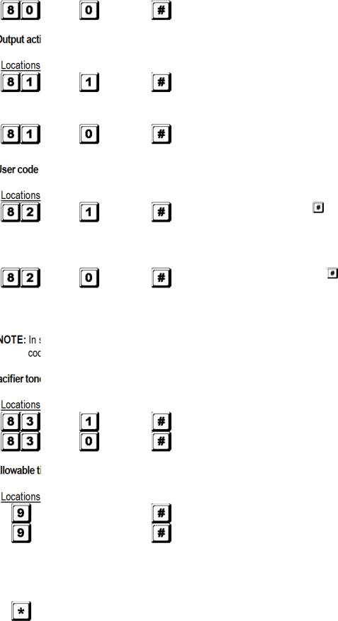
G)activation announcer – Installer programming
|
|
Code of functions |
Validation |
Comments |
|
|
|
|
|
1-second notifying beep is given to notify the person |
|
|
|
|
|
outside to open the door when the output relay is |
|
|
|
|
|
activated with a user code or egress button. Good for a |
|
|
|
|
|
locking device without sound such as a magnetic lock. |
|
|
|
|
|
Notifying beep disabled and replaced by 2 short |
|
|
|
|
|
successful code entry beeps for valid user codes |
|
H) |
entry mode (auto or manual) – Installer programming |
|
|||
|
|
Code of functions |
Validation |
Comments |
|
|
|
|
|
Auto entry code is selected. |
key following the user |
|
|
|
|
code is NOT required in code entry. The user code |
|
|
|
|
|
MUST be set in the same digit length as the master |
|
|
|
|
|
code in auto entry mode and the code length can be 4 |
|
|
|
|
|
to 8 digits long. |
|
|
|
|
|
Manual entry mode is selected. |
key following the |
|
|
|
|
user code is required in code entry. The user codes |
|
|
|
|
|
can be 4 to 8 digits long and they are not required to |
|
|
|
|
|
be the same length as the master code. |
|
single user mode, no matter the selection (auto or manual mode), the master code and the user MUST be set as a 4-digit number.
I) |
|
(keypad acknowledgement tones) – Installer programming |
|
|
|
Code of functions |
Validation Comments |
|
|
|
Pacifier tones available on the keypad |
|
|
|
All pacifier tones are off. |
J) |
time to start door propped-up alarm – Installer programming |
||
|
|
Code of functions |
Validation Comments |
|
0 |
No propped-up alarm |
|
|
|
1 to 999 |
Allowable time from 1 to 999 seconds before door |
|
|
propped-up alarm starts |
|
|
|
|
|
K) Exit programming mode
Validation Comments
Exit programming mode and return to normal operation
7. Single User or Multi-User Mode Selection
The HAA85BL has been factory-set in single user mode with  as master code.
v2 15/11/2013 |
7 |
VELLEMAN |
HAA85BL
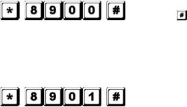
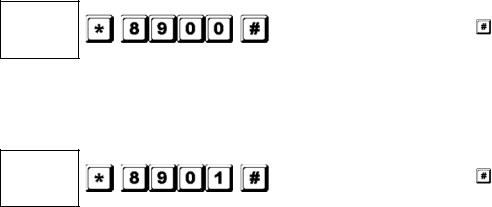
Single user mode (command code: 8900)
Each output can only be operated by one user code. The user code must be 4 digits long. There are 10 000 possible code combinations. The code can be programmed directly into the user code locations 1, 2 and 3 respectively for the 3 outputs. Refer to “6. C) 1. Single user – Digits may be repeated” for more details. This mode is always set with auto code entry in default. You do not need to press  in user code entry. Only enter the 4-digit user code.
NOTE: The system can be set for manual code entry with programming option 0 at location 82 if necessary.
Multi-user mode (command code: 8901)
Up to 100 individual codes will operate output 1 and 10 individual codes will operate output 2 and 3. The user code can be 4 to 8 digits long. There are over 100 million possible code combinations. The user codes can be set for auto or manual entry with programming options at location 82. Default mode is manual entry mode. Pressing
 after code entry is required. Once the keypad is programmed in auto entry, the master code and the user codes MUST consist of the same number of digits. Do not press
  after entering the user code.
Default values
Default |
Comments |
Default |
Comments |
401 |
Output 1 in 1-second momentary |
811 |
Output relay activation beep on |
|
mode |
|
|
501 |
Output 2 in 1-second momentary |
820 |
User code manual entry mode* (multi- |
|
mode |
|
user) |
601 |
Output 3 in 1-second momentary |
821 |
User code auto entry mode* (single |
|
mode |
|
user) |
70 |
After 10 successive false codes, the |
831 |
Pacifier tones on |
|
keypad locks during 30 seconds |
|
|
800 |
Door forced-open alarm disabled |
90 |
No propped-up alarm |
NOTE: * All default values in multi-user and single user mode are exactly the same except the user code entry mode.
Code entry limitation in multi-user mode due to duress code
The system comes with duress function for user code 1 in single user mode and all the user codes of group 1 in multi-user mode. The duress code is automatically set by the system by taking the first digit of the user code and adding or subtracting 2. To prevent other codes falling in the duress code, the first digit of a stored user code +2 or -2 is not allowed as a later user code entry.
Example: User code 56789 was stored in the system. User codes 36789 and 76789 are not allowed.
Set the system to single user mode
Set the system to single user mode with the command code 8900. The system will stay in that mode until it is refreshed. Make sure the master code is 4 digits long.
MASTER |
Single user mode enabled. Wait 2-3 seconds after |
CODE |
pressing until you hear confirmation beeps. |
Set the system to multi-user mode
Set the system to multi-user mode with the command code 8901. The system will stay in that mode until it is refreshed.
MASTER |
Multi-user mode enabled. Wait 2-3 seconds after |
|
|
v2 15/11/2013 |
8 |
VELLEMAN |
|
HAA85BL |
|
|
|
|
CODE |
pressing |
until you hear confirmation beeps. |
Refreshing the system
When choosing a different operation mode (see above), the system will reset and clear all values except for the master code.
NOTE: Make sure the user code and the master code are both 4 digits long when operating in single user mode.
8.Programming and Use of the Keypad – Operation Examples
A)Programming procedures
a.Your HAA85BL is programmed from the keypad. All programmed information is stored in the non-volatile memory.
b.Set the keypad into programming mode first with the master code and press  to validate.
NOTE: Use the DAP jumper to set the keypad into programming mode in case you forgot the master code.
See section 4 Reset master code.
c.Go to a location and program the options. See “6. Programming the Keypad – Summary Chart”.
d.Program the options until all options are programmed. Repeat the programming of an option in case of a wrong entry.
LOCATION 1
…
LOCATION n
OPTION
OPTION n
e.Exit the programming mode with  . All input information has been saved.
B)Single user mode operation – Example
1.Requirements
a.Single user mode
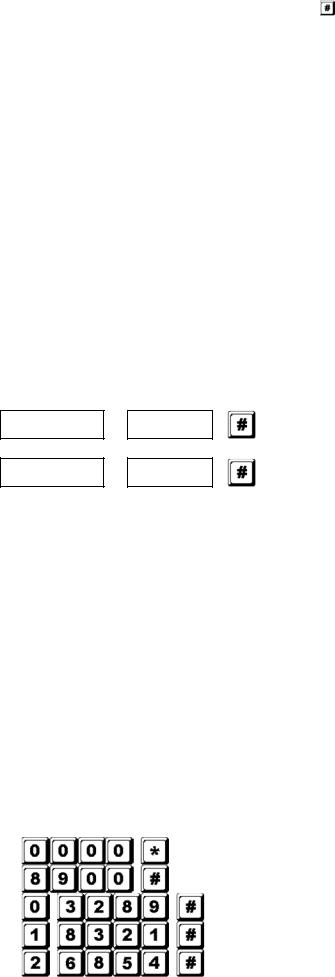
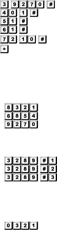
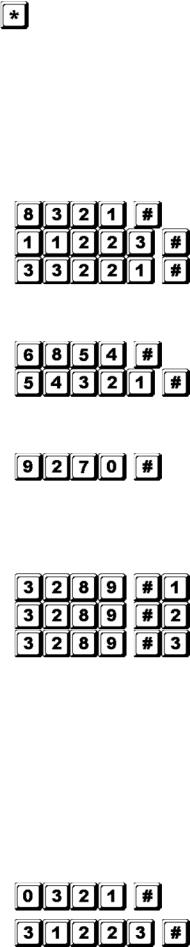
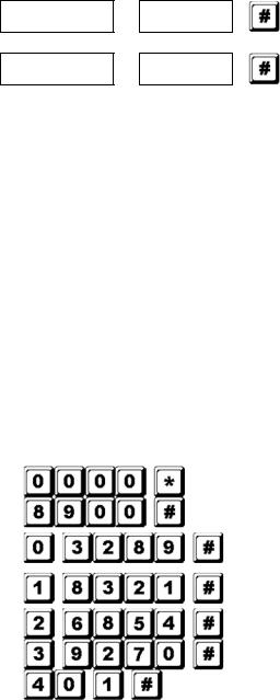
b.Change the factory-set master code 0000 to a personal master code 3289
c.Set user code 1 to 8321
d.Set user code 2 to 6854
e.Set user code 3 to 9270
f.Set output 1 to momentary mode, 1 second
g.Set output 2 to start / stop mode
h.Set output 3 to start / stop mode
i.Set the keypad to lock itself during 15 minutes after 10 successive false codes
2.Programming – Setting the above requirements into the keypad
Program mode with factory-set master code
Single user mode*
3289 stored as new personal master code and super user code
8321 stored as user code1 with duress code function for output 1
6854 stored as user code 2 for output 2
v2 15/11/2013 |
9 |
VELLEMAN |
HAA85BL
9270 stored as user code 3 for output 3
Output 1 set as momentary mode, 1 second
Output 2 set to start / stop mode
Output 3 set to start / stop mode
Keypad set to lock during 15 minutes after 10 successive false codes
Exit programming mode. All above data stored and ready for use
NOTE: * Entering single user command code 8900 is not necessary if the keypad was already in single user mode.
Cancel a wrong entry with  or wait 10 seconds and retry.
3.Operating the keypad – Taking the data programmed above and other default features as reference a. To command an output, only enter the user code. Pressing  is not required.
Output 1 activates for 1 second
Output 2 starts or stops
Output 3 starts or stops
b.The personal master code is a super user code to command the outputs. This feature allows you to use
only one code to operate several keypads with the same master code but different user codes. Enter the personal master code and validate with  and the corresponding output number.
Output 1 activates for 1 second
Output 2 starts or stops
Output 3 starts or stops
c.The duress code does not need to be programmed. The keypad automatically determines the duress code by increasing the first digit of user code 1 with two units.
Example: If user code 1 is 1234, then the duress code will be 3234. If user code 1 is 8321, then the duress code will be 0321.
To command the duress function, enter the duress code.
Duress output activates (output switches to (-) ground) and output 1 activates for 1 second
NOTE: The duress code has 2 functions: it activates the duress output and at the same time it activates output 1 as user code 1. The duress code can always activate or deactivate (in start / stop mode) output 1, but cannot deactivate (reset) the duress output.
d.The accelerated code is the first two digits of the user code. If output 1 has been programmed in start / stop mode with accelerated code at location 42, it will be possible to activate output 1 with only the first two digits of the user code. Deactivation always requires the composition of the complete user code.
Example: Output 1 has been reprogrammed to start / stop mode with accelerated code (location 42). Complete code: 8321, accelerated code: 83.
v2 15/11/2013 |
10 |
VELLEMAN |

|
HAA85BL |
|
starts |
|
stops |
e. |
the safety. The HAA85BL will consider 4 digits as one |
|
code entry. The keypad will lock itself during 15 |
|
keypad can be reset during the locking period by entering |
|
reset and keypad resumes normal operation |
C)Multi- 1.
a. |
|
b. |
personal master code 3289 |
c. |
|
d. |
|
e. |
|
f. |
|
g. |
|
h. |
|
i. |
|
j. |
|
k. |
|
l. |
after 10 successive false codes |
2. |
into the keypad |
|
Program mode with factory-set master code |
|
Multi-user mode* |
|
3289 stored as new personal master code and |
|
super user code |
|
8321 stored as 1st user code in group 1 with |
|
duress code function |
|
11223 stored as the 2nd user code in group 1 with |
|
duress code function |
|
33221 stored as the 3rd user code in group 1 with |
|
duress code function |
|
6854 stored as the 1st user code in group 2 |
|
54321 stored as the 2nd user code in group 2 |
|
9270 stored as the 1st user code in group 3 |
|
Output 1 set to momentary mode, 1 second |
|
Output 2 set to start / stop mode |
|
Output 3 set to start / stop mode |
|
Keypad set to lock during 15 minutes after 10 |
|
successive false codes |
v2 15/11/2013 |
11 |
VELLEMAN |
HAA85BL
Exit programming mode. All above data stored and ready for use
NOTE: * Entering single user command code 8901 is not necessary if the keypad was already in single user mode.
Cancel a wrong entry with  or wait 10 seconds and retry.
3.Operating the keypad – Taking the data programmed above and other default features as reference a. To command output 1, enter one of the user codes in group 1 and validate with  .
.
Output 1 activates for 1 second
Output 1 activates for 1 second
Output 1 activates for 1 second
b. To command output 2, enter one of the user codes in group 2 and validate with  .
.
Output 2 starts or stops
Output 2 starts or stops
c. To command output 3, enter one of the user codes in group 3 and validate with  .
.
Output 3 starts or stops
d.The personal master code is a super user code to command the outputs. This feature allows you to use
only one code to operate several keypads with the same master code but different user codes. Enter the personal master code and validate with  and the corresponding output number.
Output 1 activates for 1 second
Output 2 starts or stops
Output 3 starts or stops
e.The duress code does not need to be programmed. The keypad automatically determines the duress code by increasing the first digit of user codes in group 1 with two units. All user codes have duress code function.
Example: |
User codes in group 1 |
Corresponding duress codes |
|
8321 |
0321 |
|
11223 |
31223 |
|
33221 |
53221 |
To command the duress function, enter the duress code(s).
Duress output activates (output switches to ground) and output 1 activates for 1 second
Duress output activates (output switches to ground) and output 1 activates for 1 second
v2 15/11/2013 |
12 |
VELLEMAN |

HAA85BL
Duress output activates (output switches to ground) and output 1 activates for 1 second
NOTE: The duress code has 2 functions: it activates the duress output and at the same time it activates output 1 as user code in group 1. The duress code can always activate or deactivate (in start / stop mode) output 1, but cannot deactivate (reset) the duress output. Only the user codes in group 1 can deactivate (reset) the duress output.
f.The accelerated code is the first two digits of the user code(s). If the output has been programmed in start / stop mode with accelerated code (programming option 42 for user codes in group 1 and programming option 52 for user codes in group 2), it will be possible to activate the output with only the first two digits of the user code(s). Deactivation always requires the composition of the complete user code(s) in their code group.
Example: Output 1 has been reprogrammed to start / stop mode with accelerated code (location 42).
Complete code of the 1st user code in group 1: 8321, accelerated code: 83. 2nd user code in group 1: 11223, accelerated code: 11.
Output 1 starts
Output 1 stops
Output 1 starts
Output 1 stops
g.Try and enter some random false codes to test the safety. The HAA85BL generates 5 beeps for each unsuccessful code entry. The keypad will lock itself during 15 minutes after 10 successive false codes. The keypad can be reset during the locking period by entering the master code.
Locking is reset and keypad resumes normal operation
D) Deleting a user in multi-user mode
If you need to delete a user who no longer has authority to enter the protected area:
1. Set the system in programming mode with the personal master code and  .
.
Keypad is in programming mode
2. Enter the user number (00~99 for output 1; 0~9 for output 2 and 3) and  to delete a user code.
To delete user number 05 in group 1, press
To delete user number 3 in group 2, press
To delete user number 2 in group 3, press
3.Continue deleting desired codes.
4.Exit the programming mode by pressing  .
.
7.Technical Specifications
∙ Operation Voltage
v2 15/11/2013 |
13 |
VELLEMAN |
HAA85BL
12V-24V AC/DC, no jumper required for voltage selection
∙Operation Modes
a)Single user mode, auto or manual code entry
b)Multi-user mode: 100 user codes for output 1 (user number 00-99), auto or manual code entry
10 user codes for output 2 (user number 0-9), auto or manual code entry 10 user codes for output 3 (user number 0-9), auto or manual code entry
∙User Code Combinations
a)Single user mode: 10 000
b)Multi-user mode: 111 110 000
∙Input Sensing Terminals
a)Egress input: N.O. referring to (-) ground
b)Door position sensor input: N.C. referring to (-) ground
c)Relay 1 stop control: N.O. referring to (-) ground
∙Relay Output Contacts
OUTPUT 1: N.C. and N.O. dry contacts, 5A / 30VDC max. rating OUTPUT 2: N.C. and N.O. dry contacts, 1A / 30VDC max. rating OUTPUT 3: NPN open collector, 100mA sink / 24VDC max.
∙Tamper Switch Contact
N.C. dry contact, 50mA max.
∙Duress, Interlock and Key-Active Output Rating
NPN open collector switches to ground when active, 24DC / 100mA sink
∙Auto Refreshing Time during Code Entry
a)Each digit max. entry time limit: 10 seconds
b)Each code max. entry time limit: 30 seconds
∙Dimensions
117 x 74 x 48mm
∙Weight
180g
8.Application Examples
1.Basic wirings of a stand-alone door lock with inhibit authorization code and indication (fig. 2)
∙Connect the 1N4004 as close as possible to the lock in parallel with the lock power terminals in order to absorb the back EMF and to prevent it from damaging the keypad. The 1N4004 is not required if the electric lock is AC-operated.
v2 15/11/2013
HAA85BL
∙To avoid electrostatic discharges, always ground the (-) terminal of the keypad to earth.
∙The green LED lights while the keypad is striking the electric lock.
∙The connection “output 3” to “output 1 disable” is optional. With this connection, output 3 will be used as an authorization control. You may key in user code 3 to stop the operation of the electric lock during daytime or after office hours in order to prevent unauthorized access. Set output 3 in start / stop mode (programming option 61) for on / off control. The red LED lights when the operation of the electric lock stops.
∙Tape all unused wires to prevent short-circuit.
WARNING: For safety, make sure everybody has left the building before enabling the door lock inhibit function. Only the owner should keep the inhibit authorization code.
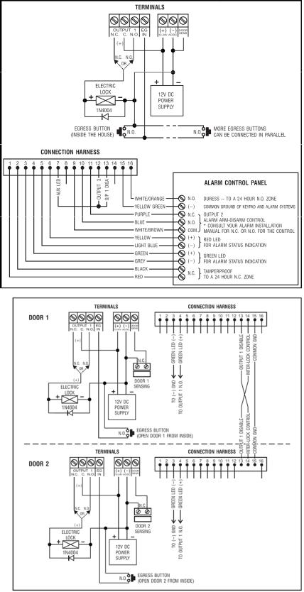
2.Basic wirings for alarm arm-disarm and stand-alone door lock (fig. 3)
∙This application is the same as application 1 except for the LED indications. The green and red LEDs are used as alarm status indications, such as exit, armed, alarm memory, etc.
∙Relay output 2 is used for the alarm arm-disarm control. Refer to the manual of your alarm control panel.
∙Connect the tamper switch to the N.C. 24-hour zone and the duress output to the N.O. 24hour zone for tamperproof and emergency reporting.
∙The connection “output 3” to “output 1 disable” is optional. With this connection, output 3 will be used as an authorization control. You may key in user code 3 to stop the operation of the electric lock at light or after office hours in order to prevent
unauthorized access. Set output 3 in start / stop mode (programming option 61) for on / off control. The red LED lights when the operation of the electric lock stops.
∙The yellow green wire is the common ground to link up the keypad and the alarm control panel in order to achieve the logical functions.
3.Basic wirings of an interlock system using 2 keypads (fig. 4)
An interlock system needs 2 door controllers. This application uses 2 x HAA85BLs with a simple crosswire
v2 15/11/2013
HAA85BL
connection on “output 1 disable” and “interlock control output” terminals of both keypads. Link up the (-) GND terminals of both keypads as common ground in order to achieve the interlock functions. Connection of the green LED is optional. It will light up when the lock is active when connected.
∙Use the keypad to open the door from the outside.
∙Press the egress button to open the door from the inside.
∙Connect the magnetic sensors on door 1 and 2.
∙During the time that door 1 is open, door 2 is forced to keep closed and vice versa.
∙Use the N.O. relay output for fail-secure locking device and the N.C. output for fail-safe locking device.
∙Relay output 2 is independent and has no concern with the interlock system. It may be used for other applications.
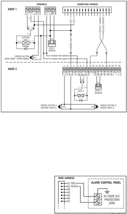
4.Basic wirings of an interlock system using 1 keypads and an interlock controller power supply (fig. 5)
This application uses one HAA85BL and a power supply with interlock controller. The power supply provides power for the whole system, including both electric locks and the keypad. Make sure the total power consumption of the system does not exceed the maximum power ratings of the power supply, especially if fail-safe locks are used. The interlock function is accomplished with a crosswire connection of the “interlock control output” and the “output 1 disable” terminals between the keypad and the controller. Link up a common ground between the keypad and the power supply to set up a power path and to achieve the interlock functions.
∙Use the keypad to open door 1 from the outside.
∙Open door 2 with egress button A from the outside while door 1 is closed.
∙Open door 1 from the inside with the egress button and open door 2 with egress button 2.
∙Connect the magnetic sensors on door 1 and 2.
∙During the time that door 1 is open, door 2 is forced to keep closed and vice versa.
∙Use the N.O. relay output for fail-secure locking device and the N.C. output for fail-safe locking device.
∙Relay output 2 is independent and has no concern with the interlock system. It may be used for other applications.
9.Application Examples for the Auxiliary Facilities
(A)Tamper N.C. (fig. 6)
The tamper switch is N.C. while the keypad is secured on the gang box. To prevent sabotage, connect these terminals in series with a N.C. 24-hour protection zone of an alarm if required.
v2 15/11/2013 |
16 |
HAA85BL
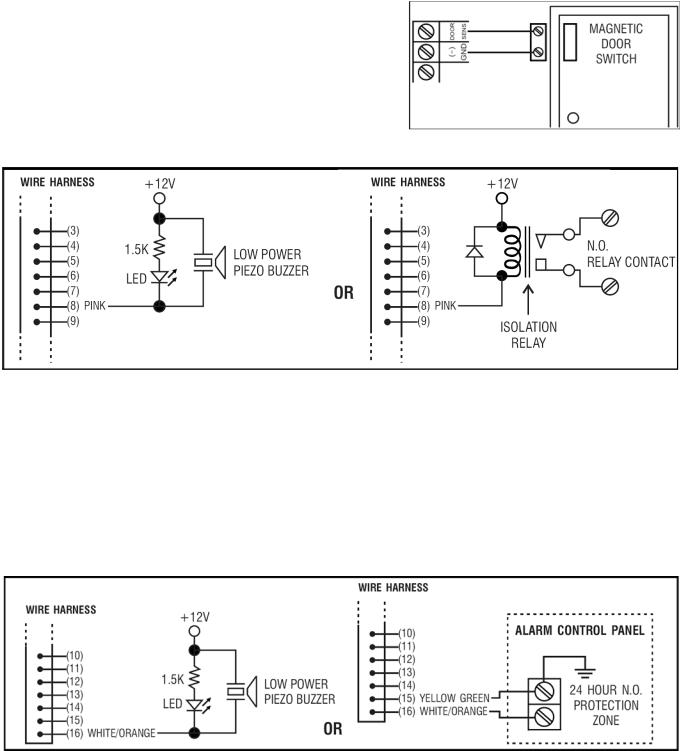
(B)Door sens (fig. 7)
With the help of a N.C. door position sensor (usually a magnetic door switch) on the door to set up the following functions: door auto relock, door forced-open alarm, door propped-up alarm and interlock control (see “2. Connections”)
(C)Key active – Pink wire (fig. 8)
The key-active output will switch to (-) ground for 10 seconds whenever a key is pressed. Use it to turn on an LED lamp and/or a small buzzer to notify a guard, to energize a relay to switch on lights or a CCTV camera…
∙Make sure that the relay for switching on the lights has enough isolation between the high-voltage and lowvoltage to prevent damage to the keypad.
∙Only one connection option is recommended. Make sure the sink current does not exceed the maximum rating of 100mA.
∙External power supply and isolation relay are necessary for driving high-power devices such as lights.
(D)Duress output – White/orange wire (fig. 9)
The duress output will switch to (-) ground when the duress code is entered. You may use it to turn on an LED lamp and/or a small buzzer. Connect it to a N.C. 24-hour protection zone of an alarm system.
∙Only one connection option is recommended. Make sure the sink current does not exceed the maximum rating of 100mA.
(E)Output 2
1. Shunting an N.C. zone (white/brown and blue wires) (fig. 10)
v2 15/11/2013 |
17 |
VELLEMAN |
HAA85BL
∙Use the N.O. output contact to shunt a N.C. protection zone of an alarm system.
∙Set the output contact to start / stop mode (programming option 51).
2.Alarm system arm-disarm control (white/brown and blue or purple wires) (fig. 11)
∙Use the N.O. or the N.C. output contact to set the alarm system in arm-disarm mode.
∙Refer to the manual of your alarm control panel for the appropriate output contact to be used in armdisarm control.
∙Usually set output 2 to momentary mode (programming option 501) for multi-station systems and start / stop mode (programming option 51) in single-station systems.
(F)Output 3 (white/red wire) (fig. 12)
Output 3 is an open collector output prepared for auxiliary controls. It may be used for arm-disarm of a security system, enabling and disabling of a keypad or a protection zone, etc. It can also drive a relay to give full function of N.C. and N.O. outputs.
For more info concerning this product, please visit our website www.velleman.eu. The information in this manual is subject to change without prior notice.
v2 15/11/2013 |
18 |
VELLEMAN |

HAA85BL
GEBRUIKERSHANDLEIDING
1. Inleiding en kenmerken
Aan alle ingezetenen van de Europese Unie Belangrijke milieu-informatie betreffende dit product
Dit symbool op het toestel of de verpakking geeft aan dat, als het na zijn levenscyclus wordt weggeworpen, dit toestel schade kan toebrengen aan het milieu.
Gooi dit toestel (en eventuele batterijen) niet bij het gewone huishoudelijke afval; het moet bij een gespecialiseerd bedrijf terechtkomen voor recyclage.
U moet dit toestel naar uw verdeler of naar een lokaal recyclagepunt brengen. Respecteer de plaatselijke milieuwetgeving.
Hebt u vragen, contacteer dan de plaatselijke autoriteiten inzake verwijdering.
Dank u voor uw aankoop! Lees deze handleiding grondig voor u het toestel in gebruik neemt. Werd het toestel beschadigd tijdens het transport, installeer het dan niet en raadpleeg uw dealer.
De HAA85BL is een onafhankelijk en betrouwbaar beveiligingstoetsenbord (met achtergrondverlichting) aan een zacht prijsje en kan gebruikt worden in zowel woningen als bedrijven. Dit toetsenbord is compatibel met vrijwel elk elektronisch slot in beveiligingssystemen, automatische schakelingen en machines. Er zijn meer dan 100 miljoen combinaties mogelijk voor de gebruikerscodes (multi-usercode). De gegevens worden in een niet-vluchtig geheugen bewaard. Enkel voor gebruik binnenshuis.
Toetsenbord met achtergrondverlichting: zwak in stand-by, sterk gedurende 10 seconden na indrukken van een toets.
2. Aansluitingen (zie fig. 1)
DE LED-AANDUIDINGEN
∙ROOD & GROEN
Verbind de rode en de groene leds naar goeddunken.
∙AUX ROOD / GROEN
De groene led is een statusaanduiding tijdens de normale werking. De led verandert naar vast rood terwijl de AUX rode led wordt geactiveerd.
HET AANSLUITBLOK
∙OUTPUT 1
5A droog relaiscontact voor een deurschakelaar. Normaal open (N.O.) en normaal gesloten (N.C.) uitgangen zijn verkrijgbaar. Gebruik de N.O.-uitgang voor een slot in arbeidsstroom (fail-secure) en een N.C.-uitgang voor een slot in ruststroom (fail-safe). Het relais kan worden geprogrammeerd in start-stopmodus (schakeling) of timermodus van 1 tot 999 seconden.
∙EG IN (EGRESS-ingang)
Een N.O.-ingangsterminal wordt aangesloten op de (-) aarding door middel van een N.O.-toets om relaisuitgang 1 te deactiveren. De egress-toets wordt doorgaans binnenshuis naast de deur geplaatst. U kunt meer dan één egress-toets parallel aan de terminal aansluiten. Laat de aansluiting open wanneer u deze niet gebruikt.
∙12V-24V AC/DC (VOEDINGSINGANG)
Sluit een 12V-24V AC/DC voeding aan. De (-) klem en de GND (aarding, kabel 15) zijn gemeenschappelijke aardingspunten. Er is geen brug nodig voor het gehele bereik van de ingangsspanning. Verbind de gelijkspanning met de (+) en de (-); er is geen onderscheid voor de wisselspanning.
v2 15/11/2013 |
19 |
VELLEMAN |
HAA85BL
∙DOOR SENS (INGANG VAN DE DEURSENSOR)
Een N.C.-ingangsterminal aangesloten op de (-) aarding. Samen met een N.C. magnetische deurschakelaar zal het systeem de stand van de deur bepalen en volgende functies geven:
1.Automatische deurvergrendeling
Het systeem vergrendelt automatisch de deur na het ingeven van een geldige code vóór het einde van de programmeertijd voor uitgang 1.
2.Alarm bij geforceerde deur
Het systeem genereert onmiddellijk een alarmsignaal wanneer de deur wordt geforceerd zonder een geldige gebruikerscode of egress-ingang. Het alarmsignaal duurt 60 seconden en kan worden onderbroken met gebruikerscode 1 of één van de gebruikerscodes in groep 1. Deze functie is selecteerbaar via de programmeeropties op locatie 801.
3.Alarm bij open deur
Alarm wanneer de deur langer dan de toegestane tijd open blijft staan, m.a.w. het alarm gaat af na het verlopen van de ingestelde tijd tot de deur opnieuw wordt gesloten. De tijd is instelbaar van 1 tot 999 seconden op locatie 9.
4.Sassysteem
Aansluiting op (-) terwijl de deur open is zodat het signaal wordt gegeven om de andere deur van het
sassysteem te openen.
DE KABELBOOM
OPMERKING: Houd de printplaat stevig vast en trek voorzichtig aan de plug zodat u de elektronica niet beschadigd.
∙N.C. TAMPER (1-2)
N.C.-contact wanneer het toetsenbord aan de doos bevestigd is. Het wordt geopend wanneer het frontpaneel van de doos verwijderd wordt. Sluit deze uitgang in serie aan de 24-uur noodschakeling op uw alarmsysteem indien gewenst.
∙GROENE, RODE & AUX RODE LEDS (3-4), (5-6) & (7)
Er zijn 3 leds op het paneel voorhanden. Ze werden voorbereid om er om het even welke functie op aan te sluiten. Wij stellen voor om deze leds aan de indicatieaansluitingen van uw alarmcontrole paneel aan te sluiten. Houd de juiste polariteit in het oog.
De groene en de rode onafhankelijke leds zijn voorzien van een 1.5k Ω stroombeperkende weerstand.
De anode van de AUX rode led wordt intern aangesloten op de +5V en wordt ingeschakeld met de kathode (kabel 7) aangesloten op de (-) aarding.
∙ACTIEVE UITGANG OF ALARMUITGANG (8)
Opencollectoruitgang van een NPN transistor van max. 100mA sink en 24VDC. Selecteerbaar via de K- of A- jumper voor de actieve uitgang of alarmuitgang.
1.Actieve uitgang (KEY)
Schakelt gedurende 10 seconden naar de (-) aarding bij elke druk op de toets. Wordt gebruikt voor het inschakelen van verlichting, CCTV-camera’s of zoemers.
2.Alarmuitgang (AL)
Schakelt naar de (-) aarding wanneer het alarm bij geforceerde of open deur afgaat. Zo wordt een extern alarm ingeschakeld.
∙UITGANG 2 (9-10-11)
v2 15/11/2013 |
20 |
VELLEMAN |
HAA85BL
Supplementaire relaisuitgang met 1A N.O. en N.C. droge contacten sie met gebruikerscode 2 worden aangestuurd. Ideaal voor het aansturen van veiligheidssystemen en automatische machines. Het relais kan worden geprogrammeerd in start-stopmodus (schakeling) of timermodus van 1 tot 999 seconden.
∙UITGANG 3 (12)
Opencollectoruitgang van een NPN transistor en ideaal voor het aansturen van veiligheidssystemen. Deze uitgang kan worden geprogrammeerd in start-stopmodus (schakeling) of timermodus van 1 tot 999 seconden. De uitgang schakelt naar de (-) aarding wanneer actief. Max. 100mA sink / 24VDC.
∙UITSCHAKELING UITGANG 1 (13)
Een N.O.-ingangsaansluiting wordt aangesloten op de (-) aarding. Noch gebruikerscode 1 noch de egress-knop kan uitgang 1 inschakelen. Klaar voor en gekruiste aansluiting voor gebruik in een sassysteem.
∙UITGANG SASSYTEEM (14)
Opencollectoruitgang van een NPN transistor. Is normaal uitgeschakeld en schakelt onmiddellijk naar de (-) aarding nadat een geldige gebruikerscode werd ingetoetst. Blijft aangesloten op (-) zolang de deursensor open is. Gebruik deze uitgang om het andere toetsenbord in een sassysteem aan te sturen en om te vermijden dat beide deuren gelijktijdig geopende kunnen worden.
∙DURESS-UITGANG (16)
Opencollectoruitgang van een NPN transistor. Schakelt naar de (-) aarding wanneer de duress-code wordt ingegeven. Gebruik deze uitgang het alarm in te schakelen. Ic max.: 100mA sink; Vc max.: 24VDC.
3. Geluidssignalen en led-aanduidingen
De ingebouwde zoemer en de groene led in het midden geven volgende signalen weer:
|
STATUS |
SIGNAAL* |
LED-SIGNAAL |
1. |
In programmeerbare modus |
- - - |
ON |
2. |
Toets is goed ingedrukt |
1 pieptoon |
1 flits |
3. |
Code is juist ingetoetst |
2 pieptonen |
2 flitsen |
4. |
Code is fout ingetoetst |
5 pieptonen |
5 flitsen |
5. |
DAP jumper niet opnieuw geplaatst |
Continue pieptonen |
Continue flitsen |
6. |
In stand-by modus |
- - - |
1 flits in interval van 2 seconden |
7. |
Relaisuitgang ingeschakeld |
Pieptoon van 1 seconde** |
- - - |
OPMERKINGEN: * Alle geluidssignalen kunnen ge(de)activeerd worden door de opties op locatie 83 te programmeren.
**De pieptonen kunnen ge(de)activeerd worden door de opties op locatie 82 te programmeren.
4.Mastercode resetten
Bent u de mastercode vergeten, dan kunt u deze resetten. Gebruik voor het programmeren van de mastercode, geen combinatie die reeds toegekend is aan een gebruikerscode.
1.Koppel de voedingsspanning los.
2.Verander de DAP jumper van OFF naar ON.
3.Koppel de voedingsspanning terug aan. (de zoemer weerklinkt).
4.Plaats de DAP jumper terug in de OFF positie (wanneer dit gebeurd is, zal de zoemer niet meer weerklinken).
5.Het toetsenbord is nu in programmeermode en is klaar om het nieuwe programmaatje te ontvangen.
6.Toets een nieuw, 4-cijferige meestercode in op locatie 0 indien de oude meestercode vergeten werd.
7.Toets het nieuwe programma in, startend vanaf punt B) in het hiernavolgend deel “PROGRAMMEREN VAN HET TOETSENBORD”.
v2 15/11/2013 |
21 |
VELLEMAN |
HAA85BL
5. De meestercode van de fabrikant – Belangrijke opmerking
Bij de eerste programmering gebruikt u best 0000 als meestercode. Programmeer nadien een nieuwe meestercode.
6.Programmeren van het toetsenbord – Hoofdtabel
A)Gebruik de meestercode van de fabrikant om in de programmeermodus te komen – Enkel bij de eerste programmering
Invoer |
Bevestiging Commentaar |
|
Toegang in de programmeermode d.m.v. de meestercode van de |
|
fabrikant |
B) Instellen van de single of multi-usermodus en herstarten van het systeem – Installatieprogrammering
Invoer |
Bevestiging Commentaar |
|
Instellen van de single gebruikersmodus, wissen van alle |
|
opgeslagen data en herstarten van het systeem |
|
Instellen van de multi-user gebruikersmodus, wissen van alle |
|
opgeslagen data en herstarten van het systeem |
C)Opnemen van de persoonlijke meesteren gebruikerscodes – Gebruikersprogrammering Opmerkingen: mastercode
∙Programmeer eerst de mastercode en daarna de gebruikerscodes.
∙Gebruik voor het programmeren van een nieuwe mastercode, geen combinatie die reeds toegekend is aan een gebruikerscode.
∙Bent u de mastercode vergeten, dan kunt u deze resetten. Zie 4. Mastercode resetten.
Opmerkingen: gebruikerscode
∙De gebruikercodes moeten verschillend zijn van de mastercode.
∙Programmeer een andere code voor elke gebruiker.
1.Single user – Cijfers mogen herhaald worden
Locatie |
Invoer |
Bevestiging |
Commentaar |
|
4 cijfers, vast |
|
Persoonlijke meestercode en supergebruikerscode |
|
4 cijfers, vast |
|
Gebruikerscode 1 voor uitgang 1 met duress-code |
|
4 cijfers, vast |
|
Gebruikerscode 2 voor uitgang 2 |
|
4 cijfers, vast |
|
Gebruikerscode 3 voor uitgang 3 |
2. Multi-user – Cijfers mogen herhaald worden |
|||
Locatie |
Gebruiker |
Invoer |
Bevestiging Commentaar |
|
|
4 tot 8 cijfers |
Persoonlijke meestercode en |
|
|
supergebruikerscode |
|
|
|
|
|
|
00 tot 99 |
4 tot 8 cijfers |
100 gebruikerscodes in groep 1 voor |
|
uitgang 1 met duress-code |
||
|
|
|
|
v2 15/11/2013 |
22 |
VELLEMAN |
HAA85BL
|
0 tot 9 |
4 tot 8 cijfers |
|
0 tot 9 |
4 tot 8 cijfers |
D) |
van de uitgangsmodi – Installatieprogrammering |
|
10 gebruikerscodes in groep 2 voor uitgang 2
10 gebruikerscodes in groep 3 voor uitgang 3
|
|
|
Tijdsduur |
Bevestiging |
Commentaar |
|
|
|
1 tot 999s |
|
Uitgang 1 momentmodus van 1 tot 999 seconden |
|
|
|
|
|
Uitgang 1 in start-stopmodus (schakeling) |
|
|
|
|
|
Uitgang 1 in start-stopmodus met verkorte code |
|
|
|
|
|
|
|
|
|
1 tot 999s |
|
Uitgang 2 momentmodus van 1 tot 999 seconden |
|
|
|
|
|
Uitgang 2 in start-stopmodus (schakeling) |
|
|
|
|
|
Uitgang 2 in start-stopmodus met verkorte code |
|
|
|
|
|
|
|
|
|
1 tot 999s |
|
Uitgang 3 momentmodus van 1 tot 999 seconden |
|
|
|
|
|
Uitgang 3 in start-stopmodus (schakeling) |
|
|
|
|
|
Uitgang 3 in start-stopmodus met verkorte code |
E) |
|
veiligheid – Installatieprogrammering |
|||
|
|
|
Aantal foute |
Bevestiging |
Commentaar |
|
|
|
codes |
||
|
|
|
|
Na 10 opeenvolgende foute codes wordt het |
|
|
|
|
|
|
|
|
|
|
|
|
toetsenbord vergrendeld gedurende 30 seconden |
|
|
|
|
|
Na 10 opeenvolgende foute codes schakelt de duress- |
|
|
|
|
|
uitgang naar de aarding |
|
|
|
5 tot 10 |
|
Na 5 tot 10 foute codes wordt het toetsenbord |
|
|
|
|
|
gedurende 15 minuten vergrendeld. Het toetsenbord |
|
|
|
|
|
kan gedurende deze tijd enkel met de meestercode |
|
|
|
|
|
worden ontgrendeld. |
|
|
00 |
|
Alle bovenvermelde instellingen verdwijnen |
|
|
|
|
|
|
|
F) |
geforceerde deur – Installatieprogrammering |
||||
|
|
|
Functiecode |
Bevestiging |
Commentaar |
|
|
|
|
|
Inschakeling alarm bij geforceerde deur |
|
|
|
|
|
Uitschakeling alarm bij geforceerde deur |
G) |
|
geactiveerde uitgang – Installatieprogrammering |
|||
|
|
|
Functiecode |
Bevestiging |
Commentaar |
|
|
|
|
|
Pieptoon van 1 seconde die aankondigt dat de deur is |
geopend en het uitgangsrelais is geactiveerd met een gebruikerscode of de egress-knop. Ideaal voor een geruisloos slot zoals een magnetisch slot.
Pieptoon uitgeschakeld en vervangen door 2 korte pieptonen bij juiste invoer.
v2 15/11/2013 |
23 |
VELLEMAN |
HAA85BL
H) Invoermodus van de gebruikerscode (auto of manueel) – Installatieprogrammering
Locatie |
Functiecode |
Bevestiging Commentaar |
|
|
|
|
Automatische code-invoer. |
hoeft na de invoer niet |
|
|
|
ingedrukt te worden. De gebruikerscode MOET |
||
|
|
evenveel digits bevatten als de meestercode (4 tot 8 |
||
|
|
digits). |
|
|
|
|
Manuele code-invoer. |
moet na de invoer ingedrukt |
|
worden. De gebruikerscodes kunnen 4 tot 8 digits lang zijn maar hoeven niet evenveel digits te bevatten als de meestercode.
OPMERKING: In single gebruikersmodus moeten zowel de gebruikerscode als de meestercode 4 digits bevatten, ongeacht de invoermodus (auto of manueel).
I) Geluidssignalen – Installatieprogrammering
Locatie |
Functiecode |
Bevestiging Commentaar |
|
|
Geluidssignalen geactiveerd. |
|
|
Alle geluidssignalen uitgeschakeld. |
J) Tijdsinstelling van het alarm bij open deur – Installatieprogrammering
Locatie |
Functiecode |
Bevestiging Commentaar |
|
0 |
Geen alarm |
|
1 tot 999 |
Tijdsinstelling van 1 tot 999 seconden alvorens het |
|
alarm bij open deur weerklinkt. |
|
|
|
K) De programmeermodus verlaten
Bevestiging Commentaar
Verlaat de programmeermodus en keer terug naar de normale werkmodus.
7. Selecteren van de single of multi-usermodus
Uw HAA85BL werd ingesteld op single gebruikersmodus met  als meestercode.
Single gebruikersmodus (code: 8900)
Elke uitgang kan slechts door één gebruikerscode bediend worden. De gebruikerscode moet 4 digits bevatten. Er zijn zo’n 10 000 mogelijke combinaties. De code wordt direct in de locaties 1, 2 en 3 voor de respectievelijke 3 uitgangen geprogrammeerd. Zie “6. C) 1. Single user – Cijfers mogen herhaald worden” voor meer details. Deze modus wordt standaard met automatische code-invoer geconfigureerd. Toets enkel de 4-cijferige code in,
 hoeft niet ingedrukt te worden.
OPMERKING: Stel de manuele code-invoer in door programmeeroptie 0 op locatie 82 te kiezen indien gewenst.
Multi-user gebruikersmodus (code: 8901)
Uitgang 1 wordt door 100 individuele codes bediend terwijl uitgang 2 en 3 elk door 10 individuele codes bediend kunnen worden. De gebruikerscode is 4 tot 8 digits lang. Er zijn zo’n 100 miljoen mogelijke combinaties. Kies voor
v2 15/11/2013 |
24 |
VELLEMAN |
HAA85BL
de automatische of de manuele code-invoer via de programmeeropties op locatie 82. De manuele code-invoer is de standaardmodus.  moet na de invoer ingedrukt worden. De meestercode en de gebruikerscode moeten beiden hetzelfde aantal digits bevatten wanneer het toetsenbord in automatische code-invoer is geprogrammeerd. Druk niet op
  na het invoeren van de gebruikerscode in automatische code-invoer.
Defaultwaarden
Default |
Commentaar |
Default |
Commentaar |
401 |
Uitgang 1 in momentmodus van 1 |
811 |
Pieptoon uitgangsrelais ingeschakeld |
|
seconde |
|
|
501 |
Uitgang 2 in momentmodus van 1 |
820 |
Manuele invoer gebruikerscode * (multi- |
|
seconde |
|
user gebruikersmodus) |
601 |
Uitgang 3 in momentmodus van 1 |
821 |
Manuele invoer gebruikerscode * (single |
|
seconde |
|
gebruikersmodus) |
70 |
Blokkering van 30 seconden na invoer |
831 |
Geluidssignalen ingeschakeld |
|
van 10 opeenvolgende foute codes |
|
|
800 |
Alarm bij geforceerde deur |
90 |
Geen alarm bij open deur |
|
uitgeschakeld |
|
|
OPMERKING: * Alle defaultwaarden in de multi-user en single gebruikersmodi zijn identiek uitgenomen de invoermodus van de gebruikerscode.
Beperkingen van de code-invoer te wijten aan de duress-code
Het systeem heeft een duress-functie voor code 1 in single gebruikersmodus en alle gebruikerscodes voor groep 1 in multi-usermodus. De duress-code wordt automatisch door het systeem geconfigureerd: gebruikerscode +2 of -2. Om te vermijden dat andere codes de duress-code overlappen, is een andere gebruikerscode met als eerste cijfer het eerste cijfer van de opgeslagen gebruikerscode +2 of -2 niet toegelaten.
Voorbeeld: Gebruikerscode 56789 werd opgeslagen. Gebruikerscodes 36789 en 76789 mogen dus niet gebruikt worden.
Selecteren van de single gebruikersmodus
U kunt de single gebruikersmodus instellen met code 8900. Het toetsenbord blijft in deze modus tot u het systeem vernieuwt. Zorg er wel voor dat de meestercode 4 digits lang is.
MEESTER
Single gebruikersmodus ingeschakeld. Wacht 2-3
CODE seconden na het indrukken van tot u een bevestigende pieptoon hoort.
Selecteren van de multi-user gebruikersmodus
U kunt de multi-user gebruikersmodus instellen met code 8901. Het toetsenbord blijft in deze modus tot u het systeem vernieuwt.
MEESTER
Multi-user gebruikersmodus ingeschakeld. Wacht 2-3
CODE seconden na het indrukken van tot u een bevestigende pieptoon hoort.
Het systeem vernieuwen
Bij het selecteren van een nieuwe gebruikersmodus (zie hierboven) zal het systeem alle waarden wissen met uitzondering van de meestercode.
v2 15/11/2013 |
25 |
VELLEMAN |
HAA85BL
OPMERKING: Zorg ervoor dat, wanneer u in single gebruikersmodus bent, zowel de meestercode en de gebruikerscode 4 digits lang zijn.
8.Het toetsenbord programmeren en gebruiken – Voorbeeld
A)Procedures
a.De programmering van uw HAA85BL gebeurt volledig vanaf het toetsenbord. Alle geprogrammeerde waarden worden in het niet-vluchtige geheugen opgeslagen.
b.Plaats het toetsenbord eerst in de programmeermodus met behulp van de meestercode en druk op  om te bevestigen.
OPMERKING: Gebruik de DAP jumper en plaats het toetsenbord in de programmeermodus mocht de meestercode vergeten zijn. Zie 4. Mastercode resetten.
c.Ga naar de locatie en programmeer de opties. Zie “6. Programmeren van het toetsenbord – Hoofdtabel”.
d.Programmeer alle opties. Herhaal indien fout ingegeven.
LOCATIE 1
…
LOCATIE n
OPTIE
OPTIE n
e.Verlaat de programmeermodus met  . Alle ingevoerde waarden worden opgeslagen.
B)Single gebruikersmodus – Voorbeeld
1.Vereisten
a.Single gebruikersmodus
b.Wijziging van de default meestercode 0000 naar een persoonlijke meestercode 3289
c.Stel gebruikerscode 1 op 8321
d.Stel gebruikerscode 2 op 6854
e.Stel gebruikerscode 3 op 9270
f.Stel uitgang 1 in momentmodus, 1 seconde
g.Stel uitgang 2 in start-stopmodus
h.Stel uitgang 3 op start-stopmodus
i.Stel het toetsenbord in om, na 10 foute codes, gedurende 15 minuten te blokkeren
2.Programmeren – Ingeven van de gegevens hierboven in het toetsenbord
Programmeermodus met default meestercode
Single gebruikersmodus*
3289 opgeslagen als nieuwe persoonlijke meestercode en supergebruikerscode
8321 opgeslagen als gebruikerscode 1 met duress-functie voor uitgang 1
6854 opgeslagen als gebruikerscode 2 voor uitgang 2
9270 opgeslagen als gebruikerscode 3 voor uitgang 3
Uitgang 1 ingesteld als momentmodus, 1 seconde
v2 15/11/2013 |
26 |
VELLEMAN |
 Loading...