


400W MONO/STEREO AMPLIFIER
|
|
|
|
|
|
|
|
|
|
|
|
|
s to |
|
|
|
|
|
|
|
|
|
|
|
|
rd |
|
|
|
|
|
|
|
|
|
|
|
ct |
are the wo |
|
|
|
|
|
|
|
|
|
|
|
pa |
|
|
|
|
|
|
|
|
|
|
|
|
om |
|
|
|
|
|
|
|
|
|
|
|
|
d c |
|
|
|
|
|
|
|
|
|
|
st |
|
an |
|
|
|
|
|
|
|
|
|
|
bu |
|
|
|
|
|
|
|
|
|
|
|
|
al, |
ro |
|
|
|
|
|
|
|
|
r. |
|
|
rs |
|
|
|
|
|
|
|
|
fie |
|
||
ive |
|
|
|
|
|
|
|
|
pli |
|
|
||
Un |
|
|
|
|
|
|
|
is |
am |
|
|
|
|
|
|
|
|
|
|
e th |
|
|
|
|
|
||
|
|
|
|
|
rib |
|
|
|
|
|
|
|
|
|
|
|
|
sc |
|
|
|
|
|
|
|
|
|
|
|
|
de |
|
|
|
|
|
|
|
|
|
|
Total solder points: 264
Difficulty level: beginner 1 2 3 4 5 advanced
K4005B
ILLUSTRATED ASSEMBLY MANUAL |
H4005B-IP-2 |

Features & specifications
Features:
Rms output power : 2 x 100W / 4ohm ; 2 x 75W / 8ohm.
Rms mono-bridged power : 200W / 8ohm.
Total music output : 400W.
Harmonic distortion : 0.003% at 1KHz.
Signal-to-noise ratio : 96dB (A-weighted).
Stereo channel separation : 76dB.
Damping factor (at 100Hz) : > 2000.
Specifications:
•Input impedance : 22kohm .
•Input sensitivity : 150mV, 300mV or 950mV switchable .
•Supply voltage for 8 ohm : + 35 to 40VDC and - 35 to 40VDC / 2.5A.
•Supply voltage for 4 ohm or mono: + 25 to 30VDC and - 25 to 30VDC/ 5A
•Dimensions : 350 x 62 x 85mm (13.8" x 2.5" x 3.4").
modifications reserved
2
Assembly hints
1. Assembly (Skipping this can lead to troubles ! )
Ok, so we have your attention. These hints will help you to make this project successful. Read them carefully.
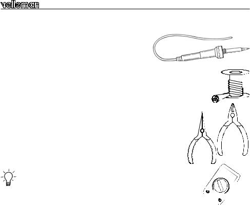
1.1 Make sure you have the right tools:
•A good quality soldering iron (25-40W) with a small tip.
•Wipe it often on a wet sponge or cloth, to keep it clean; then apply solder to the tip, to give it a wet look. This is called ‘thinning’ and will protect the tip, and enables you to make good connections. When solder rolls off the tip, it needs cleaning.
• Thin raisin-core solder. Do not use any flux or grease.
•A diagonal cutter to trim excess wires. To avoid injury when cutting excess hold the lead so they cannot fly towards the eyes.
•Needle nose pliers, for bending leads, or to hold components in place.
•Small blade and Phillips screwdrivers. A basic range is fine.
For some projects, a basic multi-meter is required, or might be handy
l e a d s ,
0 |
|
. |
|
0 |
|
|
0 |
|
0 |
1.2 Assembly Hints :
Make sure the skill level matches your experience, to avoid disappointments.
Follow the instructions carefully. Read and understand the entire step before you perform each operation.
Perform the assembly in the correct order as stated in this manual
Position all parts on the PCB (Printed Circuit Board) as shown on the drawings.
Values on the circuit diagram are subject to changes.
Values in this assembly guide are correct*
Use the check-boxes to mark your progress.
Please read the included information on safety and customer service
* Typographical inaccuracies excluded. Always look for possible last minute manual updates, indicated as ‘NOTE’ on a separate leaflet.
3
Assembly hints
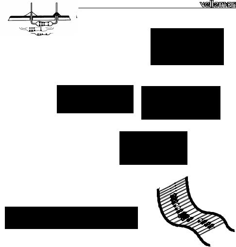
1.3 Soldering Hints :
1- Mount the component against the PCB surface and carefully solder the leads
2- Make sure the solder joints are cone-shaped and shiny
3- Trim excess leads as close as possible to the solder joint
REMOVE THEM FROM THE TAPE ONE AT A TIME !
AXIAL COMPONENTS ARE TAPED IN THE CORRECT MOUNTING SEQUENCE !
4

Construction
1. Jumpers
J : 8X
Choice between different input sensitivities :
Mount the jumpers JH for a sensitivity of 950mV.
Mount the jumpers JM for a sensitivity of 500mV.
Leave both jumper connections OPEN for a sensitivity of 150mV.
A bipolair THREE POSITION switch may be mounted here as well!
Choice between stereo or mono :
Mount the jumpers JS for a stereo amplifier.
Mount the jumpers JB for a mono-bridged amplifier.
Here a unipolar change-over switch may be mounted as well!
JH JM
JH JM
JH JM
JH JM
JH JM
JH JM
JB |
JS |
JB |
JS |
JB |
JS |
JB |
JS |
2. Diodes. Watch the polarity!
D...
CATHODE
D1 : 1N5404
D2 : 1N5404
3. Zener diodes. Watch the polarity!
ZD...
CATHODE
ZD1 : 15V0
ZD2 : 15V0
4. 1/4W Resistors
R...
R1 |
: |
22K |
(2 - 2 - 3 - B) |
R2 |
: |
22K |
(2 - 2 - 3 - B) |
R3 |
: |
22K |
(2 - 2 - 3 - B) |
R4 |
: |
22K |
(2 - 2 - 3 - B) |
R5 |
: |
22K |
(2 - 2 - 3 - B) |
R6 |
: |
22K |
(2 - 2 - 3 - B) |
R7 |
: |
22K |
(2 - 2 - 3 - B) |
R8 |
: |
2K2 |
(2 - 2 - 2 - B) |
R9 |
: |
1K8 |
(1 - 8 - 2 - B) |
R12 |
: |
47K |
(4 - 7 - 3 - B) |
R13 |
: |
120K |
(1 - 2 - 4 - B) |
5
 Loading...