


Extended USB interface card
|
|
|
|
|
|
|
|
|
|
|
|
|
|
|
B |
|
|
|
|
|
|
|
|
|
|
|
|
|
|
|
|
|
|
|
|
|
|
|
|
|
|
|
|
|
|
|
|
sal |
US |
|
|
|
|
|
|
|
|
|
|
|
|
|
|
iver |
|
|
|
|
|
|
|
|
|
|
|
|
|
|
|
O |
un |
|
|
|
|
|
|
|
|
|
|
|
|
|
|
3I/ |
|
|
|
|
|
|
|
|
|
|
|
|
|
|
|
l 3 |
|
|
|
|
|
|
|
|
|
|
|
|
|
|
efu |
|
|
|
|
|
|
||
|
|
|
|
|
|
|
|
us |
|
|
|
|
|
|
|
|
|
|
|
|
|
|
lly |
|
|
|
|
|
|
|
|
|
|
|
|
|
|
|
ca |
|
|
|
|
|
|
|
|
|
|
|
|
|
|
|
cti |
|
|
|
|
|
|
|
|
|
|
|
|
|
|
|
ra |
|
|
|
|
|
|
|
|
. |
|
|
|
|
|
|
A |
p |
|
|
|
|
|
|
|
|
|
|
|
|
|
|
|
|
|
|
|
|
|
|
|
|
ard |
|
|
|
||
|
|
|
|
|
|
|
|
|
|
ce |
bo |
|
|
|
|
|
|
|
|
|
|
|
|
|
|
rfa |
|
|
|
|
|
|
|
|
|
|
|
|
|
|
inte |
|
|
|
|
|
|
|
||
|
|
|
|
|
|
|
|
|
|
|
|
|
|
|
|
|
|
|
|
|
|
|
|
|
|
|
|
|
|
|
|
|
|
VM140
EXTENDED USB INTERFACE BOARD |
3 |
UITGEBREIDE USB INTERFACEKAART |
10 |
INTERFACE USB - VERSION ETENDUE |
17 |
ERWEITERTE USB-SCHNITTSTELLENKARTE |
24 |
INTERFACE USB DE GRAN EXTENSIÓN |
31 |

Velleman Components N.V.
Legen Heirweg 33
9890 Gavere, Belgium
http://www.velleman-kit.com
Kits & Instruments Service Forum : http://forum.velleman.be

Features & specifications
This computer interface board has a total of 33 inputs / outputs, including analogue / digital and a
PWM output.
The connection to the computer via the USB port is galvanically-optically isolated, so that damage to the computer is impossible thus providing a high level of secure implementation.
All communication routines are contained in a Dynamic Link Library (DLL).
You may write custom Windows* Applications in Borland Delphi, Borland C++ Builder, Microsoft Visual Basic, Microsoft VC or most other 32-bit Windows application development tool that supports calls to a DLL.
FEATURES:
8 analogue 10 bit resolution inputs: 0…5 or 10VDC / 20k ohms
8 analogue 8 bit resolution outputs: 0…5V or 10VDC / 47 ohms
8 digital inputs: open collector compatible (connection to GND=0) with on-board LED indication
8 digital open collector outputs (max. 50V/100mA) with on-board LED indication
one 10 bit PWM output: 0 to 100% open collector output (max 100mA / 40V) with on-board LED indication
USB port: USB 1.1 & 2.0 compatible
SPECIFICATIONS:
∙power consumption through USB port: approx. 60mA
∙up to 8 cards can be connected to PC
∙power supply through adapter: 12VDC / 300mA (PS1205)
∙PWM frequency: 15.6kHz
∙command execution time: between 21 and 48ms
∙PCB dimensions: 195 x 142 x 20mm (2.7 " x 5.6" x 0.8")
MINIMAL SYSTEM REQUIREMENTS:
∙Pentium class CPU or higher with free USB port (1.1 or higher)
∙Microsoft Windows 2000 or Windows XP*
∙CD-ROM player and mouse
*WinXp recommended for optimum compatibility
*Are registered trademarks of MICROSOFT CORP.
3

4
19
12
3
8
4
 5
5
15
 6
6
16
 20
20
13
7
17
10
9
11
14
18
1
Connections |
Connections |
2

Connections
1
2
3
4
5
6
7
8
9
10
11
12
13
14
15
16
17
18
19
20
USB-connector |
Connection of the VM140 with the USB port of your PC |
|
|
|
|
12VDC |
Power supply connection. Connect a 12V non-regulated adapter supplying |
|
min. 300mA |
||
|
||
|
|
|
Digital inputs |
|
|
1, 2, 3, 4 |
Inputs need to go “LOW” externally to activate (connect with the GND). |
|
Digital inputs |
||
|
||
5, 6, 7, 8 |
|
|
|
|
|
Digital outputs |
These outputs are open collector outputs. When active, the transistors in IC4 |
|
1, 2, 3, 4 |
will conduct and a “connection” will be established between GND and the |
|
|
output in question. The charge you wish to feed, like a LED, relay …, must |
|
Digital outputs |
receive an external tension. Connect the “CLAMP” connection with the + of |
|
this external power supply so as to protect the transistor array. |
||
5,6,7,8 |
||
|
||
|
|
|
Analogue inputs |
These are measuring points with which you can digitalize and read out an |
|
1,2,3,4 |
analogue voltage through the PC. The analogue inputs expect a DC voltage |
|
|
between 0 and 5V or between 0 and 10V. Select with the jumpers AD1 to AD8 |
|
Analogue inputs |
||
(see n° 13). Attention: Supplying a voltage to the A/D inputs higher than 5 or |
||
5,6,7,8 |
10V can cause irrevocable damage to the VM140 (IC10/11)! |
|
|
|
|
Analogue outputs |
Determination with software of the DC voltage on these outputs. Depending |
|
1,2,3,4 |
on the jumpers DA1 to DA8 you can establish this voltage between 0 and 5V |
|
|
or between 0 and 10V. On pin 2 of this connector (SK9) you can also find the |
|
Analogue outputs |
||
PWM output. The PWM output is an open collector output whose pulse width |
||
5,6,7,8 |
is adjustable. |
|
|
|
|
Addressing of the |
With the jumpers A1, A2 and A3 you can attribute a unique address to each |
|
connected VM140. Up to 8 boards can be connected. If you have only 1 |
||
selection jumpers |
||
VM140, establish its address as “0”. |
||
|
||
|
|
|
Max. A/D voltage |
With the jumpers AD1-AD8 you can select the voltage range for the corre- |
|
sponding A/D inputs between 0 to 5V (closed) or 0 to 10V (open). |
||
|
||
|
|
|
Max. D/A output |
With the jumpers DA1-DA8 you can select the max. voltage range for the |
|
voltage |
corresponding D/A outputs between 0 to 5V (open) or 0 tot 10V (closed) |
|
|
|
|
PWM control LED |
This LED will light if the PWM output is active. The brightness of the LED is |
|
analogous to the pulse/pause relation. |
||
|
||
|
|
|
CPU “run mode” |
Lights when the CPU of the VM140 (IC6) is functioning correctly. |
|
LED |
||
|
||
|
|
|
|
This LED lights in case of data exchange between the CPU and the USB |
|
CPU RC/TX LED |
interface controller (IC3). If the LED does not light when the board is |
|
powered, check the USB controller (IC3) or the optical separation (IC1 & 2) |
||
|
||
|
for faults. |
|
|
|
|
|
Lights in case of the presence of the 5V power supply for the USB controller. |
|
“POWER ON” LED |
Attention: The VM140 is powered through the USB port of your PC and does |
|
not guarantee operation of the power supply section of the VM140’s CPU and |
||
|
||
|
I/O section. |
|
|
|
|
“USB” LED |
Blinks during USB connection and lights at every successful connection be- |
|
tween the USB chip in your PC and the VM140. |
||
|
||
|
|
|
Digital input indica- |
These LEDs turn out when a corresponding input goes “LOW” (connection of |
|
the input with GND) through an external contact or an external open collector |
||
tion |
||
input. |
||
|
||
|
|
|
Digital output indi- |
These LEDs light if a corresponding output is active, i.e. when a connection is |
|
cation |
established between an output pin and GND (open collector output). |
|
|
|
5

software installation
Software installation
After assembly of the circuit, it is now time to install the software drivers and examples and to test the VM140.
Connect a 12V power supply (non regulated 12V adapter) to the power supply connector of the VM140 (SK2).
The control LED LD12 (RUN) should light as well as LD13 to LD20 (these are the input control LEDs and light when the inputs are not active “LOW”).
If OK, connect the USB connector of the VM140 to your PC using the included USB cable.
LD10 (POWER) should light.
LD10 (USB) should light next in case of a data connection between the PC and the VM140.
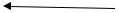
With the first connection, you should install the USB driver of the microcontroller onto the PC first. The location of this driver can be found on the included CD in the ‘USB_driver’ subfolder of the VM140 software.
Refer to the figures below illustrating the driver installation (example Windows XP):
VM140 is the builded version of K8061, software for K8061 is identical for VM140
Screenshots may vary with different operating system
Step 1 : New hardware detected
Local driver, don't run Windows Update
Step 2 : Select "specific location"
6
software installation
Step 3 : Browse through the driver folder on your hard disk or included CD.
Select driver : mchpusb.sys
Step 4 : Click "Continue Anyway"
Step 5 : Click "Finish"
7

software installation
Installation is successful
A utility to check the operation of the VM140 can be found in the “DIAG8061” subfolder.
A more elaborate test application can be found in the “DEMO8061” subfolder.
The source code of the test application can be found in the “DLL examples” subfolder.
Explanation concerning the communication DLL of the VM140 can be found in the “DOC” subfolder.
8
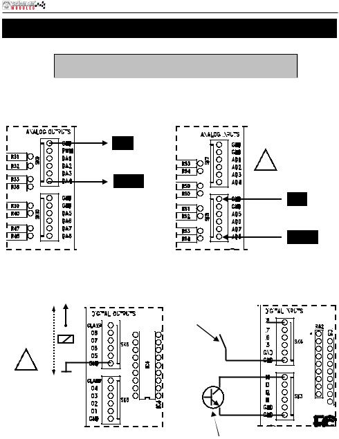
Connection example
How to connect :
Check the connections and respect limitations of the specifications to prevent damage.
1. Analog output : |
|
|
|
2. Analog input : |
|
|
|
||||||||||||||||||
|
|
|
|
|
|
|
|
|
|
|
|
|
|
|
|
|
|
|
|
|
|
|
|
|
|
GND |
ANALOG OUTPUT VOLTAGE |
! |
MAX 10V DC ! |
|
||
|
|
DAx : + |
GND |
0 till 5V |
OR |
0 ... 5V or 0 ... 10V |
|
|
0 till 10V |
ADx : + |
3. Digital output : |
|
|
|
|
|
|
|
|
|
|
|
|
|
|
|
|
|
|
|
|
4. Digital input : |
|
|
|
|
|
|
|
|
|
|
|
|
|
|
|
|
|
|
|
|
|
|
+V |
|
|
|
|
|
|
|
|
|
|
|
|
|
|
|
|
|
|
|
|
|||||||||||||||||||||
+V :External |
|
|
|
|
|
|
|
|
|
|
|
|
|
|
|
|
|
|
|
|
Switch, ... |
|
|
|
|
|
|
|
|
|
|
|
|
|
|
|
|
|
|
|
|
|
|
|
|
|
|
|
|
|
|
|
|
|
|
|
|
|
|
|
|
|
|
|
|
|
|
|
|
|
|
|
|
|
|
|
|
|
|
|
|
|
|||
power supply for |
|
|
|
|
|
|
|
|
|
|
|
|
|
|
|
|
|
|
|
|
|
|
|
|
|
|
|
|
|
|
|
|
|
|
|
|
|
|
|
|
|
|
relay, LED, |
|
|
|
|
|
|
|
|
|
|
|
|
|
|
|
|
|
|
|
|
|
|
|
|
|
|
|
|
|
|
|
|
|
|
|
|
|
|
|
|
|
|
Lamp. |
|
|
|
|
|
|
|
|
|
|
|
|
|
|
|
|
|
|
|
|
|
|
|
|
|
|
|
|
|
|
|
|
|
|
|
|
|
|
|
|
|
|
|
|
|
|
|
|
|
|
|
|
|
|
|
|
|
|
|
|
|
|
|
|
|
|
|
|
|
|
|
|
|
|
|
|
|
|
|
|
|
|
|
|
|
|
|
|
|
|
|
|
|
|
|
|
|
|
|
|
|
|
|
|
|
|
|
|
|
|
|
|
|
|
|
|
|
|
|
|
|
|
|
|
|
|
|
|
|
|
|
|
|
|
|
|
|
|
|
|
|
|
|
|
|
|
|
|
|
|
|
|
|
|
|
|
|
|
|
|
|
|
|
|
|
|
|
|
|
|
|
! |
OR |
MAX 50VDC |
GND |
|
External transistor "open collector" output
9

Eigenschappen en technische gegevens
Deze geassembleerde interfacekaart bestaat uit 33 ingangen / uitgangen, inclusief analoge / digitale en een PWM-uitgang.
De aansluiting naar de computer is galvanisch-optisch geïsoleerd om beschadiging te vermijden en zo de implementering te beveiligen.
Alle communicatieroutines zijn in een Dynamic Link Library (DLL) verzameld.
U kunt eigen Windows-toepassingen* schrijven in Delphi, Visual Basic, C++ Builder, Microsoft Visual Basic, Microsoft VC en de meeste 32-bit Windows-toepassingen die calls naar een DLL ondersteunen.
EIGENSCHAPPEN:
8 analoge ingangen met een resolutie van 10 bit: 0… 5 of 10VDC / 20k ohm
8 analoge ingangen met een resolutie van 8 bit: 0…5 V of 10VDC / 47 ohm
8 digitale ingangen: open collector compatibel (aansluiting met GND=0) met on-board indicatie-led
8 digitale opencollectoruitgangen (max. 50V/100mA) met on-board indicatie-led
een PWM-uitgang van 10 bit: 0 tot 100% opencollectoruitgang (max 100mA / 40V) met on-board indicatie-led
USB-poort: USB 1.1 & 2.0 compatibel
TECHNISCHE GEGEVENS:
∙verbruik langs een USB-poort: ongeveer 60mA
∙mogelijkheid om max. 8 kaarten met de pc aan te sluiten
∙voeding langs de adapter: 12VDC / 300mA (PS1205)
∙PWM-frequentie: 15.6kHz
∙standaard uitvoeringstijd: tussen 21 en 48ms
∙afmetingen PCB: 195 x 142 x 20mm
MINIMALE SYSTEEMVEREISTEN:
∙Pentium of hoger met vrije USB-poort (1.1 of hoger)
∙Microsoft Windows 2000 of Windows XP*
∙cd-romspeler en muis
*Windows XP is een geregistreerd handelsmerk van Microsoft Corporation.
*Windows XP is aanbevolen
10
11
19
12
3
8
4
 5
5
15
 6
6
16
 20
20
13
7
17
10
9
11
14
18
1
2
ansluitingen
Aansluitinge

aansluitingen
1
2
3
4
5
6
7
8
9
10
11
12
13
14
15
16
17
18
19
20
USB-connector |
Hier wordt de VM140 met de USB-poort van een pc verbonden. |
|
|
|
|
12VDC |
Aansluiting van de voeding. Hier sluit men een 12V ongestabiliseerde adapter op |
|
aan die minimaal 300mA kan leveren. |
||
|
||
|
|
|
Digitale ingangen |
|
|
1, 2, 3, 4 |
Om ze te activeren dient u deze extern “LAAG” te maken (verbinden met GND). |
|
|
||
Digitale ingangen |
||
|
||
5, 6, 7, 8 |
|
|
|
|
|
Digitale uitgangen |
Deze uitgangen zijn “open collector”-uitgangen, dit wil zeggen dat, als ze actief |
|
worden gemaakt, gaan de transistors in IC4 in “geleiding” en wordt er een |
||
1, 2, 3, 4 |
“verbinding” gemaakt tussen GND en de desbetreffende uitgang. De last die u |
|
|
wenst aan te sturen, zoals een LED, relais ..., moet dus een externe spanning |
|
Digitale uitgangen |
krijgen, de aansluiting “CLAMP” verbindt u eveneens met de + van deze externe |
|
5, 6, 7, 8 |
voeding. Dit dient om de transistor array te beschermen. |
|
Analoge ingangen |
Dit zijn meetpunten waarmee men een analoge spanning kan digitaliseren en |
|
uitlezen via de pc. De analoge ingangen verwachten een stabiele |
||
1, 2, 3, 4 |
||
gelijkspanning tussen 0 en 5V of tussen 0 en 10V. Deze selectie kan gemaakt |
||
|
||
|
worden met de jumpers AD1 tot AD8 (zie nr. 13). Opgelet: Een spanning |
|
Analoge ingangen |
||
aanleggen aan de A/D-ingangen groter dan 5 of 10V kan de VM140 |
||
5, 6, 7, 8 |
||
onherroepelijk beschadigen (IC10/11)! |
||
|
||
Analoge uitgangen |
Hier kan men softwarematig de gelijkspanning bepalen die u op deze |
|
uitgangen kan plaatsen. Afhankelijk van de stand van de jumpers DA1 tot DA8 |
||
1, 2, 3, 4 |
||
is deze spanning in te stellen tussen 0 en 5V of tussen 0 en 10V. Op pin 2 van |
||
|
||
Analoge uitgangen |
deze connector (SK9) vind u ook de PWM-uitgang. De PWM-uitgang is een |
|
5, 6, 7, 8 |
“open collector”-uitgang waarvan de pulsbreedte regelbaar is. |
|
|
|
|
Adressering |
Met de jumpers A1, A2 en A3 kunt u elke VM140 dat aangesloten is een uniek |
|
adres toekennen. Er kunnen max. 8 kaarten aangesloten worden. Als u |
||
selectiejumpers |
||
slechts één VM140 hebt, stel deze dan in op adres “0”. |
||
|
||
|
|
|
A/D maximale |
Met de jumpers AD1-AD8 kunt u het spanningsbereik voor de |
|
overeenkomstige A/D-ingangen selecteren tussen 0 tot 5V (gesloten) of 0 tot |
||
spanning |
||
10V (open). |
||
|
||
|
|
|
D/A maximale |
Met de jumpers DA1-DA8 kunt u het maximale spannings-bereik voor de |
|
overeenkomstige D/A-uitgangen selecteren tussen 0 tot 5V (open) of 0 tot 10V |
||
uitgangsspanning |
||
(gesloten) |
||
|
||
PWM controle-LED |
Deze LED licht op indien de PWM-uitgang actief is. De helderheid van deze |
|
LED is analoog aan de puls/pauze verhouding. |
||
|
||
|
|
|
CPU “run mode”- |
Licht op als de CPU van de VM140 (IC6) correct functioneert. |
|
LED |
||
|
||
|
Deze LED licht op als er data wordt uitgewisseld tussen de CPU en de USB |
|
CPU RC/TX-LED |
interface controller (IC3). Als deze LED niet oplicht tijdens de werking van de |
|
kaart, is er een fout in de USB controller (IC3) of in de optische scheiding (IC1 & 2) |
||
|
||
|
aanwezig. |
|
"POWER ON”-LED |
Licht op als de 5V voeding voor de USB-controller aanwezig is. Opgelet: Deze |
|
voeding wordt genomen uit de USB-poort van uw pc en is geen garantie voor |
||
|
de werking van het voedingsgedeelte van de VM140’s CPU en I/O-gedeelte. |
|
"USB”-LED |
Knippert tijdens USB-verbinding en licht constant op wanneer er een |
|
geslaagde communicatie tot stand gebracht is tussen de USB-chip in uw pc |
||
|
en de VM140. |
|
|
|
|
Aanduiding |
Deze LEDs doven als een overeenkomstige ingang “Laag” getrokken wordt |
|
(verbinding van ingang met GND) door een extern contact of externe “open |
||
digitale ingang |
||
collector”-uitgang. |
||
|
||
|
|
|
Aanduiding |
Deze LEDs lichten op als een overeenkomstige uitgang actief wordt, dit wil |
|
zeggen als er een verbinding ontstaat tussen een uitgangspin en GND (“open |
||
digitale uitgang |
||
collector”-uitgang). |
||
|
||
|
|
12
 Loading...