


 Push button & timer panel VMB4PD
Getting started manual / Beknopte handleiding / Instructions en bref / Ratgeber / Instrucciones breves
Optional:
VMBFDG |
VMBFLG |
VMBIRTS |
push button module with display ( 2 line 16 characters) all 8 commands (buttons) can have a custom label instant access of 4 commands, 4 commands on 2e page notification LED for each command
background LED illumination on the buttons on board Infrared remote control receiver power supply: 12V-18Vdc / 30mA
programmable clock / timer functions, 20 weekly or daily steps
clock can be set as master or slave, so that only 1 clock must be set to synchronise all your panels at once.
For extended manual see: www.velbus.be Voor een uitgebreide handleiding zie: www.velbus.be Pour la notice détaillée, voir : www.velbus.be
véase el amplio manual del usuario para más información: www.velbus.be siehe die ausführliche Bedienungsanleitung für mehr Information: www.velbus.be Per le istruzioni per l’uso dettagliati, vedasi : www.velbus.be

Connection example - Aansluitingsvoorbeeld - example de connexion -
Esquema de conexión - Schaltplan - Schema di collegamento
VMB4PD
L H
H
L BUS
+
- 12V
-12V+ BUS TWISTED
PAIR 2 Backside VMB4PD
(0.5mm )
 Velbus
12Vdc—18Vdc
2
ENGLISH
Thank you for choosing the Velbus system Push button and timer panel.
This versatile panel provides a lot of functions to facilitate the use of your Velbus automation system.
Direct control of output modules using 4 push buttons.
Additional 4 push buttons on second page, making a total of 8 push buttons. Possibility to provide each button from a custom label.
Possibility for timed actions on each button (day and week timer functions).
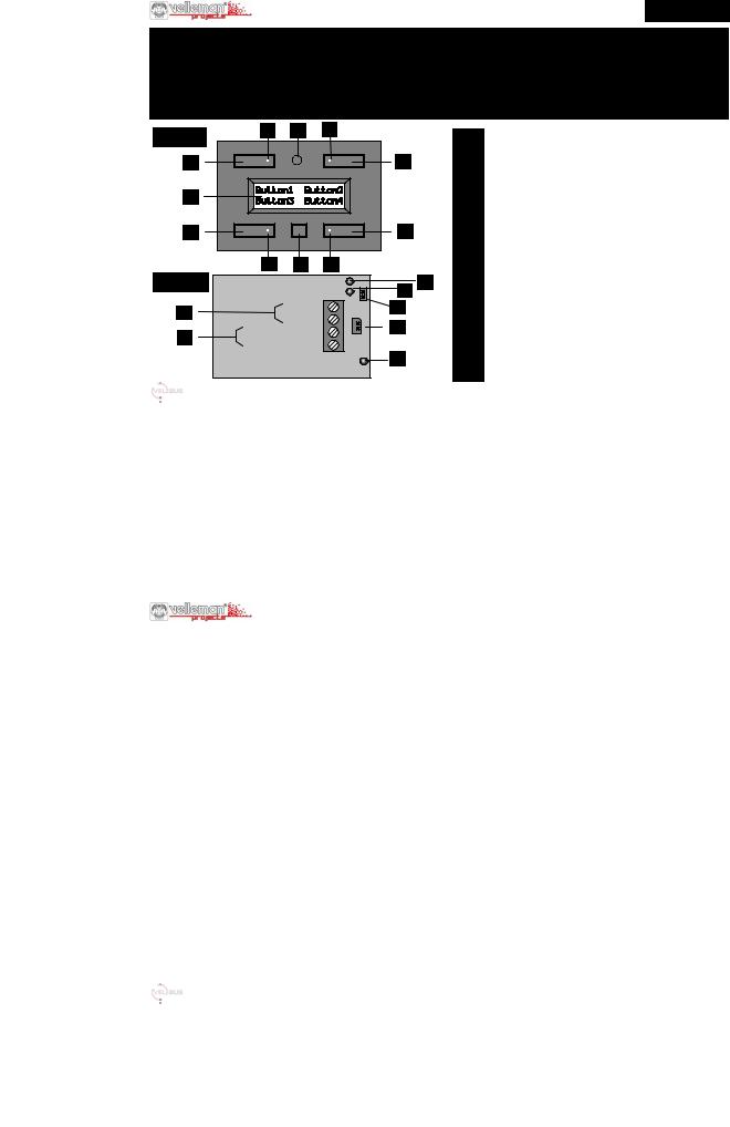
Front |
A |
I |
|
B |
|
|
1 |
Push button 1 (5) |
( ) = second page |
|
|
|
|
|
|
||||
1 |
|
|
|
|
2 |
|
2 |
Push button 2 (6) |
|
|
|
|
|
|
3 |
Push button 3 (7) |
|
||
|
|
|
|
|
|
|
4 |
Push button 4 (8) |
|
H |
|
|
|
|
|
|
5 |
Page selection / Configuration push button |
|
|
|
|
|
|
|
6 |
Termination |
|
|
|
|
|
|
|
|
|
7 |
Velbus (watch polarity) |
|
3 |
|
|
|
|
4 |
|
8 |
12Vdc - 18Vdc power supply |
|
|
|
|
|
|
|
|
9 |
9V Battery backup (for clock) |
|
|
|
5 |
|
|
|
|
A |
Backlight and indication LED push button 1 (5) |
|
|
|
|
|
|
|
B |
Backlight and indication LED push button 2 (6) |
||
Back |
|
|
|
|
|
F |
|||
|
|
|
|
E |
C |
Backlight and indication LED push button 3 (7) |
|||
|
|
|
H |
|
|
|
D |
Backlight and indication LED push button 4 (8) |
|
|
|
VelbusL |
+ |
9 |
|
E |
Velbus transmit LED |
|
|
|
12V Power supply |
+ |
- |
|
F |
Velbus reception LED |
|
||
|
- |
|
|
|
G |
Velbus power LED |
|
||
|
|
|
|
|
|
|
H |
2 line 16 charachters button labels (2 pages) |
|
|
|
|
|
|
|
|
I |
Infrared receiver for VMBIRTS |
|
3
ENGLISH
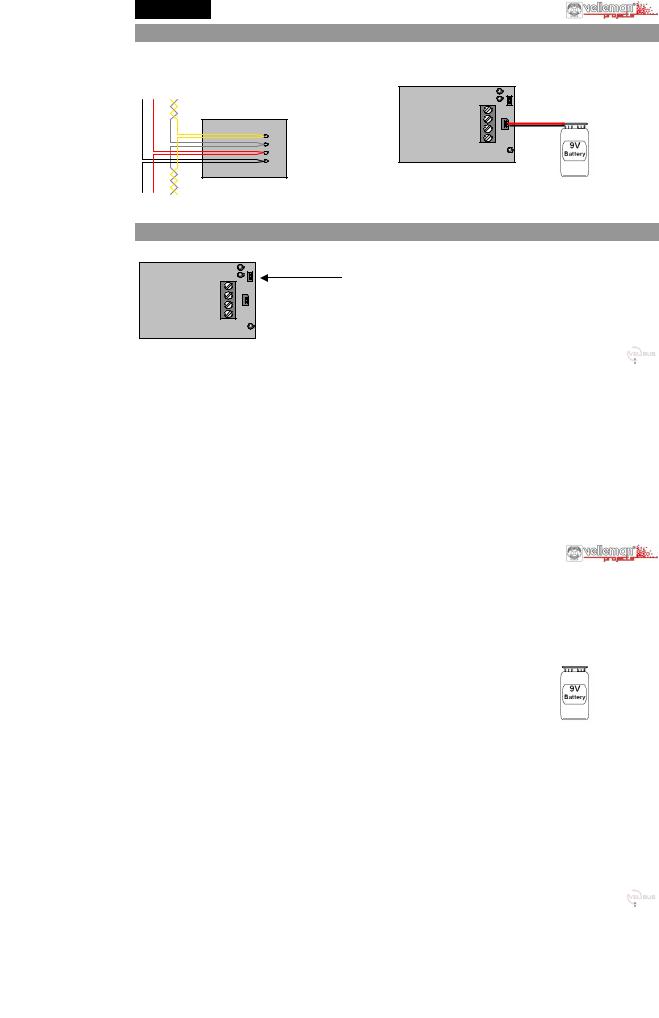
1. Connection
For connection between the modules, use twisted pair cable (ex. EIB 2x2x0.8mm2, UTP 8x0.51mm - CAT5 or other). For long wiring (>50m) or if a lot of modules ( > 10) are connected to one wire, use minimum 0.5mm² cable
Connect the 12-18Vdc (mind the polarity) and connect the bus wires (mind the polarity). See also the example on page 2.
|
VelbusH |
+ |
|
VMB4PD |
L |
|
|
+ |
- |
||
L H |
|||
12V Power supply - |
|||
H |
|
||
L BUS |
|
|
|
+ |
|
|
|
- 12V |
|
|
-12V+ BUS
TWISTED
PAIR (0.5mm 2)
If in case of a power failure you desire a backup for the internal clock: Connect a 9V battery (Use the included cable) .
This is only needed on 1 module (see also page 7).
2. Termination
|
|
If the module is connected at the start or end of a cable on the VELBUS, place the ‘TERM’ jumper. |
|
|
|
Remove the jumper in all other cases. |
|
VelbusH |
+ |
Terminator |
|
L |
|
|
|
+ |
- |
|
|
12V Power supply - |
If different cable wiring topologies (tree, star, loop, ...) are used, place a jumper on the end module of the |
||
|
|||
|
|
longest cable only (e.g. the last control module), NOT on each end point. |
|
|
|
Generally, only 2 termination jumpers will be used. |
4
ENGLISH
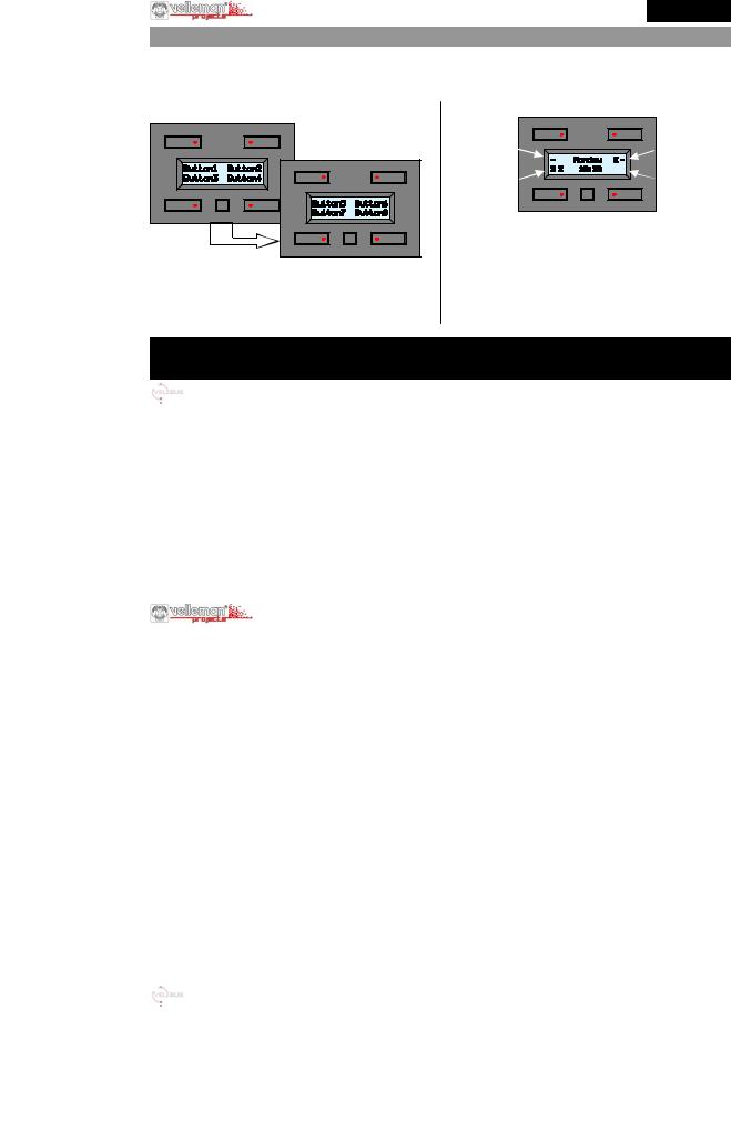
3. Buttons and display overview
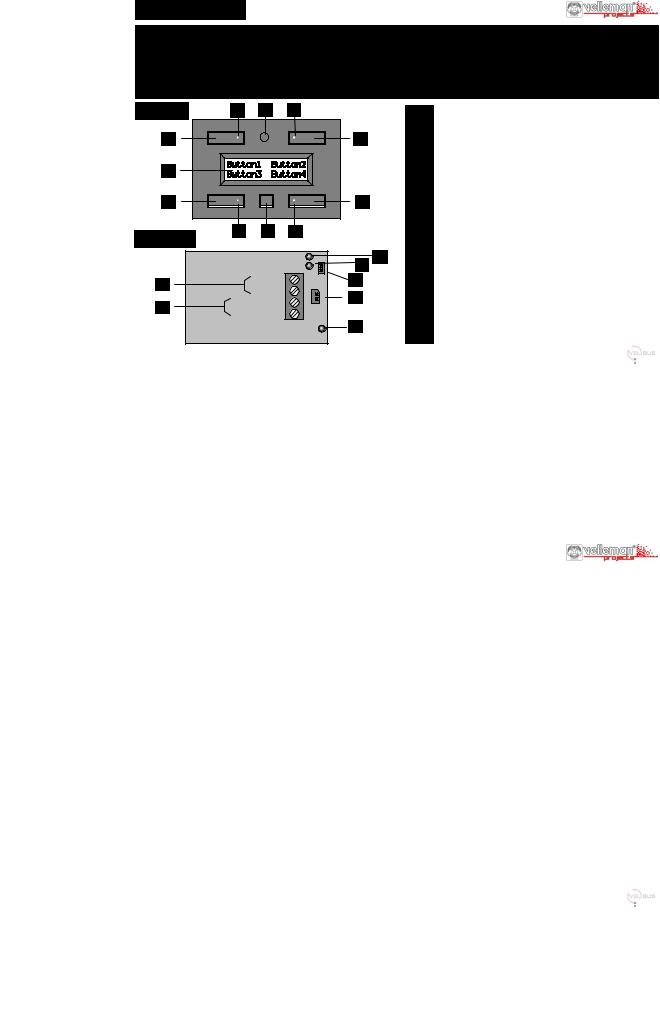
The module consists of 4 push buttons with corresponding LED indication and one configuration push button. The label for each push button is displayed on the LCD. Due to the use of 2 pages, up to 8 commands (buttons) are possible.
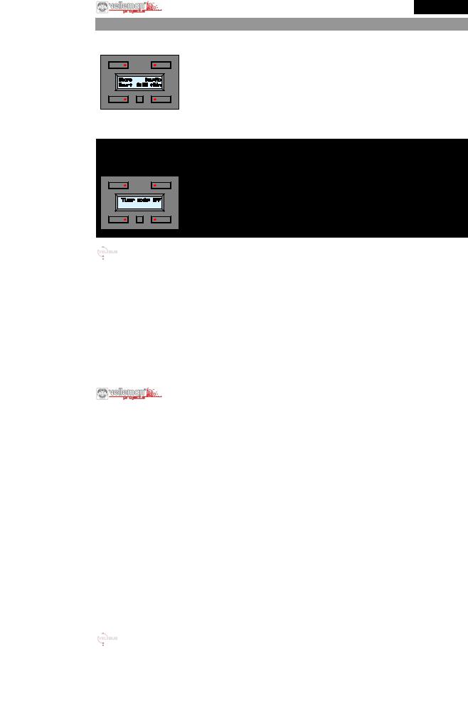
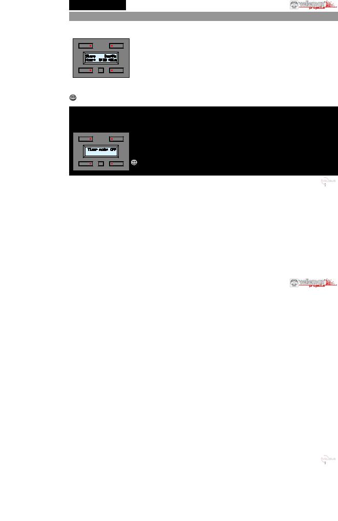
The module will display the first 4 commands by default ( Main page ).
MAIN PAGE
SECONDARY PAGE |
Next |
Switch between the displays at any time by pressing the small configuration button.
The module switches back to the main page after 15 seconds of inactivity (except when the time is displayed).
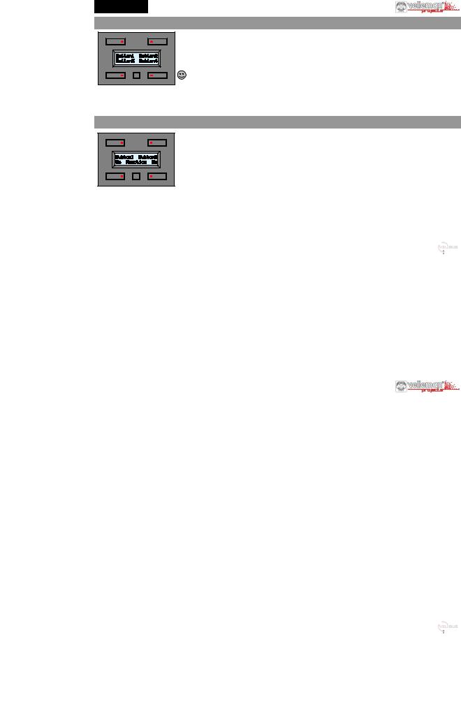
TIMER OVERVIEW PAGE
A |
C |
B |
D |
If the timer option is enabled (see page 7) then the timer can be displayed. On this panel we see:
A.Main page button has a timer, but the timer is disabled. The secondary page button has no timer function.
B.The buttons on main and secondary page have a timer and the timers are enabled.
C.The button on the main page has a timer and the timer is enabled,
the button on the second page has a timer but is disabled. D.The main and secondary page buttons have no timer functions.
How a specific push button will control a particular module is explained in the learning mode of the output modules.
The indication LED has two levels, the low level serves as button backlight, the high level indicates an action on this button. It is possible that the indication LED is incorrect, if more than 1 output function is programmed to the same button.
5
ENGLISH |
|
4. Setting the unique address for the module |
|
Every module connected onto the Velbus system must have a unique address which can be set via the configuration menu. |
|
This is important for the module identification in the system and for the IR transmitter. |
|
MAKE NOTE OF THE ADDRESS OF EACH MODULE IN YOUR SYSTEM |
|
1. |
Go to the second configuration menu (long press the small button, then press again) |
2. |
Press the upper right “Address” button to display the address menu. ( after 30 seconds of inactivity, the module exits' the menu) |
The upper buttons left or right button to select the address digit (blinking digit).
Keep the lower left button pressed, press the lower right button to modify the selected address digit. Select an address between “00” and “FE”. (00= lowest address, FE = highest address )
The small configuration button to quit the address menu.
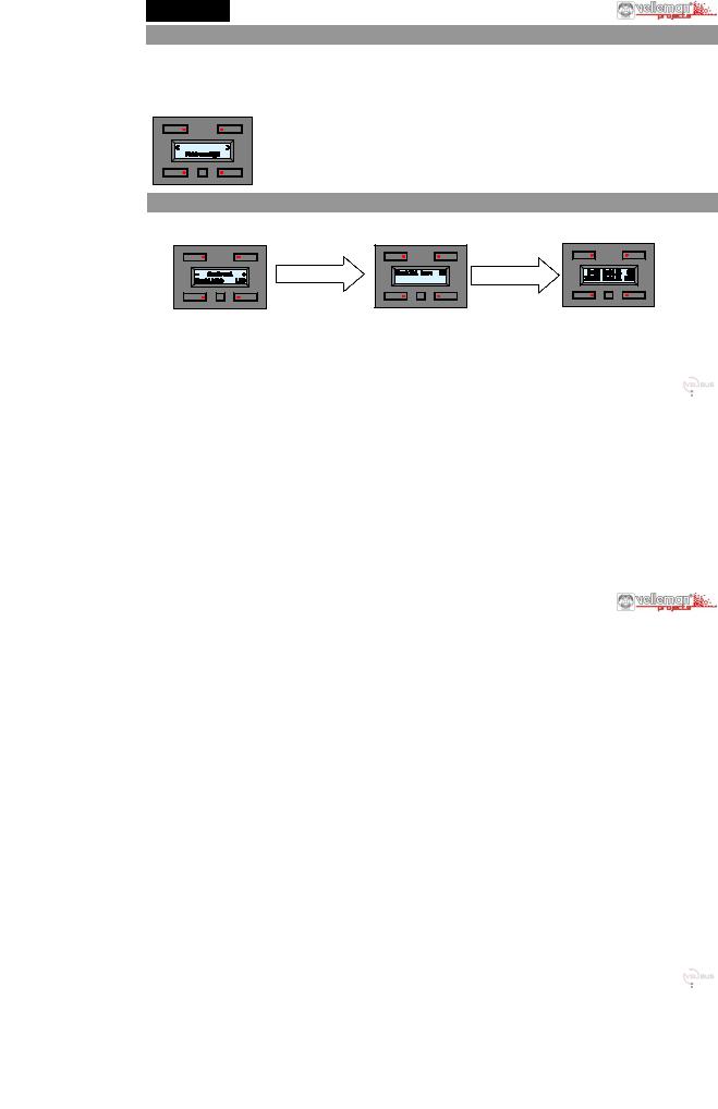
5. Setting the LCD and button backlight features
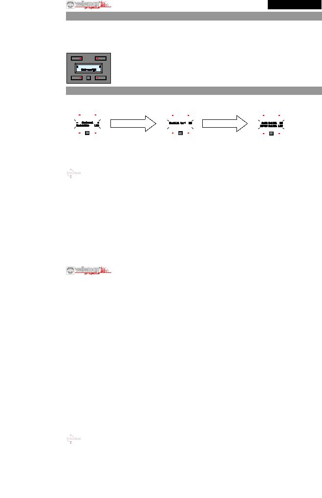
1. Go to the first configuration menu (long press the small button)
2. Press the upper right “Display” button ( after 30 seconds of inactivity, the module exits' the menu)
|
|
Press small |
|
Press small button |
Press small button |
button to |
|
EXIT |
|||
|
|
Adjust the contrast using + and - Press backlight button to change the backlight intensity manually.
Press LED button to change the button LED backlight intensity
Select if the backlight must dim automatically (ON) or not (OFF), useful if panel is used in the bedroom .
Next you can set a time for the dimming period.
Using the 4 buttons, select the backlight time and corresponding:
ON / OFF / LOW / MID setting. Note: the selected action will only execute after the set time is crossed.
6
ENGLISH
6. Setting the Clock (this must be done for at least one clock in your system)
1. |
Go to the first configuration menu (long press the small button) |
|
2. |
Press the upper left “Clock” button ( |
after 30 seconds of inactivity, the module exits' the menu) |
The “Hour” button to set the hour The “Min” button to set the minutes
The “Day” button to select the day of the week:
Mo= Monday; Tu= Tuesday; We= Wednesday; Th= Thursday; Fr= Friday; Sa= Saturday; Su= Sunday The “Store” button to validate your settings and to start the seconds, it will also update all the clocks in your system (*) The module switches back to the main page after 2 min. of inactivity .
(*) If you press the small button, the clock will NOT be set and you will be able to set the clock as master (ON) or slave (OFF).  Set one clock set as master, this clock will update all the clocks in your system once a day.
IMPORTANT: If you want to display the clock, then the timer function of the panel must be enabled (See also page 5)
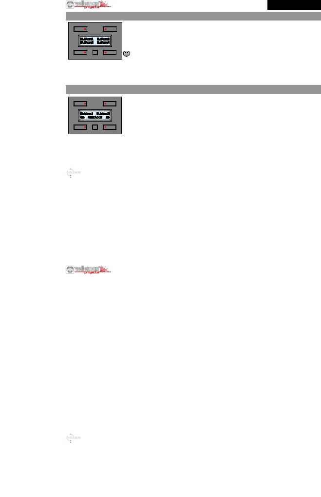
1.Go to the second configuration menu (long press the small button, then press again)
2.Press the upper left “Mode” button to display the mode menu.
The upper right button to select the panel operation mode:
OFF: No timer functions are available ( default factory setting ).
4CH: Timer functions can be set on the 4 buttons from the second page only (buttons 5 to 8). 8CH: Timer functions can be set on the 4 buttons of the two pages.
 If you want to turn all timers OFF at once (e.g. during vacation period), you could use the OFF setting).
7
ENGLISH
7. Editing the button labels (can also be done using a PC and the Velbuslink software)
1. Go to the second configuration menu (long press the small button, then press again) 2. Press the lower right “Labels” button to start the editing page (blinking digit).
Use the upper buttons to select a position, use the lower buttons to select a character.
Keep one of the lower buttons pressed to quickly scroll to a character, the scrolling will always stop at a “space”.
The small button to go to the next label page, press again to exit.
8. Set the reaction time of each button (can also be done using a PC and the Velbuslink software)
To prevent accidental button action, it is possible to set a reaction time on each of the eight buttons (4 on first page and 4 on second page). Default the reaction time is set as direct (0s).
1. Go to the second configuration menu (long press the small button, then press again) 2. Press the lower left “Reaction” button to display the reaction set-up menu .
Press the lower buttons to change the reaction time of the above displayed buttons, each press will select: 0s (direct), 1 second, 2 seconds, 3 seconds reaction time.
The small button to go to the next label pages, press again to exit.
8

ENGLISH
9. Timer programming (can also be done using a PC and the Velbuslink software)
Each button can be “automatically” pressed using timed instructions. By default this mode is OFF, see page 7.
If timer functions will be used, do not use toggle buttons, use separate ON and OFF buttons. Consider that combinations can be made using the timer functions of e.g. a relay module ( Start timer / Stop timer / Staircase..). Download the extended manual for more info.
1 |
Go to the first configuration menu (long press the small button)
Press the lower left “Prog” button to enter the program menu
Select the step you want to use or edit using Up ▲ or Down ▼ buttons (max 20 steps can be set)
1.Press Enter (lower left button)
2.Using the upper right button select if this timed action bust be performed: Never= No action; Mo= Monday; Tu= Tuesday; We= Wednesday; Th= Thursday;
Fr= Friday; Sa= Saturday; Su= Sunday; Sa&Su= Saturday and Sunday; Mo-Fr= Monday to Friday; Mo-Sa= Monday to Saturday; Mo-Su= Every day.
3.Using the lower buttons select the moment (Hour and Minutes) this step must be executed.
4.Press the small configuration button, then select which button must be assigned to this step. A indicates if the timer function is assigned. Repeat step 5 for each of the buttons until screen 1(re)appears.
5.Add program steps if needed by repeating steps 1 to 5 or press the small button to exit.
NOTE: After timer steps have been entered, the timer(s) can be enabled or disabled for each programmed button (see also page 5 ). This is a handy function to disable (or enable) some timed buttons during a vacation period.
Go to the first configuration menu (long press the small button).
Press the lower right “on/off” button.
Each press on the small button will select a “button” page until exit.
Use the lower buttons to enable or disable a timed button.
= Enabled − = Disabled _= Notimer
9
NEDERLANDS
Bedankt voor de aankoop en het gebruik van het VELBUS bedieningspaneel. Met dit bedieningspaneel met zijn vele mogelijkheden vereenvoudigt u het gebruik van uw VELBUS domoticasysteem.
Bediening van uitgangsmodules door middel van 4 drukknoppen Tot 8 bedieningen mogelijk (2 sets van 4 bedieningen)
Aan iedere bediening kan een label op het scherm toegekend worden
Programmeerbare schakelfuncties om drukknopacties te automatiseren (dagof weekprogramma’s).
Voorzijde |
A |
I |
B |
|
|
1 |
Drukknop 1 (5) |
( )= 2de pagina |
|
|
|
|
|
|
2 |
Drukknop 2 (6) |
|
1 |
|
|
|
2 |
|
3 |
Drukknop 3 (7) |
|
|
|
|
|
|
|
4 |
Drukknop 4 (8) |
|
H |
|
|
|
|
|
5 |
Paginakeuze / configuratiedrukknop |
|
|
|
|
|
|
6 |
Afsluiting |
|
|
|
|
|
|
|
|
7 |
Velbus |
|
3 |
|
|
|
4 |
|
8 |
Voeding 12 tot 18Vdc |
|
|
|
|
|
9 |
Back-upbatterij 9V (voor de klok) |
|
||
|
|
|
|
|
|
|
||
|
|
5 |
|
|
|
A |
Toetsverlichting en indicatieled bediening 1 (5) |
|
Achterzijde |
|
|
|
|
B |
Toetsverlichting en indicatieled bediening 2 (6) |
||
|
|
|
|
|
C |
Toetsverlichting en indicatieled bediening 3 (7) |
||
|
|
|
|
|
F |
|||
|
|
|
|
E |
D |
Toetsverlichting en indicatieled bediening 4 (8) |
||
|
|
H |
|
|
|
E |
Velbus zendled |
|
|
|
VelbusL |
+ |
9 |
|
F |
Velbus ontvangstled |
|
|
|
+ |
- |
|
G |
Velbus voedingsled |
|
|
|
12V voeding - |
|
|
H |
toetslabels (2 regels van elk 16 karakters, 2 pagina’s) |
|||
|
|
|
|
|||||
|
|
|
|
|
|
I |
Infrarood ontvanger voor afstandsbediening |
|
|
|
|
|
|
|
VMBIRTS |
|
|
|
|
|
|
|
|
|
|
|
10
NEDERLANDS
1. Aansluiting
Om de modules met elkaar te verbinden gebruikt men best een twisted-pair kabel (EIB 2x2x0.8mm2, UTP 8x0.51mm - CAT5 of gelijkwaardig). Indien er veel modules (meer dan 10) op de kabel aangesloten of bij zeer lange leidingen (langer dan 50m) is het belangrijk om de draaddoorsnede voldoende dik te voorzien (0.5mm2 of meer). Verbind de 12 tot 18V gelijkspanning (let op de polariteit) met de module. Sluit de bus aan (let op de polariteit) op de module. (Zie ook aansluitschema pag. 2)
VMB4PD
L H
H
L BUS
+
- 12V
-12V+ BUS
TWISTED
PAIR (0.5mm2)
2. Afsluiting
VelbusH |
+ |
|
L |
|
|
+ |
- |
|
12V voeding- |
||
|
Sluit een 9 Volt batterij aan (via het meegeleverde kabeltje) indien de klok verder moet lopen tijdens een spanningsonderbreking.
Dit moet maar op één module gebeuren (zie ook blz. 14)
Monteer een afsluitjumper 'TERM' op het verste bedieningspaneel in de woning. In alle andere gevallen moet deze verwijderd worden.
VelbusHL 12V voeding+-
+
-

 Afsluiting
Opmerking: Indien de bekabeling in sterof boomstructuur uitgevoerd is, wordt er enkel een afsluiter geplaatst op de module die aan het beginpunt (bv. in de verdeelkast) van de kabel aangesloten is en op de module die op het uiteinde (bv. verste bedieningspaneel in de woning) van de langste kabel aangesloten is. In de meeste klassieke woningen zullen er slechts 2 afsluitjumpers gebruikt moeten worden.
11

NEDERLANDS
3. Bedieningen schermoverzicht
De module bevat vier drukknoppen met bijhorende indicatieleds en een configuratiedrukknop. Op het scherm wordt een label getoond voor elke drukknop. Door gebruik te maken van 2 pagina’s kunnen tot acht bedieningen verwezenlijkt worden.
Standaard stelt de module zich in op de eerste vier bedieningen (hoofdpagina).
HOOFDPAGINA |
SECUNDAIRE |
PAGINA |
volgende |
Er kan op elk ogenblik tussen beide pagina’s geschakeld worden door de kleine configuratiedrukknop te bedienen. Wordt er gedurende 15 seconden geen enkele drukknop bediend, dan keert de module terug naar de hoofdpagina (tenzij de tijd getoond wordt).
OVERZICHT SCHAKELKLOK
A |
C |
B |
D |
Indien de schakelklok geactiveerd is (zie pag. 14), kan de klok getoond worden. Verklaring symboliek:
A.De drukknop van de hoofdpagina wordt in het programma gebruikt maar het klokprogramma wordt niet uitgevoerd. De drukknop van de secundaire pagina wordt in het schakelprogramma niet gebruikt.
B.De drukknoppen van de standaard en de secundaire pagina worden in het programma gebruikt en het programma zal uitgevoerd worden.
C.De drukknop van de hoofdpagina wordt in het programma gebruikt en het klokprogramma zal uitgevoerd worden. De drukknop van de secundaire pagina wordt in het programma gebruikt maar het klokprogramma wordt niet uitgevoerd.
D.De drukknoppen van de hoofd en de secundaire pagina worden niet in het klokprogramma gebruikt.
In de leermodus van de uitgangsmodules staat hoe een specifieke drukknop die module bedient. De indicatieled kan 2 lichtsterktes aannemen. De laagste dient voor de toetsverlichting en de hoogste geeft de toestand van de bediende module(s) aan. Wordt met een enkele drukknop meerdere modules bediend, dan bestaat de mogelijkheid dat de toestand ervan niet volledig correct weergegeven wordt op de indicatieled.
12
NEDERLANDS
4. Instellen van het unieke adres
Iedere module aangesloten op het Velbus-systeem moet een uniek adres bezitten dat via het configuratiemenu ingesteld kan worden. Dit is belangrijk om de module te kunnen identificeren in het Velbus-systeem en voor de infraroodzender.
NOTEER HET ADRES VAN IEDERE MODULE IN UW VELBUS-SYSTEEM
1.Roep het tweede configuratiemenu op (de kleine drukknop lang indrukken en opnieuw indrukken).
2.Bedien de drukknop rechtsboven om het adresmenu op te roepen (na 30seconden van geen bediening wordt het menu automatisch verlaten).
Met de 2 bovenste drukknoppen wordt de linkerof rechteradresdigit geselecteerd (zie knipperende digit).
Houd de drukknop linksonder ingedrukt terwijl de drukknop rechtsonder bediend wordt om de geselecteerde adresdigit te wijzigen. Op deze wijze kan een adres tussen ‘00’ (laagste adres) en ‘FE’ (hoogste adres) toegekend worden aan de module.
Bedien de kleine drukknop om het menu te verlaten.
5.Scherminstellingen en achtergrondverlichting
1.Roep het configuratiemenu op (lang indrukken van de kleine drukknop).
2.Bedien de drukknop rechtsboven om het schermmenu op te roepen. (na 30seconden van geen bediening wordt het menu automatisch verlaten).
|
|
|
|
|
|
|
|
|
|
Bedien de kleine drukknop |
|
|
|
|
|
|
|
|
|
|
Bedien de kleine drukknop |
|
|
|
|
|
|
|
|
|
Bedien de kleine |
|
|
|
|
|
|
|
|
|
|
|
|
|
|
|
|
|
|
|
|
|
|
|
|
|
|
|
|
|
|||
|
|
|
|
|
|
|
|
|
|
|
|
|
|
|
|
|
|
|
|
|
|
|
|
|
|
|
|
|
|||
|
|
|
|
|
|
|
|
|
|
|
|
|
|
|
|
|
|
|
|
|
|
|
|
|
|
|
|
|
|||
|
|
|
|
|
|
|
|
|
|
|
|
|
|
|
|
|
|
|
|
|
|
|
|
|
|
|
|
|
drukknop om het |
||
|
|
|
|
|
|
|
|
|
|
|
|
|
|
|
|
|
|
|
|
|
|
|
|
|
|
|
|
|
|
|
menu te verlaten. |
|
|
|
|
|
|
|
|
|
|
|
|
|
|
|
|
|
|
|
|
|
|
|
|
|
|
|
|
|
|
|
|
|
|
|
|
|
|
|
|
|
|
|
|
|
|
|
|
|
|
|
|
|
|
|
|
|
|
|
|
|
|
|
|
|
|
|
|
|
|
|
|
|
|
|
|
|
|
|
|
|
|
|
|
|
|
|
|
|
|
|
|
|
|
|
|
Stel het contrast in met de drukknoppen + of -. Wijzig de achtergrondverlicht van het scherm met de drukknop ‘Backlight’.
Wijzig de toetsverlichting met de drukknop ‘LED’.
Met de drukknop rechtsboven kan de achtergrondverlichting dagelijks automatisch gedimd worden (bv. bij gebruik in een slaapkamer). Daarna worden de twee tijdstippen gedefinieerd.
Met de 4 drukknoppen worden de tijdstippen met de bijbehorende lichtsterktes (OFF – LOWMID - ON) ingesteld.
Noot: de ingestelde lichtsterkte wordt pas aangenomen als de tijd het geprogrammeerde tijdstip bereikt.
13
NEDERLANDS
6. Instellen van de klok (dit hoeft maar op één module van uw Velbus-systeem)
1.Roep het configuratiemenu op (lang indrukken van de kleine drukknop).
2.Bedien de drukknop linksboven om het klokmenu op te roepen. (na 30seconden van geen bediening wordt het menu automatisch verlaten)
Stel het uur in met de drukknoppen ‘Hour’ en ‘Min’.
Bedien de drukknop ‘Day’ om de dag van de week in te stellen (Mo = maandag; Tu = dinsdag; We = woensdag; Th = donderdag; Fr = vrijdag; Sa = zaterdag; Su = zondag).
Wacht de minuutovergang af en druk op ‘Store’, de ingestelde tijd wordt dan geactiveerd op alle klokken die op het Velbus-systeem aangesloten zijn. Het klokmenu wordt verlaten (wordt er echter gedurende 2 minuten geen enkele drukknop bediend, dan wordt het klokmenu automatisch verlaten).
(*) Wordt er in plaats van de drukknop ‘Store’ de kleine drukknop bediend, dan zal de tijd niet ingesteld worden maar komt men in het instelmenu voor de hoofdklok (Master clock).
Er hoeft maar één hoofdklok ingeschakeld te zijn op van uw Velbus-systeem. Deze zal dagelijks alle andere klokken van het Velbussysteem gelijkstellen.
BELANGRIJK: Als u de tijd op het scherm wilt weergeven, moet de schakelklokfunctie geactiveerd zijn (zie pag.12).
1.Roep het tweede configuratiemenu op (lang indrukken van de kleine drukknop en opnieuw drukken).
2.Bedien de drukknop linksboven om het mode menu op te roepen.
14 |
Bedien de drukknop rechtsboven om de gebruiksmodus in te stellen. ‘OFF’: enkel bedieningspaneel (geen schakelklokfuncties)
‘4CH’: bedieningspaneel met schakelklokfuncties op de 2e pagina (bedieningen 5 ~ 8) ‘8CH’: bedieningspaneel met schakelklokfunctie op alle bedieningen
TIP: u kunt alle schakelprogramma’s simultaan uitschakelen (bv. tijdens vakantie) door voor de modus ‘OFF’ te kiezen.
NEDERLANDS
7. Wijzigen van de labels (kan ook via het Velbuslink-programma op een pc)
1. Roep het tweede configuratiemenu op (lang indrukken van de kleine drukknop en opnieuw drukken). 2. Bedien de drukknop rechtsonder om de labels te wijzigen.
Gebruik de bovenste drukknoppen om de cursor te verplaatsen en de onderste om het karakter op de cursorpositie te wijzigen.
TIP: Ingedrukt houden van een van de onderste drukknoppen start het scrollen. Bij het scrollen doorheen de karakterset wordt er automatisch gestopt bij een spatie.
Druk op de kleine drukknop om naar de tweede pagina met bijbehorende labels over te schakelen, druk opnieuw om het menu te verlaten.
8. Instellen van de reactietijd (kan ook via het Velbuslink-programma op een pc)
Om niet toevallig een bediening te activeren kan men er een reactietijd van 1, 2 of 3 seconden aan toekennen. Standaard staat deze ingesteld zonder vertraging (0s).
1. Roep het tweede configuratiemenu op (lang indrukken van de kleine drukknop en opnieuw drukken). 2. Bedien de drukknop linksonder om de reactietijd te wijzigen.
Bedien de drukknoppen linksof rechtsonder om een reactietijd van 0, 1, 2 of 3 seconden in te stellen voor de bediening waarvan het label getoond wordt.
Druk op de kleine drukknop om naar de volgende labels te gaan of om het menu te verlaten.
15
 Loading...