Velleman DVM831 User Manual [en, de, es, fr]
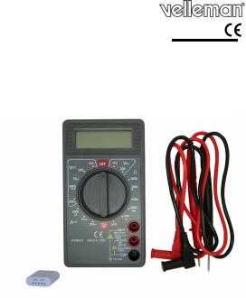
DVM831
3 1/2 DIGITS DMM
3 1/2-DIGIT DMM
MULTIMÈTR E NUMÉRIQUE 3 ½ DIGITS MULTÍMETR O 3 ½ DÍGITOS
3 ½-STELLI GES MULTIMETER
USER MANUAL |
3 |
GEBRUIKER SHANDLEIDING |
13 |
NOTICE D’E MPLOI |
24 |
MANUAL DEL USUARIO |
35 |
BEDIENUNGSANLEITUNG |
45 |

DVM831
1 |
DISPLAY |
|
1 |
DISPLAY |
2 |
FUNCTION AND RANGE |
|
2 |
FUNCTIEen |
|
SWITCH |
|
|
BEREIKSCHAKELAAR |
3 |
"10A" JACK |
|
3 |
"10A" AANSLUITING |
4 |
"VΩmA" JACK |
|
4 |
"VΩmA" AANSLUITING |
5 |
"Common" JACK |
|
5 |
"10A" AANSLUITING |
|
|
|
|
|
1 |
AFFICHEUR |
|
1 |
PANTALLA |
2 |
SÉLECTEUR de FONCTION et de |
|
2 |
SELECTOR de FUNCIÓN y de |
|
PLAGE |
|
|
RANGO |
3 |
CONNEXION "10A" |
|
3 |
CONEXIÓN "10A" |
4 |
CONNEXION |
|
4 |
CONEXIÓN "VΩmA" |
5 |
Common |
|
5 |
CONEXIÓN "Common |
1DISPLAY
2FUNKTIONSund BEREICHSSCHALTER
310A-BUCHSE
4VΩmA-BUCHSE
5Common-BUCHSE
31.03.2010 |
2 |
©Velleman nv |
DVM831
USER MANUAL
1. Introduc tion
To all residen ts of the European Union
Im portant environmental information about th is product
Thi s symbol on the device or the package indicates that disposal of the device after its lifecycle could harm the en vironment. Do not dis pose of the unit (or b atteries) as unsorted municipal waste; it should be taken to a specialized company for recycling. This device should be returned to your distributor or to a local recycling service. Respect the local environ mental rules.
If in doubt, contact your local waste disposal authorities.
Please read th e manual thoroughly before bringing this device into service. If the device was damaged in transit, do not use it and c ontact your dealer.
Damage caused by disregard of certain guidelines in this manual is not covere d by the warranty and the dealer will not accept responsibility for any ensuing defects or prob lems.
The DVM831 is a CAT II - 500V digital multi meter with a 3 ½ digit LCD; this device is suita ble for measuring dire ct and alternating voltages and currents, resistance, con tinuity, diodes and transistors.
Be extremly ca utious when using this device: carelessnes s can lead to serious or even fatal injuries. Apart from the usual safety precautio ns applicable when working with circuits the user must comply to the safety precautions as mentioned in this manual. Do not use this device when y ou are unfamiliar with circuits or test procedures!
This device is not suitable for commercial or industrial use.
Refer to the V elleman® Service and Quality Warranty on the last pages of this manual.
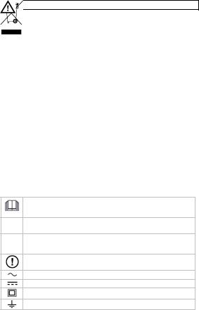
2. Used sy mbols
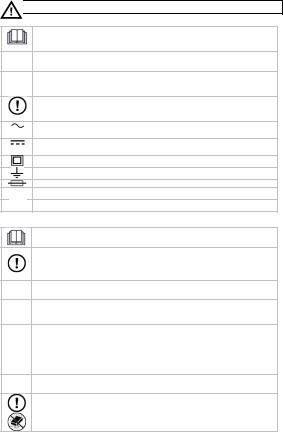
This symbol indicates: R ead instructions
Not reading the instruction s and manual can lea d to damage, injury or death .
This symbol indicates: D anger
A haz ardous condition or action that may result in injury or death
This symbol indicates: R isk of danger/damage
Risk of a hazardous condition or action that ma y result in damage, injur y or death
This symbol indicates: A ttention; important information
Ignoring this information can lead to hazardous situations.
AC (A lternating Current)
DC ( Direct Current)
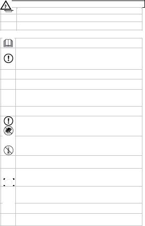
Double insulation (class II -protection)
Earth
31.03.2010 |
3 |
©Velleman nv |
DVM831
Fuse
Diode
Continuity
3. Warnings and safety instructions
Read this manual thorough ly. Familiarise yourse lf with the functions of the device before actually using it.
Only use the device for its intended purpose. Us ing the device in an unauthorized way will void the warranty. Dama ge caused by disregard of ce rtain guidelines in this manual is not cover ed by the warranty an d the dealer will not accept responsibility for any ensuing defects or problems.
Follow the instructions below to guarantee a saf e use of the meter and all its functionalities.
Durin g use of the meter, re spect all directives co ncerning protection again st electroshocks and misuse. Never exceed the indicated limits.
WAR NING:
To avoid electrical shock remove test leads befo re opening the device To pr event fire, only install fuses with AMP/VOLT rating shown. Rema rk: refer to the warning on the back of th e meter.
Keep the device away from children and unauth orised users.
Protec t this device from sh ocks and abuse. Avoi d brute force when operating.
Avoid cold, heat and large temperature fluctuati ons. When the unit is moved from a cold to a warm location, leave it switched off until it has reached room temperature. This to avoid conden sation and measurin g errors.
This is an installation category CAT II 500V measuring instr ument. Never use this equipment in a higher category than indicated. Refer to §4 Overvoltage /installati on category.
Pollution degree 2-device. For indoor use only. K eep this device away from rain, moisture, splashing and dripping liquids. Not for industrial use. R efer to §5 Pollutio n degree.
Before each use, make sure the test probes are in good condition. Alwa ys place your fingers behind the protective edges of the test
probe s while measuring! N ever touch free terminals when the meter is conn ected to a circuit.
Make sure the meter is in the appropriate measuring range before conn ecting it to a test circ uit.
Risk of electric shock during operation. Be v ery careful when meas uring live circuits. Use extreme caution wh en measuring voltages higher than 60Vdc or 30Vac rms.
31.03.2010 |
4 |
©Velleman nv |
DVM831
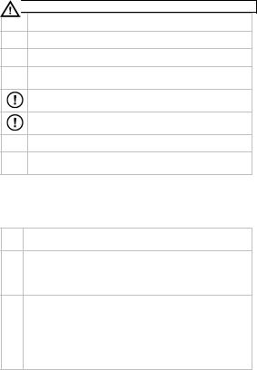
Do n ot measure circuits that may contain voltag es > 500V
Do n ot measure current in circuits with voltages > 250V
Do n ot conduct resistance, diodeor continuity measurements on live circuits.
When measuring currents meas urement followed by meas urements.
up to 10A, max. 10s continuous a 15 minutes break b etween 2
When carrying out measur ements on a TV set or switching power circuit s, always be aware t hat high amplitude voltage pulses at the test points might damage the m eter.
Do not replace internal parts yourself. Replace damaged or lost
acces sories by identical ones with the same specifications. Order spare acces sories e.g. test probes at your dealer.
Switch off the meter and remove test probes prior to replacing the battery or fuses.
All modifications of the de vice are forbidden for safety reasons.
Dam age caused by user modifications to the device is not covered by the w arranty.
4. Overvolt age/installation category
DMMs are categorized depending on the risk and severity of transient overvoltage that might occur at the point of test. Transients are short-lived bursts of energ y induced in a syste m, e.g. caused by lightning strike on a power line.
The existing ca tegories according E N 61010-1 are:
A CAT I-rated meter is suitab le for measurements on protected electron ic CAT I circuits which are not directl y connected to mains power, e.g. electronic s
circuits , control signals…
A CAT II-rated meter is suitable for measurement s in CAT I- environments and mono-phase appliances which a re connected to the
CAT mains b y means of a plug and circuits in a normal domestic environme nt,
IIprovided that the circuit is at least 10m apart from a CAT IIIor 20m apart from a CAT IV-environ ment. E.g. household appliances, portable tools…
|
A CAT III-rated meter is suitable for measuremen ts in CAT I- and CAT I I- |
|
CAT |
environments, as well as for measurements on (fi xed) monoor poly- |
|
phased appliances which are at least 10m apart from of a CAT IV- |
||
III |
environment, and for measu rements in or on distribution level equipment |
|
|
||
|
(fuse b oxes, lighting circuits, electric ovens). |
|
|
A CAT IV-rated meter is suit able for measuring in CAT I-, CAT IIand |
|
CAT |
CAT III -environments as well as on the primary su pply level. |
|
IV |
Note that for all measureme nts on equipment for which the supply cables |
|
run outdoors (either overhead or underground) a CAT IV meter must be |
||
|
||
|
used. |
Warning:
This device was designed in accordance with EN 61010-1 installation category CAT II 500V. This implies that certain restrictions in use apply that are related
31.03.2010 |
5 |
©Velleman nv |
DVM831
to voltages an d voltage peaks which can occur within the environment of use. Refer to the table above.
This device is suitable for measu rements up to 500V on:
• Protected electronic circuits whic h are not directly con nected to mains power, e.g. electro nics circuits, control signals, circuits behind isolating transforme r…
• circuits whic h are directly connected to mains power, but limited to:
• measure ments on mono-phas e appliances which are connected to the mains by means of a plug
• mono-phase appliances and circuits directly connected to the mains in a normal domestic environment , provided that the circuit is at least 10m apart from a CAT IIIor 20m apart from a CAT IV-e nvironment. E.g. household appliances, portabl e tools, light circuits at more than 10m fro m a distribu tion board …
This device is NOT suitable for:
•Voltages above 500V
•measurements in/on low-voltage distribution boards ( distribution boards behind met er box)
•measurements on (fixed) monoor poly-phased applia nces and circuits in
CAT III or CAT IV environments ( e.g. mains outlets, electric ovens, lighting circuits, bus bars, low-voltage dis tribution boards and circuit breakers).
•Measureme nts on distribution eq uipment and outdoor installations including meter boxe s and equipment/circ uits outside or remote from the domestic environment e.g. circuits in sheds, garden houses and free-standing garages, or circuits using underground wiring e.g. garden lighti ng, pool-pump...
This device is only suitab le for measurements up to 500V in CAT II env ironments.
5. Pollutio n degree
IEC 61010-1 specifies different types of pollution environments, for which different protective measures are ne cessary to ensure safety. Harsher environments require more protecti on, and the protection against the pollution which is to be found in a certain env ironment depends mainly on the insulation and the enclosure properties. The p ollution degree rating of the DVM indicates in which environ ment the device may be used.
Pollution |
No pollution or only dry, nonconductive pollution occurs. The |
degree 1 |
pollution has no influence (only to be found in hermetically sealed |
|
en closures). |
|
|
Pollution |
Only nonconductive pollution occurs. Occasio nally, temporary |
degree 2 |
co nductivity caused by c ondensation is to be expected (home and |
|
office environments fall under this category). |
|
|
Pollution |
Conductive pollution occurs, or dry nonconductive pollution occurs |
degree 3 |
tha t becomes conductiv e due to condensation that is to be expecte d |
|
(industrial environments and environments e xposed to outside air - |
|
bu t not in contact with p recipitation). |
|
|
Pollution |
Th e pollution generates persistent conductivity caused by conductive |
degree 4 |
du st or by rain or snow. (exposed outdoor environments and |
|
en vironments where high humidity levels or h igh concentrations of |
|
fine particles occur) |
|
|
31.03.2010 |
6 |
©Velleman nv |

DVM831
Warning:
This device was designed in accordance with EN 61010-1 pollution degree 2. This implies that certain restrictions in use apply that are related to pollution which can occu r within the environm ent of use. Refer to the table above.
This d evice is only suitab le for measuremen ts in Pollution degre e class 2 environments.
6. Description of the Front Panel
Refer to the ill ustration on page 2 of this manual.
Selection switch: the meter has m ultiple functions and ranges that can be selected via the selection switch.
Always remove the test prob es from the ciruit befo re selecting a differe nt function or range!
To switch off the meter, set the selection switch to OFF.
"10A" JACK: Connect the red te st lead to this jack for current measuremen ts > 200mA
"COM" JACK: Connect the black t est lead to this jack
"VΩmA" JAC K: Connect the red test lead to this jack for all measurements except current mea surements > 200mA
7. Operatin g instructions
Risk of electric shock d uring operation. Be very careful when meas uring live circuits.
Befor e measuring, always make sure the meter and/or test probes are not damaged and verify th e connections, selected function and range .
•Never excee d the limit value for protection. This limit value is listed separately in the specifications fo r each range of measurement.
•Do not touch unused terminals when the meter is link ed to a circuit which i s being tested .
•Only use th e meter in the indicated overvoltage/installation category. Never measure voltages that might exceed the indicated cate gory values.
•Disconnect the test leads from the tested circuit befor e rotating the range selector in o rder to change functions.
•When carrying out measurements on a TV set or switching power circuits, always rem ember that high amplitude voltage pulses a t the test points mig ht damage the meter.
•Always be careful when working with voltages above 60Vdc or 30Vac rms. Keep your fingers behind the probe barriers at all times during measuremen t.
•Do not measure current in circuits with voltages > 250 V
•Never perform resistance, diode or continuity measurements on live circuits.
Make sure a ll capacitors in the ci rcuit are discharged.
• When the di splay indicates "OL" during a measurement, the measured valu e is higher th an the currently manu ally selected range. Select a higher range.
•When a low voltage range is selected, the display may show a varying reading although the leads are n ot connected to a device or circuit. This is normal and is caused by the high input sensitivity. The reading will stabilize and give a p roper measurement when connected to a circuit.
31.03.2010 |
7 |
©Velleman nv |

DVM831
Voltage meas urements
 Do no t measure circuits where voltages > 500V CAT II
Always be careful when wor king with voltages ab ove 60Vdc or 30Vac rms. K eep your fingers behind the probe barriers at all times during measu rement. Do not touch unused terminals w hen the meter is linked to a circuit which is being t ested.
•Connect the black test lead to th e COM jack and the r ed test lead to the
VΩmA jack.
•For DC volt ages, set the selector switch to V  in the desired range. When the range is unknown, always set the highest possible range and lower to t he appropriate range.
•For AC volta ges, set the selector switch to V  in the desired range. When the range is unknown, always set the highest possible range and lower to t he appropriate range.
•Connect the test probes with the circuit under test.
•The measured voltage is shown o n the display.
Notes:
•For DC -measurements: wh en a negative polarity is present at the red test lead, the indicated valu e is preceded by a “-” sign.
•When the mV range is selec ted, the display may show a varying reading although the probes are no t connected to a devic e or circuit. This is norma l and is caused by th e high input sensitivity. The reading will stabilize and give a proper measurement when connected to a circuit.
Direct current measurements
Do not measure current in circuits with voltages > 250V
This d evice is only desig ned for DC current measurements; it is not s uitable for alternating current measure ments.
Curre nt measurements VΩmA jack max. 200mA; for measurements u p to 10A use the 10A jack. When measuring curre nts up to 10A, max. 10s continuous measurement fo llowed by a 15 minutes break between 2 measu rements.
Always be careful when wo rking with voltages ab ove 60Vdc or 30Vac rms. K eep your fingers behind the probe barriers at all times during measu rement.
•For measurements up to 200 mA: connect the red test lead to the VΩmA jack and th e black lead to the CO M jack (protected wi th a ceramic fuse 500mA/250V).
•For measurements up to 10A: connect the red test lead to the 10A jack and the bla ck lead to the COM jack (protected with a ceramic fuse 10A/220V).
•For DC measurements up to 200 mA, set the selector switch to A  in the desired ran ge.
•For DC measurements up to 10A , set the selector switch to A  in the
desired ran ge (use the 10A jack).
• When the ra nge is unknown, alw ays set the highest po ssible range and low er to the appro priate range.
•Connect the test probes in series with the circuit.
•Read the measured cuurent from the display.
31.03.2010 |
8 |
©Velleman nv |

DVM831
Notes:
•For DC-current measurements, when a negative polarity is present at th e red test lead, the indicated val ue is preceded by a “-” sign.
•The µA and mA-ranges are pr otected against over-c urrent with a cerami c F500mA/250V fuse; the 10A range is protected wit h a ceramic F10A/250V
fuse.
Resistance measurements


 Do not perform resistance measurements o n live circuits.
•Connect the red test lead to the VΩmA jack and the black lead to the "COM " jack.
•Set the selection switch to the desired "Ω” range. When the range is unknown, always select the high est possible range and lower to the
appropriate range.
• Connect the test probes to the ci rcuit/component unde r test.
• The measured value appears on t he display.
Notes:
•Never perform resistance measurements on a live circuit and make sure all capacitors are completely discharged.
•To increase accuracy when me asuring low resistance values, first hold the
tips of the measuring probes together to determine the resistance value of the test leads. Subtract this v lue from the measur ed value of the circuit.
•For resist ance measurements above 1MΩ the meter needs a few seconds to stabili ze the read-out.
•Should t he measured resistan ce exceed the selected range or in case of an open circuit, the display will sh ow “1”.
Continuity test


 Do no t perform continuity measurements o n live circuits.
•Connect the black test lead to th e COM jack and the r ed test lead to the VΩmA jack.
•Set the selection switch to 200  .
.
•Connect the test leads to the circuit/component under test.
•When the m easured resistance is less than 50Ω a continuous beep is produced an d the resistance is sh owed on the display. Should the measured resistance exceed the selected range or in case of an o pen circuit, the displ ay will show “1”.
Note:
•Never perform continuity measurements on a live circuit and make sure all capacitors are completely discharged.
Diode test


 Do no t perform diode me asurements on live circuits.
•Connect the black test lead to th e COM jack and the r ed test lead to the VΩmA jack.
•Set the selection switch to 2000  .
.
•Connect the test leads to the circuit/component under test (red test probe to the anode, black test probe to the cathode).
31.03.2010 |
9 |
©Velleman nv |
DVM831
• The meter ill display the approx imate forward voltage drop. If the lead connection is reversed, the meter will display “1”; if the diode is shortcircuited, the display shows 0mV.
Notes:
•Never perform diode measure ments on a live circui t and make sure all capacitors are completely discharged.
•Measuring diodes that are par t of a circuit might pr oduce faulty results. Consider disconnecting them from the circuit.
Transistor te st
Do n ot perform transistor test on live circu its.
Use the included transi stor socket.
•Connect the black test lead to th e COM jack and the r ed test lead to the VΩmA jack.
•Set the selection switch to hFE.
•Determine whether the transistor is of the NPNor PN P-type and locate the emitter, the base and the collect or. Insert the leads into the proper holes in the included adaptor socket.
•Connect the test probes to the da ptor socket (red prob e to the “+”, black probe to the “COM”).
•The current gain hFE is shown o n the display (base current 10µA, Vce 2,8V).
•Nota:
• Make sure to insert the transis tor in the socket the right way.
8. Maintenance / battery and fuse replace ment
WAR NING: To avoid electrical shock remove test leads before opening the device To prevent fire, only ins tall fuses with AMP/VOLT rating shown.
Remark: refer to the warning on the back of the meter.
Do no t replace internal parts yourself. Replace d amaged or lost access ories by identical one s with the same specifications. Order spar e access ories e.g. test probes at your dealer.
Switch off the meter and remove test leads prior to replacing the battery or fuses.
a. General m ainenance:
• Wipe the device regularly with a moist, lint-free cloth. Do not use alcohol, solvents or abrasive products.
b. Battery Replacement
•Replace the battery as soon as th e “  ” indication appears on the display. Low/bad batteries can produce fa lse readings.
•Remove test probes from the circ uit under test. Remo ve all test leads from the input jacks.
•Switch off t he multi-meter.
•Release the screw at the back of the meter (top) and open the battery compartme nt.
•Replace the battery by 2 new batteries of the same ty pe and with the same specification s following the indicated polarity(2x 1.5V AAA, do not use rechargeable batteries)
•Close the b ttery compartment and tighten the screw.
31.03.2010 |
10 |
©Velleman nv |

DVM831
C. Fuse Repla cement
•The fuse rar ely needs to be replaced and a blown fuse is almost always caused by a human error.
•Remove test probes from the circ uit under test. Remo ve all test leads from the input jacks.
•Switch off t he multi-meter.
•Release the screw at the back of the meter (top) and open the battery compartme nt.
•Release the screw under the battery compartment cover and release the other 2 screws on the back of the meter as well.
•Gently remo ve the housing.
•Remove the fuse from the fuse holder and replace it with a new fuse of the same type a nd with the same sp ecifications:
200mA rang e: ceramic fuse 5x20mm F500mA/250V 10A range: ceramic fuse 5x20mm F10A/250V
•Close the meter carefully but firm ly before using.
Notes:
o Do not try to repair or calibrate the meter yourself.
o Never open the housing when the meter is connect ed to a live circuit.
oEvery re pair must be performe d by a trained technician.
9.Accessories
|
|
Check r egularly and before e ach use the device a nd/or accessories e.g. |
|
|
test pro bes for damage. |
|
|
|
|
|
Only us e accessories with the same specifications as the original ones. |
|
|
Order spare accessories at your dealer. |
o |
Set test leads with probe, double insulated 10A CAT III 1000V |
|
o |
Adaptor socket for transistor test |
|
o |
Battery (inside meter) |
|
o |
User ma nual |
|
10. |
Specifications |
|
This device is not calibrated when purchased!
Regulations concerning environment of use:
•Use this meter only for measure ments in CAT I and CA T II environments (s ee §4)
•Use this meter only in a pollution degree 2 environme nt (see §5)
Ideal temperature Ideal relative h umidity Max. altitude
Overvoltage/installation category Pollution degre e
Operating temperature Polarity indication Overrange indication
Low battery indication Measuring speed display
power supply
Dimensions
Weight
23°C± 5°C 45%~75% RH 2000m
500V CAT II Pollution degree 2 0°C~40°C
‘-’ automatic indication ‘1’
2~3 samples per second, nominal 3 ½ digit LCD
2 x AAA 1.5V-batteries (do not use rechargeable batteri es
126 x 70 x 27 (H x B x D)
± 170g
31.03.2010 |
11 |
©Velleman nv |

DVM831
fuses |
|
|
|
200m A range |
ceramic 5 x 20mm F500mA/250V |
||
10A ra nge |
ceramic 5x20mm F10A/250V |
||
Max. voltage between terminal and earth |
500VDC or VAC rms |
||
DC Voltage |
|
|
|
Range |
|
Resolution |
Accuracy |
200mV |
|
100µV |
±0.5% of rdg ±2 digits |
2000mV |
|
1mV |
|
20V |
|
10mV |
±0.8% of rdg ±2 digits |
200V |
|
100mV |
|
500V |
|
1V |
±1.0% of rdg ±2 digits |
Overload prote ction: 220Vrms AC fo r the 200mV range and 500VDC or 500Vr ms AC for other ranges.
AC Voltage
Range |
|
Resolution |
|
Accuracy |
|
200V |
|
100mV |
|
±1.5% of rdg ±10 digits |
|
500V |
|
1V |
|
|
|
Overload prote ction: 500Vrms for all ranges |
|
||||
Frequency ran ge: 45Hz - 450Hz |
|
||||
DC Current |
|
|
|
|
|
Range |
|
Resolution |
|
|
Accu racy |
2000µA |
|
1µA |
|
|
± 1.2% of rdg ±2digits |
20mA |
|
10µA |
|
|
|
|
|
|
|
||
200mA |
|
100µA |
|
|
± 1.5% of rdg ±2digits |
10A |
|
10mA |
|
|
± 2.5% of rdg ±2digits |
Overload prote ction: 500mA/250V ceramic fuse and 10A/ 250V ceramic fuse Input current: max. 10A for 10 seco nds (10A/250V fuse)
Measuring voltage drop: 200mV
Resistance
Range |
Resolution |
Acc uracy |
|
200Ω |
100mΩ |
|
|
2000Ω |
1Ω |
± 0.8% of r dg ±2 digits |
|
20kΩ |
10Ω |
||
|
|||
200kΩ |
100Ω |
|
|
2000kΩ |
1kΩ |
± 1.2% of r dg ±2 digits |
Maximum ope n circuit voltage: 2.8V
Overload prote ction: max. 220Vrms for 15 seconds on all ranges
Diode test
range |
|
resolution |
display |
|
|
1mV |
forward voltage drop over the diode (Vf) |
Measuring curr ent: ±1mA |
|
||
Reverse voltage: ±3V |
|
|
|
Overload prote ction: max. 250Vrms |
|
||
Continuity test |
|
|
|
range |
|
result |
|
A continuous b eep is produced when resistance < 50Ω
Open circuit measuring current: ±3 Vdc
Overload prote ction: max. 250Vrms
31.03.2010 |
12 |
©Velleman nv |
|
|
|
DVM831 |
||
Transistor te st |
|
|
|
|
|
range |
|
display |
|
test conditions |
|
hFE |
|
gain 0-1000 |
|
base current: ±10µA, Vce ±2.8V |
|
Use this device with original accessories only. Velleman nv cannot be held respons ible in the event of damage or injury r esulted from (incorrect) u se of this device. Fo r more info concer ning this product an d the latest ver sion of this user m anual, please visit o ur website www.vellem an.eu. The information in this manual is subject to change without prior notice.
© COPYRIGHT NOTICE
The copyright to this manual is owned by Velleman nv. All worldwide rights reserved. No part of this manual or may be copied, reproduc ed, translated or reduc ed to any electr onic medium or otherwi se without the prior written consent of the copyright holder.
GEBRUIKER SHANDLEID ING
1. Inleidin g
Aan alle ingezetenen van de Europese Unie Belangrijke m ilieu-informatie betreffende dit product
Dit symbool op het toes tel of de verpakking geeft aan dat, als het na zij n levenscyclus wordt weggeworpen, dit toestel schade kan
toe brengen aan het milieu. Gooi dit toestel (en eventuele batterije n) niet bij het gewone huishoudelijke afval; het moet bij een
ge specialiseerd bedrijf t erechtkomen voor recyclage. U moet dit toe stel naar uw verdeler of naar een lokaal recyclagepunt brengen . Respecteer de plaatselij ke milieuwetgeving.
Hebt u vragen, contacteer dan de plaatselijke autoriteiten betreffende de verwijdering.
Lees deze han dleiding grondig voor u het toestel in gebru ik neemt !
Werd het toestel beschadigd tijdens het transport, gebruik het dan niet en raadpleeg uw dealer.
De garantie geldt niet voor schade d oor het negeren van de richtlijnen in deze handleiding en uw dealer zal de ver antwoordelijkheid afwijzen voor defecten of problemen die hier rechtstreeks verband mee houden.
De DVM831 is een compacte digital e multimeter CAT II - 500V met een 3 ½ digit lcd-scher m. Dit toestel is gesch ikt voor het meten v an gelijken wisselspanning , gelijkstroom, weerstand, continuiteit, diodes en transistoren.
Wees zeer voorzichtig wanneer u het toestel gebruikt: onvoorzichtigheid kan leiden tot ernstige of zelfs fatale verwondingen. Behalve de gebruikelijke veiligheidsmaatregelen voor het we rken met stroomkringen, moet u ook de veiligheidsvoor schriften volgen die in de handleiding staan vermeld. Gebruik dit toestel niet ind ien u niets af weet va n stroomkringen en testprocedures.
Dit toestel is niet geschikt voor commercieel of industriee l gebruik. Raadpleeg de Velleman® serviceen kwaliteitsgarantie ac hteraan deze handleiding.
31.03.2010 |
13 |
©Velleman nv |
DVM831
2. Gebruikt e symbolen
Dit s ymbool staat voor instucties lezen:
Het niet lezen van deze in structies en de handle iding kan leiden tot besch adiging, letsel of de dood
Dit s ymbool betekent geva ar:
Gevaarlijke toestand of ac tie die kan leiden tot letsel of de dood
Dit s ymbool betekent risic o op gevaar/schade:
Risic o op het ontstaan van een gevaarlijke toest and of actie die kan leide n tot schade, letsel of de dood
Dit s ymbool betekent aand acht, belangrijke info rmatie:
Het niet in acht nemen va n deze informatie kan leiden tot een geva arlijke toestand
Wiss elstroom (A) / wisselspanning (V) ook aang eduid als Ampere AC en Vo lt AC
Gelijk stroom (A) / gelijkspanning (V) ook aange duid als Ampere DC en Volt DC
Dubbele isolatie (klasse II bescherming)
Aarding
Zekering
Diode
Continuiteit
3. Waarsch uwingen en veiligheidsvoorschr iften
Lees deze bijlage en de ha ndleiding grondig, leer eerst de functies van het to estel kennen voor u het gaat gebruiken.
Gebru ik het toestel enkel w aarvoor het gemaakt is. De garantie geldt niet voor schade door het negeren van bepaalde richtlijnen in deze handleiding en uw dealer zal de verantwoordelij kheid afwijzen voor defecten of problemen die hier verband mee ho uden.
Volg de richtlijnen hierond er om een veilig gebr uik te garanderen en alle fu ncties van de meter ten volle te benutten
Respe cteer tijdens het gebruik van de meter alle richtlijnen aangaand e beveiliging tegen electrosc hocks en verkeerd gebruik. De aangegeve nlimie twaarden mogen noo it overschreden worden
WAARSCHUWING: Om elektrische schokken te vermijden, verwijder de te stsnoeren alvorens het toestel te openen. O m brand te voorkomengebruik alleen zekeringen met dezelfde AMP/VOLT specificaties als aangeduid .
Opm erking: Dit is de vertaling van de waarsch uwing die zich op de achterkant van het toestel bevindt.
Houd dit toestel uit de buurt van kinderen en onbevoegden.
Besch erm het toestel tegen schokken. Vermijd b rute kracht tijdens d e bediening.
31.03.2010 |
14 |
©Velleman nv |
DVM831
Vermijd koude, hitte en gr ote temperatuursschommelingen, Als het toest el van een koude naar een warme omgeving verplaatst wordt, laat het to estel dan eerst voldoende op temperatuur komen. Dit om
meetfouten en condensvorming te vermijden.
Dit is een installatiecategor ie CAT II 500V meetinstrument. Gebruik dit toest el nooit in een hogere CAT dan aangegeven . Zie §4
overs pannings-/installatiecategorie.
Pollution degree 2-toestel, enkel geschikt voor gebruik binnenshuis! Stel dit toestel niet bloot a an stof, regen, vochti gheid en opspattende vloeistoffen. Niet geschikt voor industrieel gebru ik. Zie §5 Pollution degr ee
Controleer voor gebruik ind ien de meetsnoeren in goede staat verkeren.
Hou tijdens metingen uw vingers achter de beschermingsrand van de meet pennen!
Raak geen vrije meetbussen aan wanneer de m eter met een circuit verbonden is
Let erop dat de meter zich in de juiste stand bev indt alvorens deze te verbi nden met het testcirc uit.
Elektrocutiegevaar tijdens het gebruik van deze multimeter. Wees voorzichtig tijdens het meten van een circuit on der spanning. Wees uiterst voorzichtig bij meti ngen > 60VDC of 30Vrms AC
Meet niet aan circuits waarin spanningen kunne n voorkomen > 500V
Meet geen stroom in circui ts met een spanning > 250V
Voer geen weerstands-, di odecapaciteitsof co ntinuiteitsmetingen uit in circ uits waarop spanning aanwezig is, of zou kunnen voorkomen.
Bij str oommetingen tot 10 A max. 10sec. aaneen sluitend meten, telken s 15min. wachten tu ssen 2 metingen
Wees voorzichtig bij metin gen aan toestellen zo als TV's of schakelend e voedingen, Let op bij metin gen op circuits zoals TV’s of schakelende voedingen, er kunnen span ningspieken voorkom en die de meter kunne n beschadigen
De gebruiker mag geen inw endige onderdelen vervangen. Vervang beschadigde of verloren accessoires enkel door accessoires van hetzelfde type of met dezelfde specificaties. Bestel reserveaccessoires zoals meetsnoeren bij uw d ealer.
Schak el de meter uit en verwijder de testsnoeren vóór u de batterij of zekering vervangt.
Om veiligheidsredenen mag u geen wijzigingen aanbrengen. Schade door wijzigingen die de geb ruiker heeft aangebr acht valt niet onder de garantie.
4. Overspannings-/installatiecategorie
DMMs worden opgedeeld volgens he t risico op en de ernst van spanningspieken die kunnen opt reden op het meetpunt. Spanningspieken zijn kortstondige uitbarstingen v an energie die geïnd uceerd worden in een systeem door bvb. blikseminslag op een hoogspanning slijn.
31.03.2010 |
15 |
©Velleman nv |

DVM831
De bestaande categoriën volgens EN 61010-1 zijn:
CAT I Een CAT I meter is geschikt voor metingen op beschermde elektronische circuits die niet rechtstreeks verbonden zijn met het lichtnet, bvb. Elektro nische schakelingen, stuursignalen…
CAT Een CAT II meter is geschikt voor metingen in CA T I omgevingen en op
IIenkelfasige apparaten die aan het lichtnet gekoppeld zijn door middel van een stekker en circuits i n een normale huiselij ke omgeving, op voorwaarde dat het circuit minstens 10m verwijderd is van een CAT III omgeving, en minstens 20m van een CAT IV omg eving. Bvb.
Huisho udapparaten, draagbare gereedschappen ...
CAT |
Een CAT III-meter is geschikt voor metingen in C AT I- en CAT II- |
III |
omgevingen, alsook voor metingen aan enkelen meerfasige (vaste) |
|
toestellen op meer dan 10 m van een CAT IV-omg eving, en metingen i n |
|
of aan distributiekasten (zekeringkasten, verlichti ngscircuits, elektrisch |
|
fornuis) . |
CAT |
Een CAT IV meter is geschik t voor metingen in CAT I, CAT II en CAT III |
IV |
omgevingen alsook metinge n op het primaire toev oerniveau. |
|
Merk o p dat voor metingen o p toestellen waarvan de toevoerkabels |
|
buitenshuis lopen (zowel bov enals ondergronds) een CAT IV meter |
|
moet gebruikt worden. |
Waarschuwin g:
Dit toestel is ontworpen conform EN 61010-1 installatie category CAT II 500V. Dit houdt bepaalde gebruiksbeperki ngen in die te maken hebben met voltages en spanningspieken die kunnen voorkomen in de gebruiksomgeving:
Dit toestel is geschikt voor metinge n tot max. 500V aan:
oBescherm de circuits die beveiligd of niet rechtstree ks verbonden zijn aan het lichtn et zoals bvb. stuursig nalen en metingen a an elektronica, circuits achter ee n scheidingstransfor mator
oCircuits v erbonden aan het lic htnet maar beperkt to t:
Metingen aan monofaseappara ten verbonden met het lichtnet door midd el van een stekker (stopcontact)
Metingen aan monofaseappara ten en circuits rechtstreeks verbonden met het lichtn et in een gewone huiselijke omgeving op meer dan 10m van een CAT III omgeving en meer da n 20m van een CAT I V omgeving. (bvb. verlichtingskringen op meer d an 10m van de zekeringkast)
DIT TOESTEL IS NIET GESCHIKT VO OR METINGEN VAN/ AAN: o Spanning en hoger dan 500V
o Metingen in-/aan laagspannin gsborden
oMetingen aan monoen meerfaseapparaten en circ uits rechtstreeks verbonde n met het lichtnet in een CAT III of CAT IV omgeving (bvb. stopcont acten, elektrisch forn uis, verlichtingskringen, busbars, zekeringen en autom aten)
oMetingen aan distributieborde n en buiteninstallaties. (hieronder vallen de tellerkast en toestellen/circuit s buiten of los van de huiselijke omgeving
zoals krin gen in schuurtjes, tuinhuisjes en losstaan de garagesof kringe n verbonde n via ondergrondse l eidingen zoals tuinverlichting of vijverpome n
Dit toestel is enkel ges chikt voor metingen tot max. 500V in een CAT II omgeving
31.03.2010 |
16 |
©Velleman nv |

DVM831
5. Pollutio n degree
IEC 61010-1 specifieert verschillende types vervuilingsgraden welke bepaalde risico’s met zich meebrengen. Iedere vervuilingsgraad vereist specifieke beschermings maatregelen. Omgevi ngen met een hogere vervuilingsgraad hebben een betere bescherming no dig tegen mogelijke in vloeden van de verschillende types vervuiling die in deze omgeving kunnen voorkomen. Deze bescherming bestaat hoofdzakelijk uit aagepaste isolatie en een aangepaste behuizing. De opgegeven Pollution d egree waarde geeft a an in welke omgevin g dit apparaat v eilig gebruikt kan worden.
Pollution |
Om geving zonder, of m et enkel drogeniet geleidende vervuiling. |
degree 1 |
De voorkomende vervuiling heft geen invloed (Komt enkel voor in |
|
uitzondelijke omgevingen) |
Pollution |
Om geving met enkel nie t geleidende vervuilin g, Uitzonderlijk kan |
degree 2 |
co ndensatie voorkomen . (bvb. huishoudelijkeen kantooromgevin g) |
|
|
|
Om geving waar geleide nde vervuiling voorko mt, of droge niet |
Pollution |
geleidende vervuiling di e geleidend kan word en door condensatie. |
degree 3 |
(industriële omgevingen en omgevingen die b lootgesteld worden aan |
|
bu itenlucht zonder recht streeks contact met neerslag |
|
|
|
Om geving waar frequent geleidende vervuiling voorkomt, bv. |
Pollution |
ve roorzaakt door geleid end stof, regen of sneeuw (in openlucht en |
degree 4 |
om gevingen met een hoge vochtigheidsgraad of hoge concentraties |
|
fijn stof). |
Waarschuwin g:
Dit toestel is ontworpen conform EN 61010-1 pollution de gree 2. Dit houdt bepaalde gebr uiksbeperkingen in di e te maken hebben met de pollutie die kan voorkomen in de gebruiksomgeving, zie tabel hierboven.
 Dit toest el is enkel geschikt voor gebruik in om gevingen met Pollution degree 2 classific atie
6. Beschrijving van het frontpaneel
Raadpleeg de f iguur op pagina 2 va n deze handleiding.
Keuzeschakelaar: de multimeter is voorzien van verschillende functies en bereiken die u kunt instellen met deze draaischakelaar Verwijde r steeds de testpennen van het meetcircuit alvorens een andere
functie te kiezen !
Om het a pparaat uit te schakelen zet de keuzeschakelaar op de stand O FF
10A aansluit bus: |
Sluit hier het rode testsnoer aan v oor stroommetingen > |
|
200mA |
COM aansluitbus: |
Sluit hier het zwarte testsnoer aan |
VΩmA aansluitbus: Sluit hier het rode testsnoer aan v oor alle metingen met uitzondering van stroommetingen > 200mA
7. Gebruik
Elektrocutiegevaar tijden s het gebruik van d eze multimeter.
Wees voorzichtig tijdens het meten van een circu it onder spanning.
Controleer vooraleer te meten altijd indien de aansluitingen, d e functie en het bereik cor rect zijn ingesteld e n indien het toestel
31.03.2010 |
17 |
©Velleman nv |

DVM831
en/of de testsnoeren niet beschadigd zijn
•Overschrijd nooit de grenswaard en! Deze waarden wo rden vermeld in de specificaties van elk meetbereik.
•Raak geen ongebruikte ingangsb ussen aan wanneer d e meter gekoppeld is aan een schakeling die u aan het testen bent.
•Gebruik de meter enkel voor het meten in de aangeduide meetcategorieinstallaties en meet geen voltages die de aangeduide waarden kunnen overschrijde n.
•Koppel de t estsnoeren los van het meetcircuit voorale er u een andere functie kiest d.m.v. de draaischakelaar.
•Let op bij metingen op circuits zoals TV’s of schakelen de voedingen, er kunnen spanningspieken voorko men die de meter kunnen beschadigen.
•Wees uiterst voorzichtig wanneer u werkt met voltage s boven 60Vdc of 30Vac rms. Houd tijdens metingen uw vingers te allen tijde achter de
beschermin gsrand van de meetp ennen!
• |
Meet geen s troom in circuits met een spanning > 250V |
• |
Voer nooit weerstandsmetingen, continuiteitstest, transistortest of diodetes t |
|
uit op schak elingen die onder spa nning staan. Vergewis uzelf ervan dat |
|
condensato ren die zich in het circ uit bevinden ontlade n zijn. |
•Als op het scherm "OL" weergege ven wordt tijdens ee n meting wijst dit op een hogere waarde dan het geselecteerde bereik. Selecteer in dit geval een hoger berei k.
•Als een laag spanningsbereik geselecteerd is, kan de m eter een
schommele nde uitlezing vertonen , hoewel de meetprobes niet verbonden zijn met een toe stel of schakeling. Dit is normaal en wordt veroorzaakt door de hoge ingang sgevoeligheid. Tijden s de eigenlijke metin g zal de meter een stabiele en correcte uitlezing geven.
Spanningsme tingen
Meet niet aan circuits wa arin spanningen ku nnen voorkomen > 500V CAT II
Wees uiterst voorzichtig w anneer u werkt met voltages boven 60Vdc of 30Vac rms. Hou tijdens metingen uw vingers ten allen tijde achter de besch ermingsrand van de m eetpennen! Raak ge en aansluitbussen aan tijden s de meting.
•Koppel het zwarte meetsnoer met de COM- en het rode meetsnoer met de
VΩmA bus
•Voor gelijkspanning plaats de dra aischakelaar op V  in het gewenste bereik. Indien u he t bereik niet kent, stel dan eerst de hoogst e waarde in en kies daarna het aangepaste bereik.
•Voor wissel spanning plaats de draaischakelaar op V  in het gewenste bereik. Indi en u het bereik niet kent, stel dan eerst de hoogste waarde in e n kies daarna het aangepaste bereik.
•Verbind de testpennen met het t e meten circuit.
•De gemeten spanning kan afgelezen worden op het di splay.
Nota’s:
•Bij gelijkspanningsmetingen wordt een negatieve polariteit van de gemeten spanning aan het rode meetsnoer weergegeven dmv. het “-“ teken vóór de weergegeven waarde.
•In mV-bereiken kan de meter een schommelend e uitlezing vertonen, hoewe l de meetprobes niet verbonden zijn met een toestel of
schak eling. Dit is normaal e n wordt veroorzaakt door de hoge
31.03.2010 |
18 |
©Velleman nv |
 Loading...