


Total solder points: 57 |
|
|
|
Difficulty level: beginner 1 |
2 |
3 |
4 5 advanced |
3 TO 30VDC / 3A POWER SUPPLY
K7203
|
|
|
|
|
|
|
|
|
|
|
|
|
|
|
d |
|
|
|
|
|
|
|
|
|
|
|
|
|
|
se |
|
|
|
|
|
|
|
|
|
|
|
|
s, |
ba |
|
||
|
|
|
|
|
|
|
|
|
|
r |
kit |
|
|
|
|
|
|
|
|
|
|
|
r |
all ou |
|
|
|
|
. |
||
|
|
|
|
|
|
ly |
fo |
|
|
|
|
|
0V |
||
|
|
|
|
|
|
|
|
|
|
|
f3 |
|
|
||
|
|
|
|
pp |
|
|
|
ge |
o |
|
|
|
|||
|
|
er |
su |
|
|
|
|
|
|
|
|
|
|||
|
|
|
|
|
|
|
|
lta |
|
|
|
|
|
||
|
ow |
|
|
|
|
C |
vo |
|
|
|
|
|
|
||
A |
p |
|
|
|
|
|
|
|
|
|
|
|
|
||
|
|
|
|
|
ed D |
|
|
|
|
|
|
|
|
||
|
|
|
|
|
is |
|
|
|
|
|
|
|
|
|
|
|
|
|
bil |
|
|
|
|
|
|
|
|
|
|
||
|
on a sta |
|
|
|
|
|
|
|
|
|
|
|
|
||
ILLUSTRATED ASSEMBLY MANUAL |
H7203IP-1 |

Features
This kit is meant as an auxiliary or as a permanent power supply for all common Velleman kits based on a stabilized DC voltage between 3 and 30V provided that the consumption does not exceed 3A.
Of course this power supply unit can be used for other purposes, as long as the maximum specifications are taken into account.
Technical data :
Short circuit protected
Overload protected
Heatsink included
Output voltage: adjustable 3 to 30V stabilized.
Output current: max. 3A
Output ripple voltage: 0.5mV.
Input: 9 to 30V transformer, depending on the desired output
Dimensions (LxWxH): 130x91x50mm
Transformer not included
2
Assembly hints
1. Assembly (Skipping this can lead to troubles ! )
Ok, so we have your attention. These hints will help you to make this project successful. Read them carefully.
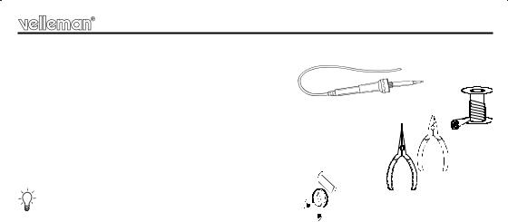
1.1 Make sure you have the right tools:
• A good quality soldering iron (25-40W) with a small tip.
•Wipe it often on a wet sponge or cloth, to keep it clean; then apply solder to the tip, to give it a wet look. This is called ‘thinning’ and will protect the tip, and enables you to make good connections. When solder rolls off the tip, it needs cleaning.
• Thin raisin-core solder. Do not use any flux or grease.
• A diagonal cutter to trim excess wires. To avoid injury when cutting excess leads, hold the lead so they cannot fly towards the eyes.
•Needle nose pliers, for bending leads, or to hold components in place.
• Small blade and Phillips screwdrivers. A basic range is fine.
0. 0 0 0
For some projects, a basic multi-meter is required, or might be handy
1.2Assembly Hints : 
Make sure the skill level matches your experience, to avoid disappointments.
Follow the instructions carefully. Read and understand the entire step before you perform each operation.
Perform the assembly in the correct order as stated in this manual
Position all parts on the PCB (Printed Circuit Board) as shown on the drawings.
Values on the circuit diagram are subject to changes.
Values in this assembly guide are correct*
Use the check-boxes to mark your progress.
Please read the included information on safety and customer service
* Typographical inaccuracies excluded. Always look for possible last minute manual updates, indicated as ‘NOTE’ on a separate leaflet.
3

Assembly hints
1.3 Soldering Hints :
1- Mount the component against the PCB surface and carefully solder the leads
2- Make sure the solder joints are cone-shaped and shiny
3- Trim excess leads as close as possible to the solder joint
AXIAL COMPONENTS ARE TAPED IN THE CORRECT
MOUNTING SEQUENCE !
REMOVE THEM FROM THE TAPE ONE AT A TIME !
You will find the colour code for the resistances and the LEDs in the HALG (general manual) and on our website: http://www.velleman.be/common/service.aspx
4
 Loading...