


DVM8 40
Multifunctional Digital Multimeter Multifunctionele Digitale Multimeter Multimètre numérique m ultifonctions Multímetro digital multif unción Multifunktionales Digital multimeter
USER MA NUAL |
3 |
GEBRUIKERSHANDLEIDING |
11 |
NOTICE D ’EMPLOI |
20 |
MANUAL DEL USUARIO |
28 |
BEDIENUN GSANLEITUNG |
37 |

DVM840
1 |
LCD display |
2 |
RANGE and FUNCTION switch |
3 |
"10A" jack |
4 |
"COM" jack |
5 |
"mAVΩ" jack |
|
|
1 |
lcd display |
2 |
BEREIK en FUNCTIE schakelaar |
3 |
"10A" jack |
4 |
"COM" jack |
5 |
" mAVΩ" jack |
|
|
1 |
Afficheur LCD |
2 |
sélecteur de FONCTION et de PLAGE |
3 |
Connexion "10A" |
4 |
Connexion "COM" |
5 |
Connexion " mAVΩ" |
|
|
1 |
Pantalla LCD |
2 |
selector de FUNCIÓN y de RANGO |
3 |
Conexión "10A" |
4 |
Conexión "COM" |
5 |
Conexión "mAVΩ" |
|
|
1 |
LC Display |
2 |
Funktions und Bereichsschalter |
3 |
"10A" BUCHSE |
4 |
"COM" BUCHSE |
5 |
"mAVΩ" BUCHSE |
©COPYRIGHT NOTICE The copyright to this manual is owned by Velleman nv. All worldwide rights reserved. No part of this manual or may be copied, reproduced, translated or reduced to any electronic medium or otherwise without the prior written consent of the copyright holder.
©AUTEURSRECHT Velleman nv heeft het auteursrecht voor deze handleiding. Alle wereldwijde rechten voorbehouden. Het is niet toegestaan om deze handleiding of gedeelten ervan over te nemen, te kopiëren, te vertalen, te bewerken en op te slaan op een elektronisch medium zonder voorafgaande schriftelijke toestemming van de rechthebbende.
©DROITS D’AUTEUR SA Velleman est l’ayant droit des droits d’auteur pour cette notice. Tous droits mondiaux réservés. Toute reproduction, traduction, copie ou diffusion, intégrale ou partielle, du contenu de cette notice par quelque procédé ou sur tout support électronique que se soit est interdite sans l’accord préalable écrit de l’ayant droit.
©DERECHOS DE AUTOR Velleman NV dispone de los derechos de autor para este manual del usuario. Todos los derechos mundiales reservados. Está estrictamente prohibido reproducir, traducir, copiar, editar y guardar este manual del usuario o partes de ello sin previo permiso escrito del derecho habiente.
©URHEBERRECHT
Velleman NV besitzt das Urheberrecht für diese Bedienungsanleitung. Alle weltweiten Rechte vorbehalten.
ohne vorherige schriftliche Genehmigung des Urhebers ist es nicht gestattet, diese Bedienungsanleitung ganz oder in Teilen zu reproduzieren, zu kopieren, zu übersetzen, zu bearbeiten oder zu speichern.
18.10.2010 |
2 |
©Velleman nv |
DVM840
User ma nual
1. Introduction
To all residents of the European Union
Importan t environmental information about th is product
This symbol on the device or the packa ge indicates that disposal of the device after its lifecycle could harm th e environment. Do not dispose of the unit (or batteries) as unsorted municipal waste; it should be taken to a
s pecialized company for recycling. This device should be returned to your distributor or to a l ocal recycling servic e. Respect the loca l environmental r ules.
If in doubt, contact your loca l waste disposal a uthorities.
Thank you for choosing Vellem an! Please read th e manual thoroughl y before bringing this device int o service. If the device was damaged in transit, do not install or use it and contact your dealer.
Refer to th e Velleman® Servic e and Quality Warranty on the last p ages of this manual.
2. Used symbols
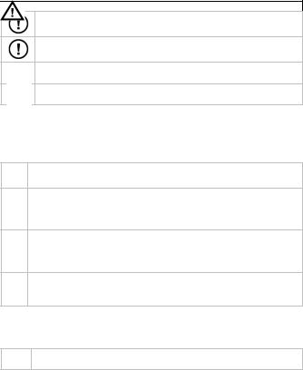
This symbol indicates: Read instructi ons
Not reading the instructions and man ual can lead to dam age, injury or death.
This symbol indicates: Danger
A hazardous condit ion or action that may result in injury or death
This symbol indicates: Risk of danger/damage
Risk of a hazardous condition or actio n that may result in damage, injury or death
This symbol indicates: Attention; imp ortant information
Ignoring this inform ation can lead to h azardous situations.
AC (Alternating Cur rent)
DC (Direct Current)
Both AC and DC
Double insulation (class II protection)
Earth
Fuse
Diode
Continuity
3. W arnings and s afety Instructions
Read this manual thoroughly. Familiarise yourself with t he functions of the device before actually using it.
Only use the device for its intended purpose. Using the d evice in an unauthorized way will void the warranty. Damage caused by disregard of
18.10.2010 |
3 |
©Velleman n v |

DVM840
certain guidelines in this manual is not covered by the warranty and the dealer will not accept responsibility f or any ensuing defects or problems.
Follow the instructions below to guar antee a safe use of the meter and all its functionalities.
During use of the m eter, respect all directives concerning protection against electroshocks and misuse. Never exceed the indicated li mits.
WARNING:
This instrument does not contain ope rator servicable parts. Service by qualified persons only.
Remark: refer to th e warning on the b ack of the meter (top).
WARNING: To avoid electrical shock opening case. To p revent fire, install Remark: refer to th e warning on the
always remove the test leads prior to fuses with AMP/VO LT rating as shown. b attery compartme nt
Keep the device aw ay from children and unauthorised users.
Protect thi s device from shock s and abuse. Avoid brute force when operating.
Avoid cold, heat and large tem perature fluctuati ons. When the unit is moved fr om a cold to a warm location, leave it switched off until it has reached room temperatur e. This to avoid co ndensation and measuring errors.
This is an installation category CAT III 600V measuring i nstrument. Never use this equipment in a higher category than indicated. R efer to §4
Overvoltage /installation category.
Pollution degree 2 device. For indoor use only. Keep this device away from rain, moisture, spla shing and dripping liquids. Not for industrial use. Refer t o §5 Pollution degree.
Before each use, m ake sure the test p robes are in good condition. Always place your fingers behind the protective edges of the tes t probes while measuring! Never touch free terminals when the meter is connected to a circuit.
Make sure the meter is in the appropriate measuring ran ge before connecting it to a t est circuit.
Risk of electric shock during operation. Be very careful w hen measuring liv e circuits. Use extrem e caution when measuring voltages h igher than 60Vdc or 30Vac rms.
Do not measure circuits that may contain voltages > 600V
Do not measure cu rrent in circuits wi th voltages > 250V
Do not conduct re sistance, diode or continuity measurements on live circuits. For testin g transistors use th e included adaptor socket.
When measuring currents up to 10A, max. 15s continuou s measurement followed by a 15 minutes break betwe en 2 measuremen ts.
18.10.2010 |
4 |
©Velleman n v |
DVM840
When carrying out measurements on a TV set or switchin g power circuits, always be aware th at high amplitude voltage pulses at the test points might damage the meter.
Do not replace int ernal parts yourself. Replace damaged or lost accessories by identical ones w ith the same specifications. Order sp are accessories e.g. test probes at your dealer.
Switch off the meter and remove test probes prior to re placing the battery or fuses.
All modifications of the device are forbidden for safety reasons. Damage caused by user modifications to the device is not covered by the warranty.
4. Overvoltage/in stallation cat egory
DMMs ar e categorized depe nding on the risk an d severity of transient overvoltage that might occur at the point of test. Transients are short lived bursts of energy induced in a system, e.g. caused by lightning strike on a power line.
The existi ng categories according EN 61010 1 are:
A CAT I rated meter is suitable for meas urements on prote cted electronic CAT I circuits which are not directly connected to mains power, e.g. electronics
circuits, control signals…
A CAT II rated meter is suitable for meas urements in CAT I environments and m ono phase applianc es which are conne cted to the mains by means of a plug CAT II and circuits in a norm al domestic environment, provided th at the circuit is at le ast 10m apart from a CAT III or 20m apart from a CAT IV environment. E.g.
household appliances , portable tools…
A CAT III rated meter is suitable for measurements in CAT I and CAT II environments, as well as for measureme nts on (fixed) mono or poly phased
CAT III appliances which are at least 10m apart from of a CAT IV e nvironment, and for m easurements in or on distribution level equipment (fuse b oxes, lighting circuits, electric ovens).
A CAT IV rated meter is suitable for measuring in CAT I , CAT II and CAT III CAT IV environments as well as on the primary supply level.
No te that for all mea surements on equi pment for which the supply cables run outdoors (either overhead or underground) a CAT IV meter must be used.
Warning:
This device was designed in a ccordance with EN 61010 1 installatio n category CAT III 600V. This implies that certain restrictions in us e apply that are rel ated to voltages and voltage pe aks which can occ ur within the enviro nment of use. Refe r to the table above.
This device is only s uitable for measure ments up to 600V in a CAT III
environment.
5.Pollution degre e
IEC 61010 1 specifies differe nt types of pollutio n environments, fo r which different protective measures are nec essary to ensure safety. Harsher envir onments require more prot ection, and the pro tection against the pollution which is to be found in a certain environment depends mainly on the ins ulation and the enclosure properties. The pollution degree rating o f the DVM indicates in which environ ment the device may be used.
18.10.2010 |
5 |
©Velleman n v |
|
DVM840 |
Pollution |
No pollution or only dry, nonconductive pollution occurs . The pollution has |
degree 1 |
no influence (only to be found in her metically sealed en closures). |
Pollution |
Only nonconductiv e pollution occurs. Occasionally, temp orary conductivity |
degree 2 |
caused by conden sation is to be expected (home and office environments |
|
fall under this category). |
Pollution |
Conductive pollution occurs, or dry n onconductive pollution occurs that |
degree 3 |
becomes conductive due to condensa tion that is to be expected (industrial |
|
environments and environments exp osed to outside air but not in contact |
|
with precipitation). |
Pollution |
The pollution gene rates persistent conductivity caused b y conductive dust |
degree 4 |
or by rain or snow. (exposed outdoor environments and environments |
|
where high humidity levels or high concentrations of fin e particles occur) |
Warning:
This device was designed in a ccordance with EN 61010 1 pollution degree 2. This implies that certain restrictions in use apply that are related to pollution which can occur with in the environment of use. Refer to th e table above.
This device is only s uitable for measur ements in Pollution degree class 2 environments.
6. M aintenance / battery and fuse replacement
W ARNING: To avoid electrical shock al ways remove the te st leads prior to opening case. To pre vent fire, install fu ses with AMP/VOLT rating as shown. Remark: refer to the warning on the back of the meter
Do not replace internal parts yourself. Replace damaged or lost accessories by identical ones wit h the same specific ations. Order spar e accessories e.g. t est probes at your d ealer.
Switch off the meter and remove test l eads prior to replacing the battery or f uses.
a. General maintenance:
• Wipe th e device regularly with a moist, lint free cloth. Do not use alcohol, solvents or abrasive products.
b. Battery replacement
•Replace the battery as soon as the “  ” indication appears on t he display. Low/ba d batterie s can produce fals e readings.
•Switch off the multi meter.
•Remov e test probes from the circuit under test. Remove all test leads from the input jacks.
•Release the screw at the back of the meter an d gently open the battery compartment.
•Replace the battery (9V 6LF22). Do not use re chargeable batteries. Insert following the righ t polarity.
•Close th e battery compartment and reseat the screw.
c. Fuse re placement
•The fuse rarely needs to b e replaced and a bl own fuse is almost always caused by a human error.
•Switch off the multi meter.
•Remov e test probes from the circuit under test. Remove all test leads from the input jacks.
•Release the screw at the back of the meter an d gently open the battery
18.10.2010 |
6 |
©Velleman n v |
DVM840
compartment.
•Release the 2 screws under the battery cover.
•Gently remove the front plate from the housing.
•Fuses are located at the bo ttom of the PCB, 200mA/250V left, 1 0A/250V right (both 5x20m m).
•Close th e housing and tighten the 2 screws.
•Close th e battery compartment and reseat the screw.
7. Fro nt panel Description
Refer to t he illustrations on p age 2 of this manual.
8. Operating instr uctions
R isk of electric shock during operation. Be very careful when measuring live circuits.
B efore measuring, always make sure th e meter and/or tes t probes are not d amaged and verify the connections, s elected function and range.
•Never e xceed the limit val ue for protection. This limit value is listed separately in the specifications for each range of measure ment.
•Do not touch unused terminals when the met er is linked to a cir cuit which is being tested.
•Only use the meter in the i ndicated overvoltage/installation cate gory. Never measure voltages that might exceed the indicated category values.
•When a measuring range is unknown, always select the highest possible range and lower t o the appropriate range.
•Disconn ect the test leads from the tested circuit before rotating the range selector in orde r to change functio ns.
•When carrying out measur ements on a TV se t or switching powe r circuits, always remember that high amplitude voltage pulses at the test points might damage the meter.
•Always be careful when w orking with voltages above 60Vdc or 30Vac rms. Keep your fin gers behind the pr obe barriers at all times during measurement.
•Do not measure current in circuits with volta ges > 250V
•Never p erform resistance, diode or continuity measurements on live circuits. Make sure all capacitors in the circuit are discharged.
8.1 DC Voltage measure ments
 D o not measure cir cuits where voltage s > 600V CAT III may occur.
A lways be careful when working with voltages above 60V dc or 30Vac rms.
K eep your fingers b ehind the probe ba rriers at all times d uring measurement . D o not touch unused terminals when t he meter is linked to a circuit which is b eing tested.
1.Connect the black test lea d ( ) to the "COM" jack and the red test lead (+) to the "mAVΩ" jack.
2.Select the appropriate V  range with the F UNCTION switch. W hen the measuring range is unknown, always select the highest p ossible range and lower to the appropriate range.
3.Connect the test leads to the circuit.
18.10.2010 |
7 |
©Velleman n v |

DVM840
4. The measured value and t he polarity of the re d test lead are dis played on the LCD.
8.2 AC Voltage measure ments
 D o not measure cir cuits where voltage s > 600V CAT III may occur.
A lways be careful when working with voltages above 60V dc or 30Vac rms.
K eep your fingers b ehind the probe ba rriers at all times d uring measurement . D o not touch unused terminals when t he meter is linked to a circuit which is b eing tested.
1.Connect the black test lea d ( ) to the "COM" jack and the red test lead (+) to the "mAVΩ" jack.
2.Select the appropriate V range with the FUN CTION switch. Wh en the measuring range is unknown, always select the highest p ossible range and lower to the appropriate range.
3.Connect the test leads to the circuit.
4.The measured value appe ars on the LCD display.
8.3 DC c urrent measurem ents
 D o not measure current in circuits with voltages > 250V
C urrent measurements: mA jack max. 200mA; for measurements up to 10A u se the 10A jack. When measuring curr ents up to 10A, ma x. 15s continuous m easurement follo wed by a 15 minutes break between 2 measurements.
A lways be careful when working with voltages above 60V dc or 30Vac rms.
K eep your fingers b ehind the probe ba rriers at all times d uring measurement .
1.Connect the black test lea d ( ) to the "COM" jack and the red test lead (+) to the "mAVΩ" jack for measure ments of max. 200m A or to the "10A" j ack for measurements between 200mA and 10A.
2.Select the A  range with the FUNCTION sw itch. For measure ments < 200mA, when t he measuring range is unknown, alway s select the highest possible range and lower t o the appropriate range.
3.Connect the test leads IN S ERIES with the load under measurement.
4.The polarity of the red tes t lead and the mea sured current are displayed on the LCD.
8.4 Mea suring Resistanc e
Do not perform resistance measurements on live circuits and make sure all c apacitors are completely discharged.
1.Connect the black test lea d ( ) to the "COM" jack and the red test lead (+) to the "mAVΩ" jack.
2.Select the Ω range with the FUNCTION switc h. When the measuring range is unknow n, always select the highest possible r ange and lower to the appropriate range.
3.Connect the test leads with the resistance and read the value fro m the display.
Remarks :
The meter may need a few seconds to pro duce a stable readin g for resistance meas urements in exces s of 1MΩ.
The o ver range indicatio n (“1.”) will appea r on the display if t he input is not
18.10.2010 |
8 |
©Velleman n v |
DVM840
connected or if the resis tance being measured exceeds the max. value of the selected range.
8.5 Testing Diodes
D o not perform diode measurements on live circuits and make sure all capacitors are com pletely discharged.
1.Conn ect the black test l ead ( ) to the "COM " jack and the red test lead (+) to the "mA VΩ" jack.
2.Selec t the  /
/  rang e with the FUNCTION switch.
3.Conn ect the red test lead to the anode and the black test lead to the cathode of the diode to be tested. The forward voltag e drop is now displ ayed. When the connection is reversed, the display shows “ 1”.
8.6 Audible continuity test
D o not perform continuity measurem ents on live circuits and make sure all capacitors are com pletely discharged.
1.Conn ect the black test l ead ( ) to the "COM " jack and the red test lead (+) to the "mA VΩ" jack.
2.Selec t the  /
/  rang e with the FUNCTION switch.
3.Conn ect the test probes to two random points of the circuit t o be tested. The
incorporated buzzer is activated if the resistance between the two test probes is lower than 70±20Ω.
9. Te chnical specifications
Regulatio ns concerning environment of use:
Use this m eter only for measurements in CAT I, CAT II and CAT III environments (see §4)
Use this m eter only in a pollu tion degree 2 envir onment (see §5)
Ideal tem perature |
|
0~40°C |
|||
Ideal relative humidity |
|
<80% |
|||
9.1. |
General |
|
|
|
|
|
|
|
|
|
|
Max. Voltage |
|
600V CAT III |
|||
Display |
|
3 ½ digit LCD, 2 to 3 samples/sec. |
|||
Fuse Prot ection |
200mA range: 200 mA/250V (5x20mm) |
||||
10A range: 10A/25 0V (5x20mm) |
|||||
|
|
||||
Power Su pply |
9V alkaline battery 6LR61 |
||||
Ranging M ethod |
manual |
||||
Polarity Indication |
" " is displayed |
||||
Overrang e Indication |
" 1 . " is displayed automatically |
||||
Battery Lo w Indication |
" |
|
" is displayed |
||
|
|||||
Operating Temperature |
0°C to 40°C |
||||
Storage T emperature |
10°C to 50°C |
||||
Dimensio ns |
|
145 x 85 x 30mm |
|||
Weight |
|
±170g (incl. battery) |
|||
18.10.2010 |
9 |
©Velleman n v |

DVM840
9.2.DC Voltage
Range |
Resolution |
Accuracy |
|
200mV |
100µV |
|
|
2V |
1mV |
±(0.5% of rdg + 4 digits) |
|
20V |
10mV |
||
|
|||
200V |
100mV |
|
|
600V |
1V |
±(1.0% of rdg +5 digits) |
Input Impedance: 1MΩ for all ranges
9.3. |
AC Voltage |
|
|
|
|
Range |
|
Resolutio n |
Accuracy |
|
200V |
|
100mV |
±(1.2% of rdg +10 digits) |
|
600V |
|
1V |
|
|
|
|
||
Input Impedance: 1MΩ for all ranges |
|
|
||
Frequency Range: 40 to 400H z |
|
|
||
9.4.DC Current
Range |
Resolution |
Accuracy |
|
200µA |
0.1µA |
|
|
2mA |
1µA |
±(1.5% of rdg +3 digits) |
|
20mA |
10µA |
||
|
|||
200mA |
100µA |
|
|
10A |
10µA |
±(2.0% of rdg + 5 digits) |
When measuring currents up to 10A, max. 15s continuous measur ement followed by a 15 minute s break between 2 measurements.
Overload Protection: 200mA range F0.2A/250V – 10A range fuse F10A/250V
9.5.Resistance
Range |
Resolution |
Accuracy |
|
200Ω |
0.1Ω |
±(0.8% of rdg + 5 digits) |
|
2kΩ |
1Ω |
|
|
20kΩ |
10Ω |
±(0.8% of rdg + 3 digits) |
|
200kΩ |
100Ω |
||
|
|||
2MΩ |
1kΩ |
|
|
20MΩ |
10kΩ |
±(1.0% of rdg + 15 digits) |
Overload Protection: DC250V or AC peak value
Note: in r ange 200Ω, short circuit test leads to d etermine lead resi stance, than subtract t his value from the measured value.
9.6.Diode and aud ible continuity test
|
Range |
|
para meters |
|
|
|
|
|
Built in buzzer sound s if resistance < 70±20Ω |
|
|
|
|
|
Forward test current(DC): ± 1mA |
|
|
|
|
|
Reversed test voltage: ± 3Vdc |
|
|
|
Overload Protection: DC250V or AC peak value |
|
|
||
|
|
|
|
|
|
18.10.2010 |
10 |
©Velleman n v |
|||
DVM840
10.Accessories
•set of test leads
•1 battery of 9V
•1 user manual
Use this device with original accessories only. Velleman nv cannot be held responsible in the event of d amage or injury resulted from (incor rect) use of this device.
For more info concerning this product and the latest version of this user manual, please visit our website ww w.velleman.eu.
The infor mation in this man ual is subject to ch ange without prior notice.
Ge bruikersha ndleiding
1. Inleiding
Aan alle i ngezetenen van de Europese Unie Belangrijk e milieu informatie betreffende dit product
Dit symbool op het toestel of de verpa kking geeft aan da t, als het na zijn levenscyclus wordt weggeworpen, dit toestel schade kan toebrengen aan het milieu. Gooi dit toestel (en eventuele batterijen) niet bij het gewone huishoudelijke afval; het moet bij een gespecialiseerd be drijf terechtkomen voor recyclage. U m oet dit toestel naar uw verdeler of naar een lokaal recyclagepunt brengen. Respecteer de plaatselijke milieuwetgeving.
Hebt u vr agen, contacteer d an de plaatselijke a utoriteiten betreffend de verwijdering.
Lees deze handleiding grondig voor u het toestel in gebruik neemt. Werd het toestel beschadigd tijdens het trans port, gebruik het da n niet en raadplee g uw dealer.
Raadpleeg de Velleman® service en kwaliteitsg arantie achteraan d eze handleiding.
2. Gebruikte symbolen
Dit symbool staat voor instructies le zen:
Het niet lezen van deze instructies en de handleiding ka n leiden tot beschadiging, lets el of de dood
Dit symbool betek ent gevaar:
Gevaarlijke toesta nd of actie die kan leiden tot letsel of de dood
Dit symbool betek ent risico op gevaa r/schade:
Risico op het ontstaan van een gevaarlijke toestand of a ctie die kan leiden tot schade, letsel o f de dood
Dit symbool betek ent aandacht, bela ngrijke informatie:
Het niet in acht nemen van deze infor matie kan leiden t ot een gevaarlijke toestand
AC (wisselstroom)
DC (gelijkstroom)
zowel wissel als gelijkstroom
Dubbele isolatie (klasse II beschermin g)
18.10.2010 |
11 |
©Velleman n v |

DVM840
Aarding
Zekering
Diode
Continuïteit
3. W aarschuwinge n en veiligheidsvoorschriften
Lees deze handleidi ng grondig, leer eer st de functies van het toestel kennen voor u het gaat gebr uiken.
G ebruik het toestel enkel waarvoor he t gemaakt is. Bij on oordeelkundig gebruik vervalt de garantie. De garanti e geldt niet voor sc hade door het n egeren van bepaalde richtlijnen in de ze handleiding en uw dealer zal de verantwoordelijkheid afwijzen voor de fecten of problemen die hier rechtstreeks verband mee houden.
V olg de richtlijnen hieronder om een v eilig gebruik te gara nderen en alle functies van de meter ten volle te benu tten.
R especteer tijdens h et gebruik van de meter alle richtlijnen aangaande b eveiliging tegen el ektroshocks en verk eerd gebruik. De aangegeven limietwaarden mog en nooit overschre den worden
WAARSCHUWING:
D it toestel bevat ge en door de gebruik er vervangbare ond erdelen. Reparaties m ogen alleen uitgev oerd worden door gekwalificeerd personeel.
O pmerking: dit is de vertaling van de w aarschuwing die zich bovenaan op de achterkant van het t oestel bevindt.
WAARSCHUWING:
O m elektrische scho kken te vermijden, verwijder de tests noeren alvorens de b ehuizing te openen . Om brand te voorkomen, gebruik en kel zekeringen met d ezelfde specificatie s zoals aangeduid.
O pmerking: dit is de vertaling van de w aarschuwing die zich onderaan op de achterkant van het t oestel bevindt.
H oud dit toestel uit de buurt van kinderen en onbevoegde n.
Bescherm he t toestel tegen schokken. Vermijd bru te kracht tijdens d e bediening.
Vermijd kou de, hitte en grote t emperatuursschommelingen, Als het toestel van e en koude naar een warme omgeving verplaatst wordt, laat het toestel dan eerst voldoende op temperatu ur komen. Dit om meetfouten en condensvormin g te vermijden.
D it is een installatie categorie CAT III 60 0 V meetinstrume nt. Gebruik dit toestel nooit in een hogere CAT dan aangegeven. Zie §4 Overspanning
/installatiecategori e.
Vervuilingsg raad 2 toestel, enk el geschikt voor geb ruik binnenshuis! Stel dit toestel niet bloot aan stof, regen, vochtigheid en opspattende vloeistoffen. Niet geschikt voor industrieel gebruik. Zie §5
Vervuilingsgraad
C ontroleer voor gebruik indien de meetsnoeren in goede staat verkeren. H oud tijdens meting en uw vingers achter de beschermingsrand van de
18.10.2010 |
12 |
©Velleman n v |

DVM840
m eetpennen! Raak geen vrije meetbussen aan wanneer de meter met een circuit is verbonden.
Let erop dat de meter zich in de juiste stand bevindt alvorens deze te verbinden met het testcircuit.
Elektrocutiegevaar tijdens het gebruik van deze multimet er. Wees voorzichtig tijdens het meten v an een circuit onder spanning. Wees uiterst voorzichtig bi j m etingen > 60 VDC of 30 V RMS AC.
Meet niet aan circuits waarin spanningen kunnen voorko men > 600 V.
Meet geen stroom in circuits met een s panning > 250 V.
V oer geen weerstand , diode of contin uïteitsmetingen ui t in circuits waarop spanning aanwezig is, of zou kunnen vo orkomen. Gebruik voor transistortests d e meegeleverde ad apter.
B ij stroommetingen tot 10 A max. 15 s ec. aaneensluitend meten, telkens 15 m in. wachten tusse n 2 metingen.
Wees voorzichtig bij metingen aan toe stellen zoals tv's of schakelende voedingen, Let op bij metingen op circu its zoals TV’s of sc hakelende voedingen, er kunne n spanningspieken voorkomen die de meter kunnen b eschadigen
D e gebruiker mag g een inwendige onderdelen vervangen. Vervang
b eschadigde of verl oren accessoires enkel door accessoire s van hetzelfde type of met dezelfd e specificaties. Bestel reserveaccessoires zoals
m eetsnoeren bij uw dealer.
Schakel de meter uit en verwijder de te stsnoeren vóór u d e batterij of zekering vervangt.
O m veiligheidsrede nen mag u geen wijzigingen aanbrenge n. Schade door
wijzigingen die de g ebruiker heeft aang ebracht valt niet onder de garantie.
4.Overspanning /installatiecategorie
DMM’s w orden opgedeeld v olgens het risico op en de ernst van spanningpieken die kunnen o ptreden op het mee tpunt. Spanningspieken zijn kortston dige uitbarstingen van energie die geïnduceerd worden in een systeem door bvb. blikseminslag op een hoogspanningslijn.
De bestaande categorieën vo lgens EN 61010 1 z ijn:
CAT I E en CAT I meter is g eschikt voor meting en op beschermde elektronische circuits die niet rechtstreeks verbonden zijn met het lichtnet, bvb.
Elektronische schake lingen, stuursignalen…
CAT II E en CAT II meter is geschikt voor metingen in CAT I omgevingen en op
e nkelfasige apparate n die aan het licht net gekoppeld zijn door middel van een st ekker en circuits in een normale huise lijke omgeving, op voorwaarde dat het circuit minstens 10m verwijderd is van een CAT III omgevin g, en minstens 20 m v an een CAT IV omg eving. Bvb. Huishou dapparaten, draagbare
g ereedschappen ...
CAT III E en CAT III meter is geschikt voor metin gen in CAT I en CA T II omgevingen, alsook voor metingen aan enkel en meerfasige (vaste) toe stellen op meer dan 10 m van een CA T IV omgeving, en metingen in of aa n distributiekasten
18.10.2010 |
13 |
©Velleman n v |

DVM840
(zekeringkasten, verl ichtingscircuits, ele ktrisch fornuis).
CAT IV E en CAT IV meter is geschikt voor metin gen in CAT I, CAT II en CAT III omgevingen alsook metingen op het primaire toevoerniveau.
M erk op dat voor m etingen op kringen waarvan de toevoe rkabels buitenshui s lo pen (zowel boven als ondergronds) een CAT IV meter moet gebruikt
worden.
Waarschu wing:
Dit toestel is ontworpen conf orm EN 61010 1 installatiecategorie C AT III 600V. Dit houdt bep aalde gebruiksbeperkingen in die te m aken hebben met voltages en spanningspieken die kunnen voorkomen in de gebruiksomgeving, zie tabel hierboven.
Dit toestel is enkel geschikt voor metin gen tot max. 600V in een CAT III omgeving.
5. Vervuilingsgraad (pollution d egree)
IEC 61010 1 specifieert verschillende types vervuilingsgraden welk e bepaalde risico’s met zich meebrengen. Iedere vervuilingsgraad vereist specifieke beschermingsmaatregelen. O mgevingen met een hogere vervuiling sgraad hebben ee n betere bescherming nodig tegen mogelijke invlo eden van de versc hillende types vervuiling die in deze omgeving kunnen voorko men. Deze bescher ming bestaat hoofdzake lijk uit aagepaste i solatie en een aangepaste behuizing. D e opgegeven Pollution degree waarde geeft aan in welke om geving dit apparaat veilig gebruikt kan worden.
Pollution |
Omgeving zond er, of met enkel dro ge niet geleidend e vervuiling. De |
degree 1 |
voorkomende vervuiling heeft gee n invloed (Komt en kel voor in |
|
uitzondelijke om gevingen). |
Pollution |
Omgeving met e nkel niet geleiden de vervuiling, Uitzonderlijk kan |
degree 2 |
condensatie voo rkomen. (bvb. huis houdelijke en kantooromgeving) |
Pollution |
Omgeving waar geleidende vervuiling voorkomt, of droge niet geleidende |
degree 3 |
vervuiling die ge leidend kan worden door condensati e. (industriële |
|
omgevingen en omgevingen die bl ootgesteld worden aan buitenlucht |
|
zonder rechtstr eeks contact met n eerslag |
Pollution |
Omgeving waar frequent geleidend e vervuiling voork omt, bvb. |
degree 4 |
veroorzaakt doo r geleidend stof, re gen of sneeuw (in openlucht en |
|
omgevingen met een hoge vochtigheidsgraad of hoge concentraties fijn |
|
stof). |
Waarschu wing:
Dit toestel is ontworpen conf orm EN 61010 1 ve rvuilingsgraad Pollution degree 2. Dit houdt bep aalde gebruiksbeperkingen in die te m aken hebben met de pollutie die kan voorkome n in de gebruiksom geving, zie tabel hierboven.
Dit toestel is enkel geschikt voor gebr uik in omgevingen met Pollution degree 2 classificatie
6. Onderhoud, bat terijen & zekeringen verv angen
W AARSCHUWING: om elektrische schokken te vermijden, verwijder de t estsnoeren alvorens de behuizing te o penen. Om brand t e voorkomen gebruik enkel zekeringen met dezelfde specificaties als aa ngeduid
O pmerking: dit is de vertaling van de waarschuwing die zic h onderaan op de
18.10.2010 |
14 |
©Velleman n v |

DVM840
achterkant van het toestel bevindt
De gebruiker mag ge en onderdelen vervangen. Bestel eventuele r eserveonderdelen b ij uw dealer.
Koppel de testsnoeren los van het meetcircuit en trek de stekkers uit de aansluitbussen vooraleer de batterijen of de zekering te v ervangen.
a. Algeme en onderhoud:
• Reinig h et toestel enkel m et een zachte niet p luizende en weinig vochtige doek (ev . met ee n onschadelijk detergent). Gebruik no oit agressieve schu ur of oplosmiddelen.
b. Vervangen van de batterij:
•Vervan g de batterij als het  symbool op h et scherm verschijnt, slechte batterije n kunnen foutieve meetresultaten opleveren.
•Schakel het toestel uit
•Koppel de testsnoeren los van het meetcircuit en trek de stekke rs uit de
aanslui tbussen.
• Draai de schroef achteraa n de meter los en open voorzichtig het batterijvak.
•Vervan g de batterij (9V 6L F22, gebruik geen o plaadbare batterij en en let op de polarite it)
•Sluit het batterijvak en draai de schroef vast.
c. Vervan gen van de zekering:
•Zekeringen moeten slecht s zelden worden vervangen en een ka potte zekering is bijna altijd het gevolg van een menselijke fout.
•Schakel het toestel uit
•Koppel de testsn oeren los van het meetcircuit en trek de stekkers uit de aansluitbussen.
• Draai de schroef achteraa n de meter los en open voorzichtig het batterijvak.
•Draai de 2 schroeven bovenaan het batterijva k los.
•Open de multimeter voorzichtig.
•De zeke ringen bevinden zich onderaan de printplaat. Links: 200 mA/250V; rechts: 10A/250V right (beiden 5x20mm).
•Sluit de behuizing en draai de 2 schroeven va st.
•Sluit het batterijvak en draai de schroef vast.
7. Beschrijving van het frontpa neel
Raadpleeg de figuur op pagin a 2 van deze handleiding.
8. Bedieningsinstructies
Elektrocutiegevaar tijdens het gebruik van deze multimeter.
Wees voorzichtig tijdens het meten va n een circuit onder spanning.
C ontroleer vooraleer te meten altijd indien de aansluitingen, de functie en h et bereik correct zijn ingesteld en indien het toestel en/o f de testsnoeren n iet beschadigd zijn
•Oversc hrijd nooit de grenswaarden! Deze waarden worden verm eld in de specificaties van elk meetb ereik.
•Raak ge en ongebruikte ingangsbussen aan w anneer de meter ge koppeld is aan een schakeling die u aan het testen bent.
•Gebruik de meter enkel vo or het meten in de aangeduide meetcategorie installaties en meet geen voltages die de aangeduide waarden kunnen overschrijden.
18.10.2010 |
15 |
©Velleman n v |
 Loading...