

P
W
W
B
O
M
E
A
N
T
/
-
I
E
D
A
E
O
O
X
D
E
OT
L
D
X
O
O
O
U
A
5
A
VD
750
750
STRO
ESTR
MUSI
750S
MUSIC MUZIEK
OSCOPE
BOSCOP
KGESTEU
DMX-CO
/ DMX-G
750W PIL
O DMX C
RTES DM
NTROLLE
STUURD
É PAR
NTROLA
-STROB
STROB
STROB
A MUSIQ
O POR L
SKOP (7
SCOPE
SCOOP
E / DMX
MÚSIC
0W)
750W
USER
GEBRU
NOTIC
MANU
BEDIE
ANUAL
IKERSHAN
D’EMPLOI
L DEL USU
UNGSANLE
LEIDING
RIO
ITUNG
2
5
9
1
2
1
6
t
e
a
u
o
I
f
g
a
v
e
e
s
n
m
l
h
h
t
n
t
e
e
a
u
a
.
e
e
d
u
o
H
s
c
u
s
i
m
r
e
m
e
t
u
p
e
d
w
o
e
0
f
i
n
t
D
e
a
a
s
n
r
e
t
n
t
g
s
c
d
t
s
c
g
o
a
Q
p
h
x
s
5
A
m
i
t
a
h
o
i
d
f
o
d
d
w
p
p
h
e
e
n
m
r
t
t
g
b
b
e
c
e
t
a
t
n
p
a
0
o
t
b
T
e
m
h
e
e
c
e
e
a
V
k
u
f
t
o
a
c
a
u
o
o
e
i
y
i
h
n
1. In
To all r
Import
If in do
Thank y
service.
2. Sa
roduction
sidents of th
nt environme
This symbol on
could harm th
waste; it shoul
to your distrib
bt, contact y
u for choosing
f the device wa
ety Instru
European Un
ntal informati
the device or
environment.
be taken to a
tor or to a loca
ur local wast
QPower™! Ple
damaged in tr
tions
VDP7
USER M
ion
on about this
he package ind
o not dispose
specialized co
l recycling serv
disposal au
se read the ma
nsit, don't inst
0ST
NUAL
product
icates that disp
of the unit (or
pany for recyc
ce. Respect th
horities.
nual thoroughly
ll or use it and
osal of the devi
atteries) as un
his devic
ling.
local environ
before bringing
contact your de
ce after its life
sorted municip
should be ret
ental rules.
this device int
aler.
ycle
l
rned
• Dama
the de
• A quali
• Do not
the de
• This d
qualifi
• Make
manua
• Do not
necess
• Discon
plug o
• There
norma
• Do not
• Note t
• Keep t
• When
3. Ge
Refer to
• This d
only b
• Lightin
lives.
• Do not
• Select
minim
• Use an
• Famili
unqual
device
24.09.201
Be very caref
electroshocks
Do not touch
Keep this dev
Unplug the m
e caused by di
ler will not acc
fied technician
switch the dev
ice against da
vice falls unde
d person carry
ure that the av
l.
crimp the pow
ary.
nect the device
ly.
ay be some s
and any smok
look directly a
at damage ca
e device away
he front glass
eral Guid
he Velleman
vice is designe
used indoors
g effects are n
shake the devi
location wher
m distance of
appropriate sa
rise yourself w
ified people. A
0
l during the in
.
the device duri
ice away from
ains lead befor
regard of certa
ept responsibili
should install a
ce on immedia
age by leavin
protection cla
out the electri
ailable voltage
r cord and pro
from the main
oke or a parti
or smell will
the light sourc
sed by user m
from children
ane is damage
lines
®
Service and
for profession
ith an alternat
t designed for
ce. Avoid brute
the device is p
.5m between t
ety cable to fi
th the function
y damage that
tallation: touc
g operation as
ain and moistu
opening the h
in guidelines in
y for any ensu
d service this
ely after it has
it switched of
s I. It is theref
connection.
oes not excee
ect it against
to clean it or
ular smell whe
radually disap
e as sensitive
difications to t
nd unauthoris
d, it MUST be r
uality Warra
al use on stage
ing current of
ermanent ope
force when ins
rotected agains
e device’s light
the device (e.
of the device
may occur will
2
ing live wires
the housing h
re.
using.
this manual is
ng defects or p
evice.
been exposed
until it has rea
re essential th
the voltage s
amage. Have a
hen it is not in
n the device is
ear.
eople may go i
e device is not
d users.
placed!
ty on the last
, in discos, the
ax. 230VAC/5
ation: regular
alling or opera
extreme heat,
output and any
. VDLSC8).
efore actually
most probably
an cause life-t
ats up.
not covered by
roblems.
o changes in t
ched room tem
t the device b
ated in the spe
n authorised d
use. Handle th
activated for th
to epileptic sei
covered by th
ages of this m
tres, etc. The
Hz.
peration brea
ing the device.
dust and moist
illuminated sur
using it. Do no
e due to unpr
reatening
the warranty a
mperature. Pr
perature.
earthed. Hav
ifications of th
aler replace it i
e power cord b
e first time. Th
zure if they do.
warranty.
nual.
DP750ST sho
s will prolong t
re. Respect a
ace.
allow operatio
fessional use o
©Vellem
nd
tect
a
s
f
the
s is
uld
eir
by
f the
n nv
VDP750ST
• Use the original packaging if the device is to be transported.
• All modifications of the device are forbidden for safety reasons.
• Only use the device for its intended purpose. All other uses may lead to short circuits, burns,
electroshocks, lamp explosion, crash, etc. Using the device in an unauthorised way will void the
warranty.
4. Installation
a) Lamp
• Only fit or replace a lamp when the device is unplugged from the mains.
• Let a lamp cool down before replacing it as the temperature of a lamp can reach 700°C during
operation.
Also, do not switch the lamp back on within 10 minutes after having turned it off.
• Do not touch the lamp with your bare hands. Use a cloth to insert or remove it.
• Do not install lamps with a higher wattage than what this device was designed for.
• Replace any deformed or damaged lamp with a lamp of the same type (see “7. Technical
Specifications”):
1. Remove the glass pane's 4 screws on the front and gently remove the pane.
2. Loosen the screws on the left & right connection blocks and disconnect the wires.
3. Remove the old lamp and carefully install a new one, with the wires at the same side as with
the old lamp.
4. Connect the wires of the new lamp.
5. Carefully reposition the pane and fasten it with the 4 screws.
Remark: Do not operate the device when the glass pane is off.
b) Mounting the Device
• Have the device installed by a qualified person, respecting EN 60598-2-17 and all other applicable
norms.
• The carrying construction must be able to support 10 times the weight of the device for 1 hour without
deforming.
• The installation must always be secured with a secondary attachment e.g. a safety cable.
• Never stand directly below the device when it is being mounted, removed or serviced. Have a qualified
technician check the device once a year and once before you bring it into service.
• Install the device in a location with few passers-by that is inaccessible to unauthorised persons.
• Overhead mounting requires extensive experience: calculating workload limits, determining the
installation material to be used… Have the material and the device itself checked regularly. Do not
attempt to install the device yourself if you lack these qualifications as improper installation may result
in injuries.
• Adjust the desired inclination angle via the mounting bracket and tighten the bracket screws.
• Make sure there is no flammable material within a 50cm radius of the device.
• Have a qualified electrician carry out the electric connection.
• Connect the device to the mains with the power plug. Do not connect it to a dimming pack.
• The installation has to be approved by an expert before the device is taken into service.
5. Use
This device can be operated in manual mode or DMX mode. In manual mode, the flash speed and
dimmer function can be set manually by the DIP switches. In DMX mode, speed and dimmer function are
set by 2 DMX channels.
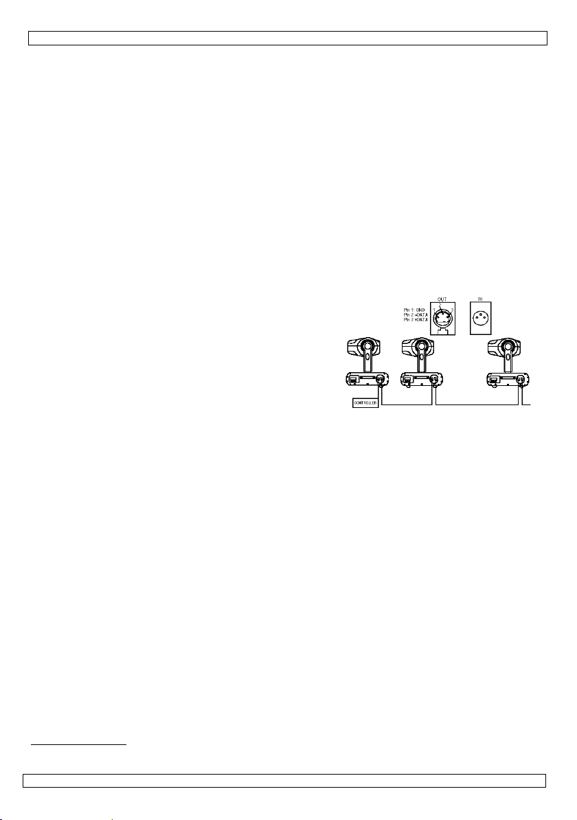
a. DMX-512 Connections
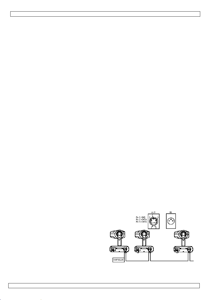
Connect the provided XLR cable to the female 3-pin
XLR output of your controller and the other side to
the male 3-pin XLR input of the VDP750ST.
Multiple VDP750STs can be linked through serial
linking. The linking cable should be two core,
screened cable with XLR input and output
connectors.
Please refer to the diagram at the right.
b. DMX-512 Chain with termination
A DMX terminator is recommended for installations where the DMX cable has to run a long distance or is
in an electrically noisy environment (e.g. discos). The terminator prevents corruption of the digital
control signal by electrical noise. This device features a built-in DMX terminator, which is activated by
24.09.2010 ©Velleman nv
3

VDP750ST
means of the red DIP switch on the device. Switch it in the ON position if the device is the last device in
the chain.
c. Projector DMX start address selection
All DMX-controlled devices need a digital start address so that the correct device responds to the signals.
This digital start address is the channel number from which the device starts to “listen” to the DMX
controller. Set the correct number by means of the DIP switches on the device.
You can use the same starting address for a whole group of devices or enter an individual one for every
device.
When all devices have the same address, all the units will “listen” to the control signal on one particular
channel. In other words: changing the settings of one channel will affect all devices simultaneously. If
you set different addresses, each device will “listen” to a separate channel number. Changing the settings
of one channel will only affect the device in question.
DMX channels:
• Ch 1: strobe rate
• Ch 2: strobe dimmer
! Warning: Ch2 to 0% and Ch1 from 10 to 85% creates a blinder effect. The level of CH1 is the dimming
level of the blinder effect. This may only last for max. 5 seconds, otherwise the lamp may get
damaged. When CH1 is higher than 85%, the strobe turns into stand-alone mode with music-controlled
function on.
d. Function selection
There are 10 DIP switches ; the way these are set determines the operation mode of the device.
DMX address setting
Set DIP switch 10 to ON (up). Now use the first 9 switches to determine the address. The 9 switches
each have a different value, which is always one more than the sum of all switches before it. This means
switch 1 has value 1, switch 2 has value 2, switch 3 has value 4, 4 is 8, 5 is 15, 6 is 32, 7 is 64, 8 is 128
and 9 is 256. Take the address you want to give to the device and start counting from switch 9 to 1,
selecting the values that need to be added along the way. Set the corresponding switches to ON. The
maximum value is 511 (all 9 switches are ON).
Test program
Switch 10 must be OFF (down).
This function allows you to perform the automatic test program (switch 9 OFF) or to set the speed and
dimmer functions yourself (switch 9 ON).
For the automatic test program, the value of the first 8 switches does not matter, as long as they are not
all ON.
In the manual program, switches 1-4 are used to set the speed and switches 5-8 are used to set the
dimmer function.
The table below indicates you the switches should be set to determine speed and dimmer function (16
levels each):
level DIP switch setting level DIP switch setting
0 (slow) OFF – OFF – OFF – OFF 8 OFF – OFF – OFF – ON
1 ON – OFF – OFF – OFF 9 ON – OFF – OFF – ON
2 OFF – ON – OFF – OFF 10 OFF – ON – OFF – ON
3 ON – ON – OFF – OFF 11 ON – ON – OFF – ON
4 OFF – OFF – ON – OFF 12 OFF – OFF – ON – ON
5 ON – OFF – ON – OFF 13 ON – OFF – ON – ON
6 OFF – ON – ON – OFF 14 OFF – ON – ON – ON
7 ON – ON – ON – OFF 15 (fast) ON – ON – ON – ON
Music control
This function sets the device to music-controlled. Switches 1-8 must be ON, switches 9 and 10 must be
OFF.
6. Maintenance
1. All screws should be tightened and free of corrosion.
2. The housing, the lenses, the mounting supports and the installation location (e.g. ceiling, suspension,
trussing) should not be deformed, modified or tampered with e.g. do not drill extra holes in mounting
supports, do not change the location of the connections …
3. Mechanically moving parts must not show any signs of wear and tear.
24.09.2010 ©Velleman nv
4
e
.
h
a
c
c
e
o
s
f
q
y
o
e
e
v
v
e
i
o
e
p
a
v
o
e
o
n
u
m
o
r
v
f
o
n
e
n
t
c
p
n
s
h
s
s
o
e
s
s
a
s
e
n
s
U
e
e
f
h
n
e
p
a
t
n
e
o
w
e
5
e
h
l
~
a
m
0
e
a
a
y
A
o
e
k
e
t
d
n
b
g
a
e
l
x
e
n
s
p
o
e
D
m
o
e
e
r
o
a
e
h
r
m
e
h
e
m
u
o
t
k
l
a
z
c
a
n
t
o
n
r
e
a
4. The el
device
5. Discon
6. Wipe t
7. There
8. Conta
7. Te
power su
circuit br
lamp
DMX in/
dimensio
weight
Use thi
event o
concern
www.h
© COPY
The cop
No part
otherwis
ctric power su
nect the device
e device regul
re no user-ser
t your dealer f
hnical Sp
pply
aker
ut
ns
device with
damage or i
ing this prod
power.eu. Th
RIGHT NOTIC
right to this
f this manual
without the p
ply cables mus
from the main
rly with a moi
iceable parts,
r spare parts if
cifications
riginal acces
jury resulted
ct and the lat
e information
E
anual is ow
r may be copie
ior written con
VDP7
t not show any
prior to maint
t, lint-free clot
part from the
necessary.
max. 230VAC
16A
750W strobe l
3-pin female/
320 x 136 x 2
4.6kg
ories only. V
from (incorre
st version of
in this manu
ed by Vellem
d, reproduced,
ent of the cop
0ST
damage. Have
nance activitie
. Do not use a
amp (see “4. I
50Hz, 16A ma
mp (order cod
ale XLR
7mm
lleman nv ca
ct) use of thi
this manual,
l is subject t
n nv. All wor
translated or r
right holder.
a qualified tec
s.
cohol or solven
nstallation”).
.
LAMP750W)
not be held r
device. For
lease visit o
change with
ldwide rights
duced to any e
nician maintai
ts.
sponsible in
ore info
r website
ut prior notic
reserved.
lectronic mediu
the
he
e.
m or
1. Inl
Aan all
Belangr
Hebt u
Dank u
toestel b
2. Ve
• De gar
dealer
mee h
• Laat e
24.09.201
eiding
ingezetenen
ijke milieu-in
Dit symbool
weggeworpe
batterijen) ni
terechtkome
recyclagepun
ragen, conta
oor uw aankoo
schadigd tijde
ligheidsin
Wees voorzic
elektroshock
Raak het toe
Bescherm dit
Ontkoppel de
antie geldt niet
zal de verantw
uden.
n geschoolde t
0
GEBR
an de Europ
ormatie betr
p het toestel o
, dit toestel sc
t bij het gewo
voor recyclag
brengen. Res
teer dan de p
! Lees deze h
s het transpor
tructies
tig bij de insta
te vermijden.
tel niet aan wa
toestel tegen r
voedingskabel
voor schade d
ordelijkheid af
chnicus dit to
IKERSH
se Unie
ffende dit pr
de verpakking
ade kan toebr
e huishoudelij
. U moet dit to
ecteer de plaat
laatselijke au
ndleiding gron
, installeer het
llatie: raak gee
neer het in ge
gen en vochti
en open dan p
or het negeren
ijzen voor def
stel installeren
5
NDLEI
duct
geeft aan dat,
ngen aan het
e afval; het m
stel naar uw v
selijke milieuw
oriteiten bet
ig voor u het t
dan niet en ra
kabels aan di
ruik is: de be
heid.
s de behuizing.
van bepaalde
cten of proble
en onderhoud
ING
als het na zijn l
ilieu. Gooi dit
et bij een gesp
rdeler of naar
tgeving.
effende de ve
estel in gebrui
dpleeg uw dea
onder stroom
uizing wordt w
ichtlijnen in de
en die hier re
n.
evenscyclus w
oestel (en eve
ecialiseerd bed
een lokaal
rwijdering.
neemt. Werd
er.
staan om dode
rm.
e handleiding
htstreeks verb
©Vellem
rdt
tuele
ijf
het
lijke
n uw
nd
n nv

VDP750ST
• Om beschadiging te vermijden, mag u het toestel niet inschakelen onmiddellijk nadat het werd
blootgesteld aan temperatuurschommelingen. Wacht tot het toestel op kamertemperatuur gekomen is.
• Dit toestel valt onder beschermingsklasse I, wat wil zeggen dat het toestel geaard moet zijn. Een
geschoolde technicus moet de elektrische aansluiting verzorgen.
• De beschikbare netspanning mag niet hoger zijn dan de spanning in de specificaties achteraan de
handleiding.
• De voedingskabel mag niet omgeplooid of beschadigd zijn. Laat uw dealer zo nodig een nieuwe kabel
plaatsen.
• Trek de stekker uit het stopcontact (trek nooit aan de kabel!) voordat u het toestel reinigt en als u het niet
gebruikt.
• Wanneer u het toestel voor het eerst gebruikt, kan dit gepaard gaan met een lichte rookontwikkeling
en een bepaalde geur. Dit is normaal en de eventuele rook of geur zal geleidelijk verdwijnen.
• Kijk niet rechtstreeks in de lichtbron. De lichtbron kan bij gevoelige mensen leiden tot een aanval van
epilepsie.
• Schade door wijzigingen die de gebruiker heeft aangebracht aan het toestel vallen niet onder de
garantie.
• Hou dit toestel uit de buurt van kinderen en onbevoegden.
• Wanneer de glasplaat vooraan beschadigd is, MOET deze worden vervangen.
3. Algemene richtlijnen
Raadpleeg de Velleman® service- en kwaliteitsgarantie achteraan deze handleiding.
• Dit toestel is ontworpen voor professioneel gebruik op podia, in disco's, theaters, enz. U mag dit toestel
enkel binnenshuis gebruiken met een wisselspanning van maximum 230Vac/50Hz.
• Lichteffecten zijn niet ontworpen voor continue werking: regelmatige onderbrekingen doen ze langer
meegaan.
• Schud het toestel niet dooreen. Vermijd brute kracht tijdens de installatie en de bediening van dit
toestel.
• Installeer het toestel weg van extreme temperaturen, vocht en stof. Zorg voor een minimumafstand
van 50 cm tussen de lichtuitgang van het toestel en het belichte oppervlak.
• Maak het toestel vast met een geschikte veiligheidskabel (bvb. VDLSC8).
• Leer eerst de functies van het toestel kennen voor u het gaat gebruiken. Ongeschoolde personen
mogen dit toestel niet gebruiken. Meestal is beschadiging het gevolg van onprofessioneel gebruik.
• Gebruik de oorspronkelijke verpakking wanneer u het toestel vervoert.
• Om veiligheidsredenen mag de gebruiker geen wijzigingen aanbrengen aan het toestel.
• Gebruik het toestel enkel waarvoor het gemaakt is. Andere toepassingen kunnen leiden tot
kortsluitingen, brandwonden, elektrische schokken, ontploffing van de lamp enz. Bij onoordeelkundig
gebruik vervalt de garantie.
4. Installatie
a) Lamp
• Plaats of vervang een lamp enkel wanneer het toestel niet is aangesloten op het lichtnet.
• Laat een lamp afkoelen voor u ze vervangt: de bedrijfstemperatuur van een lamp ligt rond de 700°C.
Zet een lamp ook niet terug aan binnen de 10 minuten nadat u ze heeft uitgezet.
• Raak een halogeenlamp niet aan met uw blote handen. Gebruik een doek om een halogeenlamp te
vervangen.
• Plaats geen lampen met een te hoog wattage. Deze worden warmer dan die waarop dit toestel is
voorzien.
• Vervang een vervormde of beschadigde lamp door een lamp van hetzelfde type (zie “7. Technische
specificaties”). Ga als volgt te werk:
1. Draai de 4 schroeven van de glasplaat vooraan los en verwijder voorzichtig de glasplaat.
2. Maak de schroeven van de aansluitingsblokjes links en rechts los en koppel de draden los.
3. Verwijder de oude lamp en breng de nieuwe in, met de draden aan dezelfde kant als bij de
oude lamp.
4. Sluit de draden van de nieuwe lamp aan.
5. Plaats de glasplaat voorzichtig terug en zet de 4 schroeven vast.
Opmerking: Stel het toestel niet in werking wanneer het deksel eraf is.
b) Toestel monteren
• Laat een geschoolde technicus dit toestel installeren conform EN 60598-2-17 en andere toepasselijke
normen.
• De draagconstructie moet gedurende 1 uur 10 x het gewicht van dit toestel kunnen dragen zonder te
vervormen.
24.09.2010 ©Velleman nv
6
VDP750ST
• Maak het toestel ook vast met een veiligheidskabel.
• Sta nooit recht onder het toestel wanneer u het monteert, verwijdert of schoonveegt. Laat het toestel
controleren door een geschoolde technicus voor u het in gebruik neemt en laat het 1 x per jaar volledig
nakijken.
• Installeer dit toestel op een plaats waar niemand langs moet lopen, kan neerzitten of het toestel kan
aanraken.
• Een degelijke praktijkervaring is vereist voor de plaatsing van dit toestel. U moet de
maximumbelasting van de draagconstructie kunnen berekenen, weten welk constructiemateriaal u kunt
gebruiken en u moet het gebruikte materiaal en het toestel af en toe laten nakijken. Monteer het
toestel niet zelf indien u er geen ervaring mee heeft. Een slechte montage kan leiden tot
verwondingen.
• Regel de gewenste invalshoek door middel van de montagebeugel en draai de regelschroeven stevig
aan.
• Verwijder alle brandbaar materiaal in een straal van 50cm rond het toestel.
• Een geschoolde elektricien moet het toestel aansluiten.
• Sluit het toestel via de stekker aan op het lichtnet. Sluit het niet aan op een dimmerpack.
• De installatie moet voor het eerste gebruik gekeurd worden door een expert.
5. Gebruik
Dit toestel kan werken in manuele of DMX-mode. In manuele mode kunnen de flitssnelheid en
dimmerfunctie worden geregeld met dipschakelaars. In DMX-mode worden ze geregeld via 2 DMXkanalen.
a. DMX-512 verbindingen
Verbind de meegeleverde XLR-kabel met de vrouwelijke 3pins XLR-uitgang van uw controller en de mannelijke 3-pins
XLR-ingang van de VDP750ST. U kunt meerdere
VDP750STs serieel verbinden. De verbindingskabel moet
een beschermde kabel zijn met dubbele kern en met een XLR
in- en uitgangsconnector. Zie het diagram rechts.
b. DMX-512 keten met terminator
Een DMX terminator is aanbevolen als de DMX kabel vrij lang is of wordt gebruikt in een omgeving met
veel elektrische ruis (bvb. een discotheek). De terminator voorkomt corruptie van het digitale
controlesignaal door elektrische ruis. Dit toestel is uitgerust met een ingebouwde DMX terminator, die
wordt ingeschakeld door middel van de rode dipschakelaar op het toestel. Zet die schakelaar op ON als
het toestel het laatste toestel in de reeks is.
c. Startadres van de DMX projector bepalen
Alle DMX-gestuurde toestellen hebben een digitaal startadres nodig, zodat het juiste toestel reageert op
de signalen. Dit digitale startadres is het kanaalnummer van waarop het toestel “luistert” naar het
signaal van de DMX controller. Geef dit startadres door middel van de dipschakelaars op het toestel.
U kunt één enkel startadres gebruiken voor een groep toestellen of u kunt per toestel een nieuw
startadres ingeven.
Wanneer u één enkel startadres instelt, zullen alle toestellen “luisteren” naar hetzelfde kanaal. Met
andere woorden: wanneer u de instellingen voor 1 kanaal verandert, zullen alle toestellen er tegelijk op
reageren.
Wanneer u verschillende adressen instelt, dan luistert elk toestel naar een ander kanaal. Met andere
woorden: wanneer u de instellingen van een kanaal verandert, zal enkel het toestel op dat kanaal
reageren.
DMX-kanalen:
• Ch 1: snelheid strobo
• Ch 2: strobo dimmer
Let op! Ch2 op 0% en Ch1 van 10% tot 85% creëert een blindereffect. CH1 is het dimniveau van het
effect. Dit mag slechts max. 5 seconden duren, anders kan de lamp worden beschadigd. Wanneer u
CH1 hoger dan 85% plaatst, dan zal de stroboscoop in muziekgestuurde modus werken.
d. Functiebepaling
Er zijn 10 dipschakelaars; hoe ze zijn ingesteld, bepaalt de werkingsmode van het toestel.
DMX adresinstelling
Zet dipschakelaar 10 op ON (omhoog). Gebruik nu de eerste 9 schakelaars om het adres in te stellen. De
9 schakelaars hebben elk een eigen waarde, die altijd 1 hoger ligt dan de waarde van alle voorgaande
24.09.2010 ©Velleman nv
7

VDP750ST
schakelaars samen. Zo heeft schakelaar 1 waarde 1, schakelaar 2 waarde 2, schakelaar 3 waarde 4, 4 is
8, 5 is 15, 6 is 32, 7 is 64, 8 is 128 en 9 is 256. Neem het adres dat u wil toekennen en tel op van
schakelaar 9 tot 1, waarbij u onderweg de nodige waarden selecteert. Zet die schakelaars op ON. De
maximumwaarde is 511 (alle 9 schakelaars op ON).
Testprogramma
Schakelaar 10 moet op OFF staan (omlaag). Met deze functie kunt u het automatische testprogramma
laten lopen (schakelaar 9 OFF) of de snelheid- en dimmerfuncties zelf instellen (schakelaar 9 ON).
Voor het automatische testprogramma staan de eerste 8 schakelaars gelijk hoe, maar niet allemaal op
ON.
In het manuele programma dienen de schakelaars 1-4 voor de snelheid en 5-8 voor de dimmerfunctie.
De volgende tabel toont de schakelaarstanden om de snelheid en dimmerfunctie in te stellen (elk 16
niveaus):
niveau instelling dipschakelaars niveau instelling dipschakelaars
0 (traag) OFF – OFF – OFF – OFF 8 OFF – OFF – OFF – ON
1 ON – OFF – OFF – OFF 9 ON – OFF – OFF – ON
2 OFF – ON – OFF – OFF 10 OFF – ON – OFF – ON
3 ON – ON – OFF – OFF 11 ON – ON – OFF – ON
4 OFF – OFF – ON – OFF 12 OFF – OFF – ON – ON
5 ON – OFF – ON – OFF 13 ON – OFF – ON – ON
6 OFF – ON – ON – OFF 14 OFF – ON – ON – ON
7 ON – ON – ON – OFF 15 (snel) ON – ON – ON – ON
Muziekgestuurde werking
Deze functie laat het toestel muziekgestuurd werken. Schakelaars 1-8 moeten op ON staan, 9 en 10 op
OFF.
6. Onderhoud
1. Alle gebruikte schroeven moeten goed zijn aangespannen en mogen geen sporen van roest vertonen.
2. De behuizing, de lenzen, de montagebeugels en de montageplaats (bvb. het plafond of het gebinte)
mogen niet vervormd zijn of aangepast worden (geen extra gaten in montagebeugels, aansluitingen
niet verplaatsen etc.)
3. Mechanisch bewegende delen mogen geen sporen van slijtage vertonen en mogen niet onregelmatig
bewegen.
4. De voedingskabels mogen niet beschadigd zijn. Laat het toestel onderhouden door een geschoolde
technicus.
5. Ontkoppel het toestel van het lichtnet voor u aan onderhoudswerkzaamheden begint.
6. Maak het toestel geregeld schoon met een vochtige, niet pluizende doek. Gebruik geen alcohol of
solvent.
7. De gebruiker mag geen onderdelen vervangen, behalve de lamp en de zekering (zie “4. Installatie”).
8. Bestel eventuele reserveonderdelen bij uw plaatselijke verdeler.
7. Technische specificaties
voeding max. 230VAC~50Hz, 16A max.
zekering 16A
lamp 750W stroboscooplamp (ordercode LAMP750W)
DMX in/out 3-pin vrouwelijk/mannelijk XLR
afmetingen 320 x 136 x 207mm
gewicht 4.6kg
Gebruik dit toestel enkel met originele accessoires. Velleman nv is niet aansprakelijk voor
schade of kwetsuren bij (verkeerd) gebruik van dit toestel. Voor meer informatie over dit
product en de laatste versie van deze handleiding, zie www.hqpower.eu. De informatie in deze
handleiding kan te allen tijde worden gewijzigd zonder voorafgaande kennisgeving.
© AUTEURSRECHT
Velleman nv heeft het auteursrecht voor deze handleiding. Alle wereldwijde rechten
voorbehouden. Het is niet toegestaan om deze handleiding of gedeelten ervan over te nemen, te
kopiëren, te vertalen, te bewerken en op te slaan op een elektronisch medium zonder voorafgaande
schriftelijke toestemming van de rechthebbende.
24.09.2010 ©Velleman nv
8

t
i
o
d
u
l
u
n
a
h
a
p
h
s
a
n
c
m
l
a
m
i
z
r
t
p
y
c
e
i
i
s
q
e
c
m
a
p
e
q
c
j
p
n
s
o
t
o
0
n
e
s
p
O
n
e
t
e
o
n
a
g
l
s
p
n
m
s
d
o
o
o
s
r
c
r
c
m
p
s
a
u
5
s
d
u
m
e
r
a
o
u
e
t
u
m
m
l
n
e
e
I
c
c
r
o
n
v
s
c
.
n
s
n
p
s
o
e
i
m
n
c
d
s
p
r
e
v
o
a
e
d
a
ê
o
d
u
b
e
è
a
v
t
v
o
e
a
n
e
r
e
C
e
a
n
a
1. In
Aux rés
Des inf
En cas
Nous vo
l’apparei
revende
2. Co
roduction
dents de l'Un
rmations env
Ce symbole
peut polluer l
éventuelles)
l’appareil en
de recyclage
l’environnem
e questions,
s remercions d
. Si l’appareil a
r.
signes de
N
on européen
ronnemental
ur l'appareil ou
'environnemen
parmi les déch
uestion. Renv
local. Il convie
nt.
ontacter les
e votre achat !
été endomma
sécurité
VDP7
TICE D
e
s importante
l'emballage in
. Ne pas jeter
ts municipaux
yer les équipe
t de respecter
utorités local
Lire la présent
é pendant le tr
0ST
’EMPLO
concernant
ique que l’élim
n appareil éle
non sujets au t
ents usagés à
la réglementati
es pour élimi
notice attenti
ansport, ne pa
e produit
ination d’un ap
trique ou élect
i sélectif ; une
votre fourniss
n locale relati
ation.
ement avant la
l’installer et c
areil en fin de
onique (et des
déchèterie trai
ur ou à un ser
e à la protecti
mise en servic
nsulter votre
ie
piles
era
ice
n de
de
• La gar
et votr
• Un tec
• Ne bra
domm
• Cet ap
Un tec
• La ten
manue
• Le câbl
nécess
• Débra
pas le
• La pre
norma
• Ne reg
certain
• Les do
garant
• Garde
• Quand
3. Di
Se repor
• Cet ap
Emplo
230Va
• Un eff
vie.
• Evitez
24.09.201
Soyez pruden
électrochocs
Ne touchez p
Protégez l'ap
Débranchez l
ntie ne s'appli
e revendeur dé
nicien qualifié
nchez pas l'app
ges, attendez
areil ressort à
nicien qualifié
ion réseau ne
l.
e d'alimentatio
ire.
chez l’appareil
âble.
ière mise en
. Toute fumée
rdez pas direc
s gens.
mages occasi
e.
votre VDP75
le panneau en
ectives gé
er à la garanti
areil a été dév
ez cet appareil
/50Hz.
t lumineux n’e
de secouer l'ap
0
t lors de l'insta
ortels.
s l'appareil lor
areil contre la
câble d'alime
ue pas aux do
linera toute re
doit s'occuper
areil après exp
usqu’à ce que l
la classe de pr
doit établir la c
eut pas dépas
ne peut pas êt
s’il n’est pas ut
ervice peut s’a
u odeur dispa
ement la sour
nnés par des
ST hors de la
verre frontal e
érales
de service e
eloppé pour us
à l'intérieur et
t pas conçu po
areil et traitez
lation : touche
qu'il est en us
luie et l'humid
tation avant d'
mages surven
ponsabilité po
e l'installation
sition à des va
'appareil ait at
tection I, ce q
nnexion électr
er la tension
e endommagé.
ilisé ou pour le
compagner d’u
aîtra graduelle
e lumineuse co
odifications à
ortée de perso
t endommagé,
t de qualité V
ge professionn
uniquement av
r une opératio
l'appareil avec
9
un câble sous
ge : le boîtier
ité.
uvrir le boîtier
us en négligea
r les problème
t de l’entretie
riations de tem
eint la tempéra
i implique que
ique.
entionnée dan
Demandez à v
nettoyer. Tirez
n peu de fumé
ent.
mme ceci peut
'appareil par le
nes non qualif
il DOIT être re
lleman® en fi
el dans des dis
c une source
n continue. De
circonspection
tension peut c
hauffe.
t certaines dir
et les défauts
.
érature. Afin
ture ambiante
l'appareil doit
les spécificati
tre revendeur
la fiche pour le
ou d’une ode
entraîner des c
client, ne tom
ées et de jeun
placé.
de notice.
othèques, des
e courant CA d
pauses réguli
pendant l'instal
user des
ctives de ce m
qui en résulte
’éviter des
vant de l'utilis
tre mis à la ter
ns à la fin de c
e le renouveler
débrancher ; n
r particulière.
ises d'épilepsi
ent pas sous l
s enfants.
théâtres, etc.
e max.
res prolongero
lation et l'opér
©Vellem
nuel
t.
r.
e.
si
on
’est
chez
t sa
tion.
n nv

VDP750ST
• Choisissez un lieu de montage où l’appareil sera protégé contre la poussière, l’humidité et des
températures extrêmes (voir "7. Spécifications techniques"). Respectez une distance minimum de
0.5m entre la sortie lumière de l’appareil et la surface illuminée.
• Fixez l’appareil à l’aide d’un câble de sécurité adéquat (p.ex. VDLSC8).
• Familiarisez-vous avec le fonctionnement de l'appareil avant de l’utiliser. Ne permettez pas aux
personnes non qualifiées d'opérer cet appareil. La plupart des dégâts sont causés par un usage non
professionnel.
• Transportez l'appareil dans son emballage originel.
• Toute modification de l’appareil est interdite pour des raisons de sécurité.
• N’utilisez votre VDP1500ST qu’à sa fonction prévue. Tout autre usage peut causer des courts-circuits,
des brûlures, des électrochocs etc. Un usage impropre annule d'office la garantie.
4. Installation
a) Lampes
• Déconnectez l’appareil du réseau électrique avant d’installer ou de remplacer une lampe.
• Laissez refroidir une lampe avant de la remplacer ; elle peut atteindre une température de 700°C.
Ne rallumez pas la lampe dans les 10 minutes après l'avoir éteinte.
• Evitez de toucher une lampe halogène les mains nues. Remplacez l’ampoule à l’aide d’un chiffon.
• N’installez aucune lampe dont la puissance dépasse la puissance maximum que l'appareil peut
supporter.
• Remplacez toute lampe déformée ou endommagée par une lampe du même type (voir "7.
Spécifications techniques"):
1. Dévissez les 4 vis du panneau de verre frontal et enlevez gentiment le panneau.
2. Dévissez les vis des blocs de connexion à droite et à gauche et déconnectez les fils.
3. Enlevez l’ancienne ampoule et mettez la nouvelle, avec les fils au même côté qu'avec
l'ancienne.
4. Connectez les fils de la nouvelle ampoule.
5. Remettez gentiment le panneau de verre et serrez les 4 vis.
Remarque: Il est interdit d’opérer l’appareil quand le panneau est enlevé.
b) Montage de l’appareil
• Un technicien qualifié doit installer l’appareil en respectant EN 60598-2-17 et toute autre norme
applicable.
• La construction portante doit pouvoir supporter 10 x le poids de l’appareil pendant une heure sans
déformer.
• Fixez votre VDP750ST à l’aide d’un câble de sécurité (sécurité supplémentaire).
• Evitez de vous positionner en dessous de l’appareil pour l’enlever ou lors du montage ou du nettoyage.
Un technicien qualifié doit réviser l’appareil avant la mise en service. Organisez une révision minutieuse
annuelle.
• Installez l’appareil à un endroit où personne ne peut passer ou s’asseoir et où personne ne peut le
toucher.
• L’installation de cet appareil exige une solide expérience pratique : le calcul de la charge max. de la
construction, les matériaux d’installation requis etc. De temps en temps, un technicien qualifié doit
vérifier la construction portante et l’appareil même. N’essayez pas d’installer cet appareil vous-même si
vous n’avez pas les qualifications requises ; une installation incorrecte peut entraîner des blessures.
• Déterminez l’angle d’inclinaison au moyen de l’étrier de montage et serrez les vis de montage.
• Enlevez tout matériau inflammable dans un rayon de 50cm autour de l’appareil.
• Un électricien qualifié doit établir la connexion électrique.
• Branchez l’appareil sur le réseau électrique par la fiche d’alimentation. Ne le branchez pas sur un bloc de
puissance.
• Un expert doit approuver l’installation avant qu’elle puisse être prise en service.
5. Emploi
Cet appareil peut être opéré en mode manuelle ou en mode DMX.
En mode manuelle, la vitesse et le graduateur sont réglés
manuellement au moyen d’interrupteurs DIP. En mode DMX, ils
sont réglés via 2 canaux DMX.
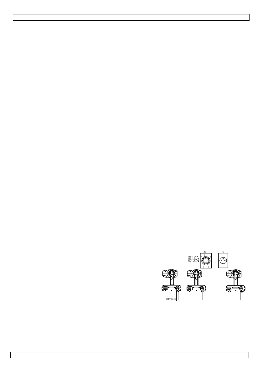
a. Connexion DMX512
Connectez la sortie XLR femelle 3 broches de votre contrôleur avec
l’entrée XLR mâle 3 broches de votre VDP750ST à l’aide du câble
XLR inclus. Plusieurs VDP750ST peuvent être connectés en série.
24.09.2010 ©Velleman nv
10

VDP750ST
glag
Utilisez un câble blindé à double fil conducteur avec des connecteurs XLR d’entrée et de sortie.
b. Connexion DMX-512 avec une terminaison DMX
Une terminaison DMX est à recommander si le câble DMX doit couvrir une grande distance ou s’il est
utilisé dans un environnement avec beaucoup de bruit électrique (ex. un discothèque). La terminaison
prévient la corruption du signal de contrôle numérique par le bruit électrique. Cet appareil est équipé
d'une terminaison DMX incorporée, activé par un interrupteur DIP rouge sur l'appareil. Mettez-le sur ON
si l'appareil est le dernier appareil de la série.
c. Choisir l’adresse de départ du projecteur DMX
Tous les appareils pilotés par un signal DMX demandent une adresse de départ DMX pour assurer que les
appareils corrects réagissent sur les signaux de contrôle. Cette adresse de départ numérique indique le
numéro de canal sur lequel l’appareil écoute le contrôleur DMX. Déterminez cette adresse avec les
interrupteurs DIP de l’appareil.
Vous avez le choix entre une seule adresse de départ pour toute une série d’appareils ou une adresse de
départ par appareil. Dans le cas d’une seule adresse, tous les appareils "écouteront" les mêmes signaux,
sur un seul canal. Tous les appareils seront donc influencés lorsque vous changez les réglages d’un seul
canal. Avec des adresses de départ individuelles, chaque appareil "écoutera" son propre canal. Par
conséquent, un ajustement des réglages d’un canal n’influence que l'appareil sur ce canal.
Canaux DMX:
• Ch 1: vitesse des éclats
• Ch 2: obturateur
! Attention: Ch2 sur 0% et Ch1 de 10% à 85% crée un effet "blinder". CH1 règle le niveau de variation
de l’effet. L’effet ne peut cependant durer que max. 5 secondes, autrement l'ampoule peut être
endommagé. Lorsque CH1 est supérieur à 85%, le stroboscope se met en mode de pilotage par le son.
d. Sélectionner la fonction
Il y a 10 interrupteurs DIP qui déterminent le mode de fonctionnement de l'appareil.
Réglage d'adresse DMX
Mettez l'interrupteur DIP 10 sur ON (en haut). Puis utilisez les premiers 9 interrupteurs pour déterminer
l'adresse. Les 9 interrupteurs ont chacun une valeur différente, qui est toujours 1 de plus que la somme
des valeurs des interrupteurs précédents. Donc: l'interrupteur 1 a comme valeur 1, l'interrupteur 2 a la
valeur 2, interrupteur 3 a la valeur 4, 4 est 8, 5 est 15, 6 est 32, 7 est 64, 8 est 128 et 9 est 256. Prenez
l'adresse désirée et commencez à compter de l'interrupteur 9 au 1 et sélectionnez les valeurs qu'il vous
faut pour y arriver. Mettez les interrupteurs correspondants sur ON. La valeur maximum est 511 (tous 9
interrupteurs sont ON).
Programme d'essai
L'interrupteur 10 doit être OFF (en bas).
Cette fonction vous permet d'activer le programme d'essai automatique (interrupteur 9 OFF) ou de régler
la vitesse let le graduateur vous-même (interrupteur 9 ON).
Pour le programme d'essai automatique, la valeur des premiers 8 interrupteurs n'a pas d'importance, du
moment qu'ils ne sont pas tous ON.
Dans le programme manuel, les interrupteurs 1-4 sont utilisés pour régler la vitesse et les interrupteurs
5-8 servent à régler le graduateur.
Le tableau ci-dessous indique les réglages des interrupteurs pour régler la vitesse et le graduateur (16
niveaux chacun):
niveau ré
e interrupteur DIP niveau réglage interrupteur DIP
0 (lent) OFF – OFF – OFF – OFF 8 OFF – OFF – OFF – ON
1 ON – OFF – OFF – OFF 9 ON – OFF – OFF – ON
2 OFF – ON – OFF – OFF 10 OFF – ON – OFF – ON
3 ON – ON – OFF – OFF 11 ON – ON – OFF – ON
4 OFF – OFF – ON – OFF 12 OFF – OFF – ON – ON
5 ON – OFF – ON – OFF 13 ON – OFF – ON – ON
6 OFF – ON – ON – OFF 14 OFF – ON – ON – ON
7 ON – ON – ON – OFF 15 (vite) ON – ON – ON – ON
24.09.2010 ©Velleman nv
11

p
n
t
m
x
r
b
r
n
e
t
l
a
é
t
o
o
n
b
e
T
e
s
a
e
t
u
a
p
d
e
,
e
t
u
e
s
e
m
n
w
c
é
t
a
c
e
e
e
c
p
e
c
p
é
s
n
a
r
o
N
e
e
o
o
r
t
0
a
5
q
e
a
d
m
m
~
c
m
0
o
f
o
L
e
i
a
z
m
a
p
u
p
h
e
e
x
r
V
c
n
s
t
e
o
R
e
r
e
e
u
r
a
v
v
s
v
W
s
t
c
d
o
a
s
e
u
r
e
d
Pilotage
Cette fo
interrupt
6. En
1. Serrez
2. Le boît
défor
conne
3. Les pa
4. Les câ
l’appa
5. Débra
6. Essuy
solvan
7. Il n’y a
Instal
8. Comm
7. Sp
alimenta
fusible
lampe
DMX in/
dimensio
poids
N’empl
respons
plus d’i
site we
modifié
© DROI
SA Vell
réservé
notice p
préalabl
ar la musique
ction fait que l'
eurs 9 et 10 do
retien
les écrous et l
ier, les lentilles
és, adaptés ou
ions etc.
ties mécaniqu
les d'alimenta
eil.
chez l'appareil
z l'appareil rég
s.
pas de parties
ation").
ndez des pièc
cification
ion
ut
ns
yer cet appar
able de dom
formation co
www.hqpo
s sans notifi
S D’AUTEUR
man est l’aya
. Toute reprod
r quelque proc
écrit de l’ayan
appareil soit pil
ivent être OFF.
s vis et vérifiez
les supports d
bricolés p.ex.
s mobiles ne p
ion ne peuvent
avant de le net
lièrement ave
maintenables
s de rechange
technique
il qu’avec de
ages ou lésio
cernant cet
er.eu. Toutes
ation préalab
nt droit des d
uction, traducti
dé ou sur tout
droit.
VDP7
oté par la musi
qu'ils ne rouill
e montage et l
as de trous ad
uvent pas être
pas être endo
toyer.
un chiffon hu
ar l’utilisateur,
ventuelles che
max. 230VCA
16A
lampe strobos
3-pin femelle/
320 x 136 x 2
4.6kg
s accessoires
s survenus à
rticle et la de
les informati
le.
oits d’auteur
n, copie ou di
support électr
0ST
ue. Les interr
nt pas.
construction
itionnels dans
usées ou boug
magés. Un tec
ide non peluc
à part la lamp
z votre revend
50Hz, 16A ma
opique 750W (
âle XLR
7mm
d’origine. SA
un usage (in
rnière versio
ns présentée
pour cette no
fusion, intégral
nique que se s
pteurs 1-8 doi
ortante ne peu
un support, ne
er de manière i
hnicien qualifié
eux. Evitez l'u
et le fusible (
ur.
.
éf. LAMP750
elleman ne
orrect) de ce
de cette noti
dans cette n
ice. Tous dro
ou partielle,
it est interdite
ent être ON, le
ent pas être
pas déplacer le
rrégulière.
doit entretenir
age d'alcool et
oir "4.
)
era aucunem
appareil. Po
e, visiter not
otice peuvent
its mondiaux
u contenu de c
sans l’accord
s
de
nt
r
e
être
tte
1. In
A los ci
Import
Si tiene
Gracias
usarlo. S
distribui
24.09.201
roducción
dadanos de l
ntes informa
Este símbolo
dañar el medi
doméstica; d
distribuidor o
Respete las l
dudas, conta
or haber comp
i el aparato ha
or.
0
MA
Unión Europ
iones sobre
n este aparat
o ambiente. N
be ir a una em
a la unidad de
yes locales en
te con las au
rado el VDP75
sufrido algún d
UAL DE
a
l medio ambi
o el embalaje
tire este apar
presa especiali
reciclaje local.
elación con el
oridades loca
ST! Lea atent
ño en el trans
12
USUA
nte concerni
ndica que, si ti
to (ni las pilas,
ada en reciclaj
edio ambient
les para resid
mente las inst
orte no lo inst
IO
nte a este pr
a las muestras
si las hubiera)
. Devuelva est
.
os.
ucciones del m
le y póngase e
ducto
inservibles, po
en la basura
e aparato a su
anual antes de
n contacto con
©Vellem
rían
su
n nv

s
s
a
o
p
r
a
n
r
a
ñ
n
a
p
s
s
t
a
a
a
o
z
s
n
e
a
e
l
e
n
m
é
e
e
m
p
o
S
c
r
e
e
a
T
v
e
n
d
0
d
p
d
ó
e
u
e
b
x
p
v
d
v
a
l
e
a
a
a
n
t
p
d
n
e
c
a
5
e
e
o
d
o
t
u
r
a
r
a
a
t
n
c
o
u
o
r
c
d
n
i
e
l
t
s
a
d
o
e
a
u
b
e
C
n
n
a
m
a
a
a
u
c
v
s
s
p
r
m
e
a
u
e
0
a
n
h
v
a
c
a
e
e
r
0
r
o
e
e
y
2. In
truccione
de seguri
ad
VDP7
0ST
• Daños
y su di
• La inst
• No con
aparat
• Este a
tierra.
• Asegú
• No apl
superfi
• Desco
limpia
• Puede
desap
• No mir
• Los da
• Mante
• Si el p
3. No
Véase la
• Este a
sólo e
uso en
• No ha
la vida
• No agi
• Selecci
(véase
ilumin
• Fije el
• Famili
aparat
• Transp
• Por ra
• Utilice
cortoci
anula l
Cuidado dura
con un voltaj
¡No toque el
No exponga
Desconecte e
causados por d
tribuidor no s
lación y el ma
ecte el aparato
llegue a la te
arato pertenec
La conexión el
ese de que la t
ste el cable de
cie afilada. Si e
ecte siempre e
lo. Tire siempr
producirse hu
recerá poco a
e directamente
os causados p
ga el VDP750
nel frontal de
rmas gene
Garantía de s
arato es un ef
tá permitido p
interiores.
ido diseñado p
del VDP750S
e el aparato. E
one un lugar d
"7. Especifica
da.
parato media
rícese con el fu
. La mayoría d
orte el aparato
ones de seguri
sólo el VDP75
rcuitos, quema
a garantía com
te la instalaci
peligroso.
parato durant
ste equipo a ll
cable de alim
escuido de las i
rá responsable
tenimiento de
si ha estado e
peratura ambi
e a la clase de
ctrica debe lle
nsión de red n
alimentación y
s necesario, pi
l aparato si no
del enchufe p
o u olor durant
oco.
a la fuente de
r modificacion
T lejos del alc
ristal está dañ
ales
rvicio y calid
cto de luz para
ra una conexió
ara un uso inin
.
ite usar excesi
montaje dond
ciones "). Res
te un cable de
ncionamiento
e los daños so
en su embalaj
ad, las modifi
ST para las ap
uras, descarg
letamente.
n: puede sufrir
su operación:
via o humedad
ntación de la r
nstrucciones d
de ningún dañ
en ser realizad
puesto a gran
ente.
rotección I. P
arla a cabo un
o sea mayor q
protéjalo cont
a a su distribui
a a usarlo dur
ra desconecta
e la primera pu
uz. Esto puede
s no autorizad
nce de person
do, REEMPLÁC
d Velleman®
uso profesiona
con una fuen
errumpido. Int
va fuerza dura
e el aparato no
ete una distan
seguridad (p.ej
el aparato. Sól
causados por
original.
aciones no aut
licaciones desc
s eléctricas, et
una peligrosa
la caja se calie
.
d antes de abr
seguridad de
u otros proble
os por persona
es cambios de
r lo tanto, es e
écnico cualific
e la tensión in
a posibles dañ
dor reemplazar
nte un largo p
el cable de red
esta en march
causar un ataq
s, no están cu
s no capacitad
ELO.
al final de este
l en una discot
e de corriente
roduzca frecue
te la instalació
esté expuesto
ia de mín. 0.5
. VDLSC8).
personas cual
n uso inadecu
rizadas del ap
itas en este m
. Un uso desa
escarga eléctri
ta!
r la caja.
ste manual in
mas resultante
especializado.
emperatura. E
encial que el a
do.
icada en las es
s causados po
el cable de ali
ríodo de tiemp
, nunca del pro
. Es normal y
e epiléptico.
iertos por la g
as y niños.
manual del us
ca, un teatro,
A de máx. 23
temente una p
y la reparació
polvo, humed
entre la salid
ificadas puede
do.
rato están pro
nual a fin de e
torizado puede
a al tocar los
alidarán su gar
.
pere hasta qu
parato esté pu
ecificaciones.
algún tipo de
entación.
o o antes de
pio cable.
l humo o el olo
rantía.
ario.
tc. El VDP75
Vca/50Hz y pa
ausa para prol
n.
ad y calor extr
de luz y el ár
manejar este
ibidas.
itar p.ej.
causar daños
ables
ntía
el
sto a
ST
a el
ngar
mo
a
24.09.201
0
13
©Vellem
n nv
VDP750ST
4. Instalación
a) Lámpara
• Desconecte el aparato de la red antes de instalar o reemplazar una lámpara.
• Las lámparas llegan a temperaturas de hasta 700°C. Deje que la lámpara se enfríe antes de
reemplazarla. Espere al menos 10 minutos antes de volver a encenderla
• No toque una lámpara halógena con las manos sin protección. Use un paño para reemplazar una
lámpara.
• No use lámparas con más vatios porque éstas generan temperaturas para las que este aparato no ha
sido diseñado.
• Reemplace cada lámpara deformada o defectuosa por una lámpara del mismo tipo (véase "7.
Especificaciones"):
1. Desatornille los 4 tornillos del panel frontal de cristal y quite el panel cuidadosamente.
2. Desatornille los tornillos de los bloques de conexión (a la derecha y a la izquierda) y
desconecte los cables.
3. Quite la lámpara vieja e introduzca la nueva, con los cables al mismo lado que con la lámpara
vieja.
4. Conecte los cables de la nueva lámpara.
5. Vuelva a poner el panel de cristal y apriete los 4 tornillos.
Observación: ¡No use este aparato con la caja abierta!
b) Montaje del aparato
• Respete la directiva EN 60598-2-17 y toda norma nacional antes de instalar el aparato. La instalación
debe ser realizada por un técnico especializado.
• El soporte donde irá el aparato, debe ser capaz de sostener 10 veces el peso de éste durante una hora,
sin que se produzca una deformación de dicho soporte.
• Fije el aparato con un cable de seguridad (seguridad adicional).
• Evite ponerse debajo del aparato durante el montaje, la limpieza, etc. Un técnico especializado debe
revisar el aparato antes de la puesta en marcha. Después, debe revisarlo una vez al año.
• Instale el aparato fuera del alcance de personas no autorizadas y en un lugar con poca gente.
• La instalación de este aparato exige una sólida experiencia práctica: debe poder calcular la carga máx.
del soporte, debe conocer los materiales necesarios para la instalación, etc. De vez en cuando, una
verificación de la estructura y del aparato mismo debe ser llevada a cabo por un técnico especializado.
No intente instalar este aparato si no tiene las cualificaciones requeridas; una instalación incorrecta
puede causar lesiones.
• Ajuste el ángulo de inclinación mediante el soporte de montaje y atornille los tornillos de montaje.
• Quite todo material inflamable en un radio de 50cm alrededor del aparato.
• Pregunte a un electricista cómo hacer la conexión eléctrica.
• Conecte el aparato a la red eléctrica con la conexión de alimentación. Normalmente, no se conectan
efectos luminosos a dimmer packs (reguladores).
• Un experto debe probar la instalación antes de la puesta en marcha.
5. Use
Es posible manejar este aparato en modo manual o en modo DMX. En el modo manual, la velocidad de
los destellos y la función dimmer se ajustan manualmente con los interruptores DIP. En el modo DMX, se
ajustan por 2 canales DMX.
a. Conexión DMX512
Conecte la salida XLR hembra de 3 polos de su controlador con
el cable XLR incluido a la entrada XLR macho de 3 polos del
VDP750ST. Es posible conectar varios VDP750ST en serie.
Utilice un cable XLR blindado con dos hilos conductores con dos
conectores XLR de entrada y de salida.
b. Conexión DMX-512 con una terminación DMX
Se recomienda una terminación si el cable DMX debe cubrir
una gran distancia o si se usa en un medio ambiente con mucho ruido eléctrico (p.ej. una discoteca). La
terminación impide que el ruido eléctrico corrompa la señal de control digital. La terminación DMX no es
más que un conector XLR con una resistencia de 120Ω de polo 2 a polo 3 (véase figura a la izquierda).
Este conector XLR está conectado a la salida XLR del último aparato de la serie.
24.09.2010 ©Velleman nv
14

VDP750ST
c. Determinar la dirección inicial del proyector DMX
Si se usa una señal DMX, cada aparato tiene su propia dirección inicial DMX para asegurar que los
aparatos reaccionen a las señales de control correctas. Esta dirección inicial digital es el primer canal en
el cual el aparato reaccionará a las señales DMX del controlador DMX. Determine esta función con los
interruptores DIP en la parte trasera del aparato.
Es posible elegir entre una sola dirección inicial para toda una serie de aparatos o una dirección inicial por
aparato. Con una sola dirección inicial para una serie de aparatos, todos los aparatos reaccionarán
sincronizadamente a la misma señal. Por lo tanto, cambiar los ajustes de un solo canal afecta a los
ajustes de todos los canales. Con varias direcciones iniciales, cada aparato reaccionará
independientemente. Por lo tanto, cambiar los ajustes de un solo canal sólo afecta al canal en cuestión.
Canales DMX:
• Ch 1: velocidad de los destellos
• Ch 2: shutter
¡Ojo!: Ch2 en 0% y Ch1 del 10% al 85% crea un efecto "blinder" (cegadora). CH1 es el nivel de ajuste
de la intensidad luminosa del efecto. Sin embargo, asegúrese de que el efecto dure máx. 5 segundos, si
no la lámpara podría ser dañada. Si CH1 es superior al 85%, el estroboscopio se pone en el modo de
control por la música.
d. Seleccionar la función
Hay 10 interruptores DIP que determinan el modo de funcionamiento del aparato.
Ajustar la dirección DMX
Coloque el interruptor DIP 10 en ON (hacia arriba). Luego, utilice los primeros 9 interruptores para
determinar la dirección. Los 9 interruptores tienen cada uno un valor diferente, que siempre es 1 más
que la suma de los valores de los interruptores precedentes. Por tanto: el interruptor 1 tiene el valor 1, el
interruptor 2 tiene el valor 2, el interruptor 3 tiene el valor 4, 4 es 8, 5 es 15, 6 es 32, 7 es 64, 8 es 128
y 9 es 256. Seleccione la dirección deseada y empiece a contar del interruptor 9 al interruptor 1 y
seleccione los valores necesarios en camino. Coloque los interruptores correspondientes en ON. El valor
máximo es 511 (todos los 9 interruptores están en ON).
Programa de prueba
Asegúrese de que el interruptor 10 esté en la posición OFF (hacia abajo).
Esta función le permite activar el programa automático de prueba (interruptor 9 OFF) o ajustar la
velocidad y el dimmer usted mismo (interruptor 9 ON).
Para el programa automático de prueba, el valor de los primeros 8 interruptores no es importante,
mientras no estén todos en la posición ON.
En el programa manual, los interruptores 1-4 se utilizan para ajustar la velocidad y los interruptores 5-8
sirven para ajustar el dimmer.
La siguiente lista indica los ajustes de los interruptores para ajustar la velocidad y el dimmer (16 niveles
cada uno):
nivel ajuste del interruptor DIP nivel ajuste del interruptor DIP
0 (lento) OFF – OFF – OFF – OFF 8 OFF – OFF – OFF – ON
1 ON – OFF – OFF – OFF 9 ON – OFF – OFF – ON
2 OFF – ON – OFF – OFF 10 OFF – ON – OFF – ON
3 ON – ON – OFF – OFF 11 ON – ON – OFF – ON
4 OFF – OFF – ON – OFF 12 OFF – OFF – ON – ON
5 ON – OFF – ON – OFF 13 ON – OFF – ON – ON
6 OFF – ON – ON – OFF 14 OFF – ON – ON – ON
7 ON – ON – ON – OFF 15 (rápido) ON – ON – ON – ON
Control por la música
Al utilizar esta función, el aparato está controlado por la música. Los interruptores 1-8 deben estar en
ON, los interruptores 9 y 10 deben estar en OFF.
6. Mantenimiento
1. Apriete bien las tuercas y los tornillos y verifique que no hay señales de oxidación.
2. No modifique la caja, los soportes y las ópticas p.ej. no taladre agujeros adicionales en un soporte o no
modifique las conexiones, etc.
3. Las partes móviles no pueden mostrar ningún rastro de desgaste y deben estar bien equilibradas.
4. No dañe los cables de alimentación. Contacte con un técnico especializado para instalar el aparato.
5. Desconecte el aparato de toda fuente antes de limpiarlo.
6. Limpie el aparato regularmente con un paño húmedo. Evite el uso de alcohol y de disolventes.
7. El usuario no habrá de efectuar el mantenimiento de ninguna pieza salvo las lámparas y los fusibles
(véase "4. Instalación").
8. Contacte con su distribuidor si necesita piezas de recambio.
24.09.2010 ©Velleman nv
15

p
c
r
s
e
o
q
a
C
o
e
n
E
e
w
b
c
h
a
e
D
n
ó
s
r
O
d
r
r
o
n
e
t
o
s
i
d
h
r
u
t
s
e
A
c
u
e
f
o
t
e
E
n
e
d
e
B
s
p
F
f
n
e
e
n
5
5
b
0
n
)
m
c
e
r
u
e
m
p
r
t
o
n
e
d
n
h
c
v
a
u
e
a
r
s
U
t
s
r
h
v
n
e
t
n
m
l
n
m
V
e
M
r
s
u
r
n
c
ö
g
e
n
m
e
a
e
s
e
d
d
e
a
e
7. Es
alimenta
disyunto
lámpara
entrada/
dimensio
peso
Utilice
daños n
este pr
www.h
previo
© DERE
Vellema
derech
guardar
ecificacio
ión
alida DMX
nes
ste aparato s
i lesiones cau
ducto y la ve
power.eu. Se
viso.
HOS DE AUT
n nv dispone
s mundiales r
ste manual de
es
lo con los ac
ados por un
sión más reci
pueden modi
R
e los derech
eservados. Es
l usuario o part
VDP7
máx. 230Vca/
16A
lámpara estro
3 polos, XLR m
320 x 136 x 2
4.6kg
esorios origi
so (indebido
nte de este
icar las espe
s de autor pa
á estrictament
s de ello sin p
0ST
0Hz máx.16A
oscópica 750W
acho y hembra
7mm
ales. Vellema
de este apar
anual del us
ificaciones y
ra este manu
prohibido rep
evio permiso e
(referencia LA
n nv no será
ato. Para má
ario, visite n
l contenido d
l del usuario.
oducir, traduci
crito del derec
P750W)
esponsable d
información
estra página
e este manua
Todos los
, copiar, editar
ho habiente.
obre
web
l sin
y
1. Ei
An alle
Wichtig
Falls Z
Wir beda
Inbetrie
2. Si
• Bei Sc
Garant
• Install
• Nehm
wurde.
• Der Au
sein.
führung
inwohner de
Umweltinfo
Dieses Symb
Produktes na
Einheit (oder
verwendeten
werden. Dies
retourniert w
eifel bestehe
nken uns für d
nahme sorgfäl
herheitsv
Seien Sie vor
lebensgefährl
Berühren Sie
Schützen Sie
Trennen Sie
äden, die durc
ieanspruch. Fü
tion und Wart
n Sie das Gerä
Lassen Sie da
fbau des Gerät
er elektrische
BEDI
Europäische
mationen üb
l auf dem Pro
ch seinem Leb
verwendeten
Batterien müs
e Einheit muss
erden. Respekt
, wenden Sie
n Kauf des VD
ig durch. Über
rschriften
ichtig bei der I
chen elektrisch
das Gerät niem
das Gerät vor
as Gerät vor Ö
Nichtbeachtu
daraus resulti
ng sind einer a
erst in Betrieb
Gerät solange
s entspricht d
nschluss darf
NUNGS
Union
r dieses Prod
ukt oder der V
nszyklus der U
atterien) nicht
en von einer s
an den Händle
ieren Sie die ör
sich für Ents
P750ST! Lese
rüfen Sie, ob T
nstallation: Fas
en Schlag zu v
als während de
euchtigkeit un
fnen vom Netz
g der Bedienu
rende Folgesc
utorisierten Fa
, nachdem es
ausgeschaltet,
r Schutzklasse
ur von einer F
ANLEIT
kt
rpackung zeig
welt Schaden
als unsortierte
ezialisierten Fi
oder ein örtlic
lichen Umwelt
rgungsrichtli
Sie diese Bedi
ransportschäde
sen Sie keine s
rmeiden.
s Betriebes, de
Nässe.
.
gsanleitung ve
äden übernim
hkraft vorbeha
on einem kalte
bis es die Zim
I. Gemäß den
chkraft durchg
NG
an, dass die E
zufügen kann.
Hausmüll; die
ma zwecks Re
es Recycling-U
orschriften.
ien an Ihre
nungsanleitun
n vorliegen.
romführenden
n das Gehäus
rursacht werde
t der Herstelle
ten.
in einen war
ertemperatur
orschriften mu
führt werden.
tsorgung dies
Entsorgen Sie
Einheit oder
ycling entsorgt
nternehmen
rtliche Behör
vor
Kabel an, um
erhitzt sich.
, erlischt der
r keine Haftung
en Raum gebr
rreicht hat.
ss das Gerät g
s
ie
e.
inen
.
cht
erdet
24.09.201
0
16
©Vellem
n nv

VDP750ST
• Achten Sie darauf, dass die Netzleitung nicht gequetscht oder durch scharfe Kanten beschädigt werden
kann. Bei Beschädigungen soll eine Fachkraft das Kabel ersetzen.
• Vergewissern Sie sich, dass die anzuschließende Netzspannung nicht höher ist als die Netzspannung
beschrieben in dieser Bedienungsanleitung
• Trennen Sie das Gerät bei Nichtbenutzung und vor jeder Reinigung vom Netz. Fassen Sie dazu den
Netzstecker an der Grifffläche an und ziehen Sie nie an der Netzleitung.
• Bei der ersten Inbetriebnahme kann es zu Rauch- und Geruchserzeugung kommen. Dies ist normal und
Rauch oder Geruch werden allmählich verschwinden.
• Blicken Sie niemals direkt in die Lichtquelle da bei empfindlichen Menschen epileptische Anfälle
ausgelöst werden können.
• Beachten Sie, dass Schäden, die durch manuelle Veränderungen an diesem Gerät verursacht werden,
nicht unter den Garantieanspruch fallen.
• Halten Sie Kinder und Unbefugte vom Gerät fern.
• Wenn die Glasscheibe an der Vorderseite beschädigt ist, MUSS sie ersetzt werden!
3. Allgemeine Richtlinien
Siehe Velleman® Service- und Qualitätsgarantie am Ende dieser Bedienungsanleitung.
• Dieses Gerät ist eine Lichtsteuerung für den professionellen Einsatz auf Bühnen, in Discotheken,
Theater, usw. Das VDP750ST ist nur für den Anschluss an einen AC-Strom von max. 230Vac/50Hz
zugelassen und wurde ausschließlich zur Verwendung in Innenräumen konzipiert.
• Lichteffekte sind nicht für permanenten Betrieb entworfen worden. Regelmäßiges Ausschalten wird die
Lebensdauer verlängern.
• Vermeiden Sie Erschütterungen. Vermeiden Sie rohe Gewalt während der Installation und Bedienung
des Gerätes.
• Achten Sie bei der Wahl des Installationsortes darauf, dass das Gerät keinem Staub, keiner
Feuchtigkeit und extremen Temperaturen ausgesetzt wird. Sorgen Sie für einen Abstand von minimal
50cm zwischen dem Gerät und einer beleuchteten Oberfläche.
• Sichern Sie das Gerät mit einem geeigneten Sicherheitsfangseil (VDLSC8).
• Nehmen Sie das Gerät erst in Betrieb, nachdem Sie sich mit seinen Funktionen vertraut gemacht
haben. Lassen Sie das Gerät nicht von Personen bedienen, die sich nicht mit dem Gerät auskennen.
Meist ist die Beschädigung des Gerätes das Ergebnis von unfachmännischer Bedienung.
• Verwenden Sie die Originalverpackung, wenn das Gerät transportiert werden soll.
• Eigenmächtige Veränderungen sind aus Sicherheitsgründen verboten.
• Verwenden Sie das Gerät nur für Anwendungen beschrieben in dieser Bedienungsanleitung sonst kann
dies zu Schäden am Produkt führen und erlischt der Garantieanspruch. Jede andere Verwendung ist mit
Gefahren wie Kurzschluss, Brandwunden, elektrischem Schlag, Lampenexplosion, usw. verbunden.
4. Installation
a) Lampe
• Trennen Sie das Gerät vom Netz wenn Sie die Lampe installieren oder reparieren möchten.
• Lampen können eine Temperatur von bis zu 700°C erreichen. Lassen Sie die Lampen deshalb erst
abkühlen.
Schalten Sie die Lampe nicht innerhalb von 10 Minuten nach dem Ausschalten ein.
• Berühren Sie die Halogenlampen nicht mit bloßen Händen. Verwenden Sie ein sauberes Tuch um
Lampen einzusetzen und zu wechseln.
• Setzen Sie keine Lampen mit einer höheren Leistungsangabe ein. Lampen mit einer höheren Leistung
entwickeln höhere Temperaturen, für die das Gerät nicht ausgelegt ist.
• Ersetzen Sie eine verformte oder defekte Lampe durch eine Lampe desselben Typs (siehe “7.
Technische Daten”):
1. Entfernen Sie die 4 Schrauben der Glasscheibe an der Vorderseite und entfernen Sie
vorsichtig die Glasscheibe.
2. Schrauben Sie die linken und rechten Anschlüsse auf & trennen Sie die Kabel.
3. Entfernen Sie die Lampe und setzen Sie eine neue ein.
4. Verbinden Sie die Kabel der neuen Lampe.
5. Bringen Sie die Glasscheibe erneut an und schrauben Sie die 4 Schrauben wieder fest.
Wichtig: verwenden Sie das Gerät nicht wenn die Glasscheibe entfernt ist.
24.09.2010 ©Velleman nv
17

VDP750ST
b) Das Gerät montierten
• Betrachten Sie erst den Inhalt der Richtlinie EN 60598-2-17 und die (eventuellen) nationalen Normen
ehe Sie das Gerät installieren. Die Installation darf nur von einer Fachkraft durchgeführt werden.
• Die Tragkonstruktion für das Gerät muss während 1 Stunde 10 x das erforderliche Gewicht tragen
können, ohne dass die Konstruktion sich dadurch verformt.
• Das Gerät muss ebenfalls ein geeignetes Sicherheitsfangseil haben.
• Achten Sie bei der Montage, beim Abbau und bei der Durchführung von Servicearbeiten darauf, dass
der Bereich unterhalb des Montageortes abgesperrt ist. Stehen Sie niemals direkt unter dem Gerät.
Lassen Sie die Installation vor Inbetriebnahme von einer Fachkraft kontrollieren. Lassen Sie das Gerät
auch 1 x pro Jahr nachsehen.
• Montieren Sie das Gerät an einem Ort, wo niemand es berühren kann und wo wenige Leute
vorübergehen.
• Eine gründliche praktische Erfahrung ist für die Installation des Gerätes notwendig: Sie müssen die
max. Belastung der Tragkonstruktion berechnen können, wissen welches Konstruktionsmaterial Sie
verwenden dürfen. Außerdem müssen Sie das verwendete Material und das Gerät regelmäßig
nachsehen lassen. Montieren Sie das Gerät nie selber wenn Sie damit keine Erfahrung haben. Eine
schlechte Montage kann Verletzungen verursachen.
• Regeln Sie gewünschte Neigung über den Montagebügel und die Schrauben.
• Entfernen Sie alle entflammbaren Materialien in einem Abstand von 50cm.
• Der elektrische Anschluss darf nur von einer Fachkraft durchgeführt werden.
• Schließen Sie das Gerät über den Stecker an das Netz an. Lichteffekte sollten im Allgemeinen nicht
über Dimmerpacks geschaltet werden.
• Die Installation muss vor Inbetriebnahme von einem Experten genehmigt werden.
5. Gebrauch
Das Gerät kann in manuellem oder DMX-Modus bedient werden. Sie können die Blitzgeschwindigkeit und
Dimmerfunktion manuell über die DIP-Schalter einstellen. Im DMX-Modus werden Geschwindigkeit und
Dimmerfunktion durch zwei Kanäle bestimmt.
a. DMX-512-Anschlüsse
Verbinden Sie das mitgelieferte XLR-Kabel mit der 3poligen XLR-Ausgangsbuchse des Steuergerätes und die
andere Seite mit dem 3-poligen XLR-Eingang des
VDP750ST. Verschiedene VDP750STs können seriell
miteinander verbunden werden. Die Verbindungskabel
sollten ein zweiadriges, abgeschirmtes Kabel mit XLREingangs- und Ausgangsanschlüssen sein. Siehe Abbildung
rechts.
b. DMX-512-Kette mit Abschlusswiderstand
Ein DMX-Abschlusswiderstand ist empfehlenswert für Installationen, bei denen das DMX-Kabel lang ist
oder in einer Umgebung mit vielem elektrischem Rauschen (z.B. Diskos). Der Abschlusswiderstand
verhindert Störung des digitalen Steuersignals durch elektrisches Rauschen. Dieses Gerät hat einen
eingebauten DMX-Abschlusswiderstand, der mittels des roten DIP-Schalters auf dem Gerät aktiviert wird.
Schalten Sie ihn in die ON-Position wenn das Gerät das letzte in der Kette ist.
c. Die Startadresse für den DMX-Projektor wählen
Alle DMX-gesteuerten Geräte brauchen eine digitale Startadresse, sodass das richtige Gerät auf die
Signale reagieren kann. Diese digitale Startadresse ist die Kanalnummer, von der das Gerät die Befehle
der DMX-Steuerung empfängt und ausführt. Stellen Sie die richtige Kanalnummer mit den DIP-Schaltern
auf dem Gerät ein.
Sie können dieselbe Startadresse für eine ganze Gruppe von Geräten verwenden oder eine separate
Startadresse für jedes Gerät eingeben.
Wenn alle Geräte dieselbe Startadresse haben, werden sie auf einem spezifischen Kanal das Steuersignal
empfangen. Mit anderen Worten, wenn Sie die Einstellungen von einem Kanal ändern, werden alle Geräte
zur gleichen Zeit beeinflusst. Wenn Sie verschiedene Adressen einstellen, wird jedes Gerät auf einem
anderen Kanal Signale empfangen. Wenn Sie die Einstellungen ändern, wird nur das besagte Gerät
beeinflusst.
24.09.2010 ©Velleman nv
18

VDP750ST
DMX-Kanäle
• Kanal 1: Stroboskopgeschwindigkeit
• Kanal 2: Stroboksopdimmer
Warnung! Ch2 auf 0% und Ch1 von 10% bis 85% kreiert einen Blinder-Effekt. CH1 ist das Dimniveau
des Effektes. Beachten Sie, dass dieser Effekt nicht mehr als max. 5 Sekunden dauert, sonst kann die
Lampe beschädigt werden. Stellen Sie CH1 höher als 85%, so funktioniert das Stroboskop im
musikgesteuerten Modus.
d. Funktionsauswahl
Es gibt 10 DIP-Schalter; wie Sie eingestellt sind, bestimmt den Modus des Gerätes.
DMX-Adressen
Stellen Sie DIP-Schalter 10 auf ON (up). Verwenden Sie jetzt die ersten 9 DIP-Schalter um die Adressen
zu bestimmen. Die 9 Schalter haben jeweils einen anderen Wert, immer die Summe der vorigen Schalter
+ 1. Das bedeutet, dass Schalter 1 Wert 1 hat, Schalter 2 hat Wert 2, Schalter 3 hat Wert 4, 4 ist 8, 5 ist
15, 6 ist 32, 7 ist 64, 8 ist 128 and 9 ist 256. Nehmen Sie die Adresse, die Sie dem Gerät zuweisen
wollen, und addieren Sie von Schalter 9 bis 1, wählen Sie währenddessen die erforderlichen Werte und
stellen Sie die entsprechenden Schalter auf ON. Der Maximalwert ist 511 (alle 9 Schalter sind 'ON').
Testprogramm
Schalter 10 muss auf 'OFF' stehen (nach unten).
Mit dieser Funktion können Sie das automatische Testprogramm (Schalter 9 OFF) ablaufen lassen oder
die Geschwindigkeit und Dimmerfunktionen selbst einstellen (Schalter 9 ON).
Für das automatische Testprogramm ist der Wert der ersten 8 Schalter nicht so wichtig, solange sie nicht
alle auf ON stehen.
Im manuellen Programm werden Schalter 1-4 verwendet um die Geschwindigkeit einzustellen und
Schalter 5-8 werden für die Dimmerfunktion benutzt.
In der Tabelle unten finden Sie wie Sie die Schalter stellen müssen um Geschwindigkeit und
Dimmerfunktion einzustellen (jeweils 16 Stufen):
Stufe DIP-Schalter Stufe DIP-Schalter
0 (slow) OFF – OFF – OFF – OFF 8 OFF – OFF – OFF – ON
1 ON – OFF – OFF – OFF 9 ON – OFF – OFF – ON
2 OFF – ON – OFF – OFF 10 OFF – ON – OFF – ON
3 ON – ON – OFF – OFF 11 ON – ON – OFF – ON
4 OFF – OFF – ON – OFF 12 OFF – OFF – ON – ON
5 ON – OFF – ON – OFF 13 ON – OFF – ON – ON
6 OFF – ON – ON – OFF 14 OFF – ON – ON – ON
7 ON – ON – ON – OFF 15 (fast) ON – ON – ON – ON
Musiksteuerung
Diese Funktion stellt das Gerät auf 'musikgesteuert' ein. Schalter 1-8 müssen auf ON stehen, Schalter 9
und 10 müssen OFF sein.
6. Wartung
1. Verwendete Schrauben müssen fest angespannt werden und dürfen keine Rostspuren zeigen.
2. Das Gehäuse, die Linsen, die Montagebügel und der Montageort (z.B. Decke oder Gebinde) dürfen nicht
angepasst werden, z.B. bohren Sie keine zusätzlichen Löcher in Montagebügeln, verändern Sie die
Anschlüsse nicht, usw.
3. Mechanisch bewegende Teile dürfen keine Spuren von Abnutzung aufweisen und müssen gut
ausgeglichen sein.
4. Die Versorgungskabel dürfen nicht beschädigt sein. Lassen Sie das Gerät durch einen qualifizierten
Techniker installieren.
5. Trennen Sie das Gerät vor Wartungsarbeiten vom Netz.
6. Reinigen Sie das Gerät regelmäßig mit einem feuchten, flusenfreien Tuch. Verwenden Sie keinen
Alkohol oder Lösungsmittel.
7. Außer der Lampe, gibt es keine wartbaren Teile (siehe “4. Installation”).
8. Bestellen Sie Ersatzteile bei Ihrem Vertragshändler.
24.09.2010 ©Velleman nv
19

VDP750ST
7. Technische Daten
Stromversorgung max. 230VAC~50Hz, 16A max.
Leistungsschalter 16A
Lampe 750W Stroboskoplampe (Artikelnummer LAMP750W)
DMX EIN/AUS 3-polige(r) XLR-Buchse/Stecker
Abmessungen 320 x 136 x 207mm
Gesamtgewicht 4.6kg
Verwenden Sie dieses Gerät nur mit originellen Zubehörteilen. Velleman nv übernimmt keine
Haftung für Schaden oder Verletzungen bei (falscher) Anwendung dieses Gerätes. Für mehr
Informationen zu diesem Produkt und die neueste Version dieser Bedienungsanleitung, siehe
www.hqpower.eu. Alle Änderungen ohne vorherige Ankündigung vorbehalten.
© URHEBERRECHT
Velleman nv besitzt das Urheberrecht für diese Bedienungsanleitung. Alle weltweiten Rechte
vorbehalten. Ohne vorherige schriftliche Genehmigung des Urhebers ist es nicht gestattet, diese
Bedienungsanleitung ganz oder in Teilen zu reproduzieren, zu kopieren, zu übersetzen, zu bearbeiten
oder zu speichern.
24.09.2010 ©Velleman nv
20

®
Velleman
Service and Quality Warranty
®
Velleman
has over 35 years of experience in the electronics world
and distributes its products in more than 85 countries.
All our products fulfil strict quality requirements and legal
stipulations in the EU. In order to ensure the quality, our products
regularly go through an extra quality check, both by an internal
quality department and by specialized external organisations. If, all
precautionary measures notwithstanding, problems should occur,
please make appeal to our warranty (see guarantee conditions).
General Warranty Conditions Concerning Consumer Products
(for EU):
• All consumer products are subject to a 24-month warranty on
production flaws and defective material as from the original date of
purchase.
®
• Velleman
article, or to refund the retail value totally or partially when the
complaint is valid and a free repair or replacement of the article is
impossible, or if the expenses are out of proportion.
You will be delivered a replacing article or a refund at the value of
100% of the purchase price in case of a flaw occurred in the first
year after the date of purchase and delivery, or a replacing article at
50% of the purchase price or a refund at the value of 50% of the
retail value in case of a flaw occurred in the second year after the
date of purchase and delivery.
• Not covered by warranty:
- all direct or indirect damage caused after delivery to the article
(e.g. by oxidation, shocks, falls, dust, dirt, humidity...), and by the
article, as well as its contents (e.g. data loss), compensation for loss
of profits;
- frequently replaced consumable goods, parts or accessories such as
batteries, lamps, rubber parts, drive belts... (unlimited list);
- flaws resulting from fire, water damage, lightning, accident, natural
disaster, etc.;
- flaws caused deliberately, negligently or resulting from improper
handling, negligent maintenance, abusive use or use contrary to the
manufacturer’s instructions;
- damage caused by a commercial, professional or collective use of
the article (the warranty validity will be reduced to six (6) months
when the article is used professionally);
- damage resulting from an inappropriate packing and shipping of
the article;
- all damage caused by modification, repair or alteration performed
by a third party without written permission by Velleman
• Articles to be repaired must be delivered to your Velleman
solidly packed (preferably in the original packaging), and be
completed with the original receipt of purchase and a clear flaw
description.
• Hint: In order to save on cost and time, please reread the manual
and check if the flaw is caused by obvious causes prior to presenting
the article for repair. Note that returning a non-defective article can
also involve handling costs.
• Repairs occurring after warranty expiration are subject to shipping
costs.
• The above conditions are without prejudice to all commercial
warranties.
The above enumeration is subject to modification according to the
article (see article’s manual).
Velleman
Velleman
verdeelt in meer dan 85 landen.
Al onze producten beantwoorden aan strikte kwaliteitseisen en aan
de wettelijke bepalingen geldig in de EU. Om de kwaliteit te
waarborgen, ondergaan onze producten op regelmatige tijdstippen
een extra kwaliteitscontrole, zowel door onze eigen kwaliteitsafdeling
als door externe gespeci aliseerde organisaties. Mocht er ondanks
deze voorzorgen toch een probleem optreden, dan kunt u steeds een
beroep doen op onze waarborg (zie waarborgvoorwaarden).
Algemene waarborgvoorwaarden consumentengoederen
(voor Europese Unie):
• Op alle consumentengoederen geldt een garantieperiode van 24
maanden op productie- en materiaalfouten en dit vanaf de
oorspronkelijke aankoopdatum.
• Indien de klacht gegrond is en een gratis reparatie of vervanging
van een artikel onmogelijk is of indien de kosten hiervoor buiten
verhouding zijn, kan Velleman
te vervangen door een gelijkwaardig artikel of de aankoopsom van
het artikel gedeeltelijk of volledig terug te betalen. In dat geval krijgt
u een vervangend product of terugbetaling ter waarde van 100% van
de aankoopsom bij ontdekking van een gebrek tot één jaar na
aankoop en levering, of een vervangend product tegen 50% van de
kostprijs of terugbetaling van 50% bij ontdekking na één jaar tot 2
jaar.
• Valt niet onder waarborg:
- alle rechtstreekse of onrechtstreekse schade na de levering
veroorzaakt aan het toestel (bv. door oxidatie, schokken, val, stof,
can decide to replace an article with an equivalent
®
service- en kwaliteitsgarantie
®
heeft ruim 35 jaar ervaring in de elektronicawereld en
®
.
®
dealer,
®
beslissen het desbetreffende artikel
vuil, vocht...), en door het toestel, alsook zijn inhoud (bv. verlies van
data), vergoeding voor eventuele winstderving.
- verbruiksgoederen, onderdelen of hulpstukken die regelmatig
dienen te worden vervangen, zoals bv. batterijen, lampen, rubberen
onderdelen, aandrijfriemen... (onbeperkte lijst).
- defecten ten gevolge van brand, waterschade, bliksem, ongevallen,
natuurrampen, enz.
- defecten veroorzaakt door opzet, nalatigheid of door een
onoordeelkundige behandeling, slecht onderhoud of abnormaal
gebruik of gebruik van het toestel strijdig met de voorschriften van
de fabrikant.
- schade ten gevolge van een commercieel, professioneel of collectief
gebruik van het apparaat (bij professioneel gebruik wordt de
garantieperiode herleid tot 6 maand).
- schade veroorzaakt door onvoldoende bescherming bij transport
van het apparaat.
- alle schade door wijzigingen, reparaties of modificaties uitgevoerd
door derden zonder toestemming van Velleman
• Toestellen dienen ter reparatie aangeboden te worden bij uw
®
-verdeler. Het toestel dient vergezeld te zijn van het
Velleman
oorspronkelijke aankoopbewijs. Zorg voor een degelijke verpakking
(bij voorkeur de originele verpakking) en voeg een duidelijke
foutomschrijving bij.
• Tip: alvorens het toestel voor reparatie aan te bieden, kijk nog
eens na of er geen voor de hand liggende reden is waarom het
toestel niet naar behoren werkt (zie handleiding). Op deze wijze kunt
u kosten en tijd besparen. Denk eraan dat er ook voor niet-defecte
toestellen een kost voor controle aangerekend kan worden.
• Bij reparaties buiten de waarborgperiode zullen transportkosten
aangerekend worden.
• Elke commerciële garantie laat deze rechten onverminderd.
Bovenstaande opsomming kan eventueel aangepast worden
naargelang de aard van het product (zie handleiding van het
betreffende product).
Garantie de service et de qualité Velleman
®
jouit d’une expérience de plus de 35 ans dans le monde
Velleman
de l’électronique avec une distribution dans plus de 85 pays.
Tous nos produits répondent à des exigences de qualité rigoureuses
et à des dispositions légales en vigueur dans l’UE. Afin de garantir la
qualité, nous soumettons régulièrement nos produits à des contrôles
de qualité supplémentaires, tant par notre propre service qualité que
par un service qualité externe. Dans le cas improbable d’un défaut
malgré toutes les précautions, il est possible d’invoquer notre
garantie (voir les conditions de garantie).
Conditions générales concernant la garantie sur les produits
grand public (pour l’UE) :
• tout produit grand public est garanti 24 mois contre tout vice de
production ou de matériaux à dater du jour d’acquisition effective ;
• si la plainte est justifiée et que la réparation ou le remplacement
d’un article est jugé impossible, ou lorsque les coûts s’avèrent
disproportionnés, Velleman
un article équivalent ou à rembourser la totalité ou une partie du prix
d’achat. Le cas échéant, il vous sera consenti un article de
remplacement ou le remboursement complet du prix d’achat lors
d’un défaut dans un délai de 1 an après l’achat et la livraison, ou un
article de remplacement moyennant 50% du prix d’achat ou le
remboursement de 50% du prix d’achat lors d’un défaut après 1 à 2
ans.
• sont par conséquent exclus :
- tout dommage direct ou indirect survenu à l’article après livraison
(p.ex. dommage lié à l’oxydation, choc, chute, poussière, sable,
impureté…) et provoqué par l’appareil, ainsi que son contenu (p.ex.
perte de données) et une indemnisation éventuelle pour perte de
revenus ;
- tout bien de consommation ou accessoire, ou pièce qui nécessite un
remplacement régulier comme p.ex. piles, ampoules, pièces en
caoutchouc, courroies… (liste illimitée) ;
- tout dommage qui résulte d’un incendie, de la foudre, d’un
accident, d’une catastrophe naturelle, etc. ;
- tout dommage provoqué par une négligence, volontaire ou non,
une utilisation ou un entretien incorrect, ou une utilisation de
l’appareil contraire aux prescriptions du fabricant ;
- tout dommage à cause d’une utilisation commerciale,
professionnelle ou collective de l’appareil (la période de garantie sera
réduite à 6 mois lors d’une utilisation professionnelle) ;
- tout dommage à l’appareil qui résulte d’une utilisation incorrecte ou
différente que celle pour laquelle il a été initialement prévu comme
décrit dans la notice ;
- tout dommage engendré par un retour de l’appareil emballé dans
un conditionnement non ou insuffisamment protégé ;
- toute réparation ou modification effectuée par une tierce personne
sans l’autorisation explicite de SA Velleman
- frais de transport de et vers Velleman
couvert sous la garantie.
• toute réparation sera fournie par l’endroit de l’achat. L’appareil doit
nécessairement être accompagné du bon d’achat d’origine et être
®
s’autorise à remplacer ledit article par
®
.
®
®
;
®
si l’appareil n’est plus

dûment conditionné (de préférence dans l’emballage d’origine avec
mention du défaut) ;
• conseil : il est conseillé de consulter la notice et de contrôler
câbles, piles, etc. avant de retourner l’appareil. Un appareil retourné
jugé défectueux qui s’avère en bon état de marche pourra faire
l’objet d’une note de frais à charge du consommateur ;
• une réparation effectuée en-dehors de la période de garantie fera
l’objet de frais de transport ;
• toute garantie commerciale ne porte pas atteinte aux conditions
susmentionnées.
La liste susmentionnée peut être sujette à une
complémentation selon le type de l’article et être mentionnée
dans la notice d’emploi.
Garantía de servicio y calidad Velleman
®
disfruta de una experiencia de más de 35 años en el
Velleman
mundo de la electrónica con una distribución en más de 85 países.
Todos nuestros productos responden a normas de calidad rigurosas y
disposiciones legales vigentes en la UE. Para garantizar la calidad,
sometimos nuestros productos regularmente a controles de calidad
adicionales, tanto por nuestro propio servicio de calidad como por un
servicio de calidad externo. En el caso improbable de que surgieran
problemas a pesar de todas las precauciones, es posible apelar a
nuestra garantía (véase las condiciones de garantía).
Condiciones generales referentes a la garantía sobre
productos de venta al público (para la Unión Europea):
• Todos los productos de venta al público tienen un período de
garantía de 24 meses contra errores de producción o errores en
materiales desde la adquisición original;
• Si la queja está fundada y si la reparación o la sustitución de un
artículo es imposible, o si los gastos son desproporcionados,
®
autoriza reemplazar el artículo por un artículo equivalente
Velleman
o reembolsar la totalidad o una parte del precio de compra. En este
caso, recibirá un artículo de recambio o el reembolso completo del
precio de compra al descubrir un defecto hasta un año después de la
compra y la entrega, o un artículo de recambio al 50% del precio de
compra o la sustitución de un 50% del precio de compra al descubrir
un defecto después de 1 a 2 años.
• Por consiguiente, están excluidos entre otras cosas:
- todos los daños causados directamente o indirectamente al aparato
y su contenido después de la entrega (p.ej. por oxidación, choques,
caída,...) y causados por el aparato, al igual que el contenido (p.ej.
pérdida de datos) y una indemnización eventual para falta de
ganancias;
- partes o accesorios que deban ser reemplazados regularmente,
como por ejemplo baterías, lámparas, partes de goma, ... (lista
ilimitada);
- defectos causados por un incendio, daños causados por el agua,
rayos, accidentes, catástrofes naturales, etc.;
- defectos causados a conciencia , descuido o por malos tratos, un
mantenimiento inapropiado o un uso anormal del aparato contrario a
las instrucciones del fabricante;
- daños causados por un uso comercial, profesional o colectivo del
aparato (el período de garantía se reducirá a 6 meses con uso
profesional);
- daños causados por un uso incorrecto o un uso ajeno al que está
previsto el producto inicialmente como está descrito en el manual del
usuario;
- daños causados por una protección insuficiente al transportar el
aparato.
- daños causados por reparaciones o modificaciones efectuadas por
una tercera persona sin la autorización explicita de SA Velleman
- se calcula gastos de transporte de y a Velleman
no está cubierto por la garantía.
• Cualquier reparación se efectuará por el lugar de compra. Devuelva
el aparato con la factura de compra original y transpórtelo en un
embalaje sólido (preferentemente el embalaje original). Incluya
también una buena descripción del defecto;
• Consejo: Lea el manual del usuario y controle los cables, las pilas,
etc. antes de devolver el aparato. Si no se encuentra un defecto en
el artículo los gastos podrían correr a cargo del cliente;
• Los gastos de transporte correrán a carga del cliente para una
reparación efectuada fuera del periodo de garantía.
• Cualquier gesto comercial no disminuye estos derechos.
La lista previamente mencionada puede ser adaptada según el
tipo de artículo (véase el manual del usuario del artículo en
cuestión)
®
®
si el aparato ya
®
;
®
Service- und Qualitätsgarantie
Velleman
®
Velleman
hat gut 35 Jahre Erfahrung in der Elektronikwelt und
vertreibt seine Produkte in über 85 Ländern.
Alle Produkte entsprechen den strengen Qualitätsforderungen und
gesetzlichen Anforderungen in der EU. Um die Qualität zu
gewährleisten werden unsere Produkte regelmäßig einer zusätzlichen
Qualitätskontrolle unterworfen, sowohl von unserer eigenen
Qualitätsabteilung als auch von externen spezialisierten
Organisationen. Sollten, trotz aller Vorsichtsmaßnahmen, Probleme
auftreten, nehmen Sie bitte die Garantie in Anspruch (siehe
Garantiebedingungen).
Allgemeine Garantiebedingungen in Bezug auf Konsumgüter
(für die Europäische Union):
• Alle Produkte haben für Material- oder Herstellungsfehler eine
Garantieperiode von 24 Monaten ab Verkaufsdatum.
• Wenn die Klage berechtigt ist und falls eine kostenlose Reparatur
oder ein Austausch des Gerätes unmöglicht ist, oder wenn die Kosten
dafür unverhältnismäßig sind, kann Velleman
entscheiden, dieses Produkt durch ein gleiches Produkt zu ersetzen
oder die Kaufsumme ganz oder teilweise zurückzuzahlen. In diesem
Fall erhalten Sie ein Ersatzprodukt oder eine Rückzahlung im Werte
von 100% der Kaufsumme im Falle eines Defektes bis zu 1 Jahr nach
Kauf oder Lieferung, oder Sie bekommen ein Ersatzprodukt im Werte
von 50% der Kaufsumme oder eine Rückzahlung im Werte von 50 %
im Falle eines Defektes i m zweiten Jahr.
• Von der Garantie ausgeschlossen sind:
- alle direkten oder indirekten Schäden, die nach Lieferung am Gerät
und durch das Gerät verursacht werden (z.B. Oxidation, Stöße, Fall,
Staub, Schmutz, Feuchtigkeit, ...), sowie auch der Inhalt (z.B.
Datenverlust), Entschädigung für eventuellen Gewinnausfall.
- Verbrauchsgüter, Teile oder Zubehörteile, die regelmäßig
ausgewechselt werden, wie z.B. Batterien, Lampen, Gummiteile,
Treibriemen, usw. (unbeschränkte Liste).
- Schäden verursacht durch Brandschaden, Wasserschaden, Blitz,
Unfälle, Naturkatastrophen, usw.
- Schäden verursacht durch absichtliche, nachlässige oder
unsachgemäße Anwendung, schlechte Wartung, zweckentfremdete
Anwendung oder Nichtbeachtung von Benutzerhinweisen in der
Bedienungsanleitung.
- Schäden infolge einer kommerziellen, professionellen oder
kollektiven Anwendung des Gerätes (bei gewerblicher Anwendung
wird die Garantieperiode auf 6 Monate zurückgeführt).
- Schäden verursacht durch eine unsachgemäße Verpackung und
unsachgemäßen Transport des Gerätes.
- alle Schäden verursacht durch unautorisierte Änderungen,
Reparaturen oder Modifikationen, die von einem Dritten ohne
Erlaubnis von Velleman
• Im Fall einer Reparatur, wenden Sie sich an Ihren Velleman
Verteiler. Legen Sie das Produkt ordnungsgemäß verpackt
(vorzugsweise die Originalverpackung) und mit dem OriginalKaufbeleg vor. Fügen Sie eine deutliche Fehlerumschreibung hinzu.
• Hinweis: Um Kosten und Zeit zu sparen, lesen Sie die
Bedienungsanleitung nochmals und überprüfen Sie, ob es keinen auf
de Hand liegenden Grund gibt, ehe Sie das Gerät zur Reparatur
zurückschicken. Stellt sich bei der Überprüfung des Geräts heraus,
dass kein Geräteschaden vorliegt, könnte dem Kunden eine
Untersuchungspauschale berechnet.
• Für Reparaturen nach Ablauf der Garantiefrist werden
Transportkosten berechnet.
• Jede kommerzielle Garantie lässt diese Rechte unberührt.
Die oben stehende Aufzählung kann eventuell angepasst
werden gemäß der Art des Produktes (siehe
Bedienungsanleitung des Gerätes).
®
vorgenommen werden.
®
sich darüber
®
-
 Loading...