


DVM13MFC2
2.4GHz HIGH-RESOLUTION FREQUENCY COUNTER DIGITALE TELLER MET HOGE RESOLUTIE 2.4GHz COMPTEUR DE FRÉQUENCE HAUTE RÉSOLUTION 2.4GHz CONTADOR DE FRECUENCIA DE ALTA RESOLUCIÓN 2.4GHz 2.4GHz FREQUENZZÄHLER MIT HOHER AUFLÖSUNG FREQUENZIMETRO 2.4GHz AD ALTA RISOLUZIONE
USER MANUAL
GEBRUIKERSHANDLEIDING
NOTICE D’EMPLOI
MANUAL DEL USUARIO
BEDIENUNGSANLEITUNG
ISTRUZIONI
DVM13MFC2 |
- 2 - |
VELLEMAN |

DVM13MFC2 – 2.4GHz HIGH-RESOLUTION FREQUENCY COUNTER
1. Introduction & Features
To all residents of the European Union
Important environmental information about this product
This symbol on the device or the package indicates that disposal of the device after its lifecycle could harm the environment.
Do not dispose of the unit (or batteries) as unsorted municipal waste; it should be taken to a specialised company for recycling.
This device should be returned to your distributor or to a local recycling service. Respect the local environmental rules.
If in doubt, contact your local waste disposal authorities.
Thank you for buying the DVM13MFC2! Please read the manual thoroughly before bringing this device into service. If the device was damaged in transit, don't install or use it and contact your dealer.
The DVM13MFC2 is a high-resolution, multifunction intelligent frequency counter based on a microprocessor. The features include: frequency, period measuring, 3-step function selection, working state, unit and 8-digit LED display.
2. Description
1. |
port channel A |
10.CONFIRM key |
2. |
port channel B |
11.FUNCTION key |
3. |
frequency indication LED |
12.ATT key |
4. |
period indication LED |
13.AC/DC COUPLING key |
5. |
LED display |
14.GATE TIME knob |
6. |
kHz/s indication LED |
15.POWER switch |
7. |
MHz/ms indication LED |
16.220V/110V switch |
8. |
RESET key |
17.power jack and fuse |
9. PERIOD key
3.The Keys
Make sure to connect your DVM13MFC2 to an AC 220V/110V (± 10%) mains socket. Maximum consumption is 5W. Switch on your device 20 minutes before measuring. This preheats the unit and the crystal oscillator to ensure accurate readings and stability.
FUNCTION key (3 steps)
Step 1: 50MHz ~ 2.4GHz range, input from channel B, measurement unit indication in MHz/ms.
DVM13MFC2 |
- 3 - |
VELLEMAN |
Step 2: 2MHz ~ 50MHz range, input from channel A, measurement unit indication in MHz/ms. Step 3: 0.01Hz ~ 2MHz range, input from channel A, measurement unit indication in KHz/s.
PERIOD key
Press this key to enter the period measurement mode.
CONFIRM key
Press this key, the instrument will start working according the preset mode.
AC/DC COUPLING key
Position this button in the down position for DC measurements. Position this button in the up position for AC measurements.
RESET key
Press this key to reset your DVR13MFC2.
ATT key
Position this button in the down position for a measurement attenuated by 20dB. Position this button in the up position for a non-attenuated measurement.
4. Operation
Make sure to match the voltage from the local mains with the voltage on your DVM13MFC2. Check the 220V/110V switch at the back of the device.
Connect the power cord to a power outlet (AC 220V/110V, 50Hz or 60Hz) and switch on your DVR13MFC2. Allow the unit to warm up for 20 minutes.
Frequency Measurement
1.Select channel A or channel B (depending on the range being measured) and connect it to the signal source by means of the cable.
2.Press the AC/DC COUPLING key if the frequency of the signal to be measured is less than 100Hz.
3.If the input signal is high, press the ATT key to ensure that the DVR13MFC2 will measure an attenuated signal.
4.When the FUNCTION key is pressed, the last digit display value is the current selection step.
The frequency measurement has only 3 steps.
5.Complete steps 1 to 3 and press the CONFIRM key. The DVR13MFC2 displays the measurement results.
6.Adjust the gate time.
7.When measuring a 100Hz signal, the device will automatically start measuring the period and display the measuring results.
Period Measurement
Press the PERIOD key. The device will start measuring the period and display the test results.
5. Examples
∙Connect the DVM13MFC2 to the mains (110V/220V AC).
∙Switch on the device with the ON button and preheat it for 20 minutes.
∙Connect the test cable with the input port on the front panel. Select channel A or B according to the frequency range.
∙Select the proper function and gate time. The shorter the gate time, the faster the frequency measurement but the lower the resolution. The longer the gate time, the slower the frequency measurement but the higher the resolution.
∙Press PERIOD to measure the period. Confirm by pressing the CONFIRM key. The device starts measuring.
DVM13MFC2 |
- 4 - |
VELLEMAN |
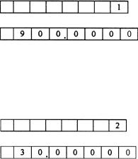
a. Example 1: Measuring an analogue handset
Connect the test cable with the input from channel B and set the FUNCTION key to the 1-step position. Select the gate time (adjust manually from 100 msec to 10 sec). The LED display will read:
1-step
900MHz
b. Example 2: Measuring a 30Mhz intercom emission frequency
Set the FUNCTION to the 2-step position and select the gate time (adjust manually from 100 msec to 10 sec). The LED display will read:
2-step
30MHz
c. Example 3: Measuring a self-oscillating frequency (e.g. from a telephone, intercom etc.)
Set the FUNCTION key to the 2-step position. Connect one end of a cable with 5pF capacitance to the red clamp; use the other end to measure the frequency by touching the contact point.
6. Warnings
∙When measuring a high-voltage or strong RF signal, make sure that the cables are in series and have a large capacitance to avoid damage.
∙Press the RESET button once to reset the device or turn off the device in case the device is not working appropriately.
∙When there is no input signal, the display may not necessarily read “0”. This is absolutely normal and does not affect the measurements or the accuracy.
∙Do not expose the device to extreme temperatures, humidity, dirt, dust etc. Do not open the device to avoid lethal electroshocks.
∙A strong interference will reduce the sensitivity when measuring.
7. Technical Specifications
Channel A (0.01Hz ~ 50MHz)
Frequency Range
Sensitivity
Impedance
Attenuator
Max. Safety Voltage Channel B (50MHz ~ 2.4GHz)
Frequency Range Sensitivity
Coupling
Impedance
Max. Safety Voltage
DC couple 0.01Hz to 100Hz AC couple 100Hz to 50MHz
AC: 100Hz ~ 50MHz < 80m Vrms DC: 0.01Hz ~ 1Hz ≤ 500m Vp-p 1Hz ~ 100Hz ≤ 80m Vrms
1 Mohms
X1, X20
30V (DC/AC peak)
from 50MHz to 2.4GHz 50MHz ~ 1.2GHz ≤ 50m Vrms 1.2GHz ~ 2.4GHz > 80m Vrms AC only
50 ohms
3V
DVM13MFC2 |
- 5 - |
VELLEMAN |
Resolution (depends on the gate time control setting)
Step |
|
Coupling |
|
Frequency Range |
|
Resolution |
|
|
|
|
Gate Time Min. |
Gate Time Max. |
|||
|
|
|
|
|
|
||
1 |
|
AC |
|
1GHz ~ 2.4GHz |
|
1kHz |
100HZ |
1 |
|
AC |
|
50MHz ~ 1GHz (not |
|
1kHz |
10Hz |
|
|
including 1GHz) |
|
||||
|
|
|
|
|
|
|
|
2 |
|
AC |
|
2MHz ~ 50MHz |
|
1kHz |
10Hz |
3 |
|
AC |
|
100Hz ~ 2MHz |
|
10kHz |
0.1Hz |
3 |
|
DC |
|
0.01Hz ~ 100Hz (not |
|
0.001Hz |
|
|
|
including 100Hz) |
|
||||
|
|
|
|
|
|
|
|
Time Base |
|
|
|
|
|
|
|
Short-Time Stability |
|
± 3 x 10⁻⁹/sec |
|
|
|||
Long-Time Stability |
|
± 2 x 10⁻⁵/month |
|
|
|||
Temperature Drift Coefficient |
± 1 x 10⁻⁵, 10°C ~ 40°C |
|
|
||||
Line Voltage Variation |
|
± 1 x 10⁻⁷ for line voltage ± 10% |
|
||||
Gate Time |
|
continuously variable from 100ms to 10s |
|
||||
Display |
|
8 digits, 19 x 12.5mm LED display with steps, frequency, period, kHz/s |
|||||
|
|
|
and MHz/ms indication |
|
|
||
Precision |
|
standard time error (t) x frequency (f) ± 1d |
|
||||
Power Supply |
|
110V/220V ± 10%, 50Hz or 60Hz |
|
||||
Preheat Time |
|
20 min |
|
|
|||
Operation temperature |
|
0°C ~ 50°C, 10 ~ 90% RH |
|
|
|||
Storage Temperature |
|
-40°C ~ 60°C, 5 ~ 90% RH |
|
|
|||
Weight |
|
approx. 1.6kg |
|
|
|||
Dimensions |
|
270 x 215 x 100mm |
|
|
|||
Accessories |
|
this manual, power cord, test probe |
|
||||
For more info concerning this product, please visit our website www.velleman.eu.
The information in this manual is subject to change without prior notice.
DVM13MFC2 – DIGITALE TELLER MET HOGE RESOLUTIE 2.4GHz
1. Inleiding en kenmerken
Aan alle ingezetenen van de Europese Unie Belangrijke milieu-informatie betreffende dit product
Dit symbool op het toestel of de verpakking geeft aan dat, als het na zijn levenscyclus wordt weggeworpen, dit toestel schade kan toebrengen aan het milieu.
Gooi dit toestel (en eventuele batterijen) niet bij het gewone huishoudelijke afval; het moet bij een gespecialiseerd bedrijf terechtkomen voor recyclage.
U moet dit toestel naar uw verdeler of naar een lokaal recyclagepunt brengen. Respecteer de plaatselijke milieuwetgeving.
Hebt u vragen, contacteer dan de plaatselijke autoriteiten inzake verwijdering.
Dank u voor uw aankoop! Lees deze handleiding grondig voor u het toestel in gebruik neemt. Werd het toestel beschadigd tijdens het transport, installeer het dan niet en raadpleeg uw dealer.
De DVM13MFC2 is een multifunctionele teller met hoge resolutie die wordt gestuurd door een microprocessor. Enkele eigenschappen: meting van frequentie, periode, keuze tussen een 3-stapsfunctie, weergave van de werking op de 8-digit LED display.
DVM13MFC2 |
- 6 - |
VELLEMAN |
2. Omschrijving (zie fig.)
1. |
ingang kanaal A |
10.CONFIRM-knop |
2. |
ingang kanaal B |
11.FUNCTION-knop |
3. |
frequentie-LED |
12.ATT-knop |
4. |
periode-LED |
13.AC/DC COUPLING-knop |
5. |
LED-display |
14.GATE TIME-knop |
6. |
kHz/s weergave-LED |
15.voedingsknop |
7. |
MHz/ms weergave-LED |
16.220V/110V schakelaar |
8. |
RESET-knop |
17.netsnoeringang en zekering |
9. PERIOD-knop
3.De bedieningsknoppen
Koppel uw DVM13MFC2 aan een netvoeding van AC 220V/110V (± 10%). Het maximale verbruik is 5W. Schakel het toestel 20 minuten voordat u metingen wenst uit te voeren in om het toestel en de kristaloscillator voor te verwarmen en nauwkeurige metingen te verkrijgen.
FUNCTION-knop (3 stappen)
Stap 1: bereik van 50MHz ~ 2.4GHz, ingang vanaf kanaal B, weergave in MHz/ms. Stap 2: bereik van 2MHz ~ 50MHz, ingang vanaf kanaal A, weergave in MHz/ms.
Stap 3: bereik 0.01Hz ~ 2MHz, ingang vanaf kanaal A, weergave in KHz/s.
PERIOD-knop
Druk op deze knop om een periodemeting uit te voeren.
CONFIRM-knop
Druk op deze knop, het toestel begint de meting volgens de vooraf ingestelde modus.
AC/DC COUPLING-knop
Plaats de knop in de onderste positie om DC-metingen uit te voeren, plaats hem in de bovenste positie om ACmetingen uit te voeren.
RESET-knop
Druk op deze knop om uw DVR13MFC2 terug op nul te zetten.
ATT-knop
Plaats de knop in de onderste positie voor een meting verzwakt met 20dB. Plaats de knop in de bovenste positie voor een onverzwakte meting.
4. Bediening
Zorg ervoor dat de beschikbare netspanning en de spanning van uw DVM13MFC2 identiek zijn. Controleer daarvoor de 220V/110V-schakelaar achteraan het toestel.
Koppel het toestel aan de netspanning (AC 220V/110V, 50Hz of 60Hz) en schakel de DVR13MFC2 in. Laat het toestel een 20-tal minuten voorverwarmen.
Meting van de frequentie
1.Kies het kanaal (A of B, afhankelijk van het bereik) en verbind het met de signaalbron met behulp van de kabel.
2.Druk op AC/DC COUPLING-knop indien het te meten signaal kleiner is dan 100Hz.
3.Met een hoog ingangssignaal, druk op de ATT-knop zodat uw DVR13MFC2 een verzwakt signaal meet.
4.Door op de FUNCTION-knop te drukken, verschijnt de huidige stap als laatste op de display.
Een frequentiemeting telt maar 3 stappen.
5. Vervolledig de 3 stappen en druk op CONFIRM. De DVR13MFC2 geeft de meting weer.
DVM13MFC2 |
- 7 - |
VELLEMAN |
 Loading...