


DV M3218
PEN-TYPE DIGITAL MULTIM ETER DIGITALE PENM ULTIMETER STYLO MULTIMÈ TRE NUMÉR IQUE
MULTÍ METRO DIGITAL TIP O BOLÍGRAFO DIGITALMULTIMETER IM S TIFTDESIGN
USER MANUAL |
3 |
GEBRUIKERSHANDLE IDING |
11 |
NOTICE D’EMPLOI |
20 |
MANUA L DEL USUAR IO |
29 |
BEDIENUNGSANLEITUNG |
37 |

DVM3218
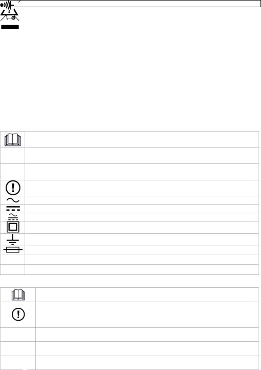
1 |
test pin |
2 |
Data Hold (DH) |
3 |
Range Hold (RH) |
4 |
range Select (S) |
5 |
Display |
6 |
Low Input impedance (LI) |
7 |
function switch |
8 |
release knob |
9 |
COM probe |
|
|
1 |
testsonde |
2 |
Hold-functie (DH) |
3 |
Range-functie (RH) |
4 |
bereikinstelling (S) |
5 |
lcd-scherm |
6 |
lage impedantie (LI) |
7 |
functieschakelaar |
8 |
wartel |
9 |
COM-sonde |
|
|
1 |
pointe de touche |
2 |
fonction Hold (DH) |
3 |
fonction Range (RH) |
4 |
sélection de plage (S) |
5 |
afficheur LCD |
6 |
faible impédance (LI) |
7 |
sélecteur de fonction |
8 |
manchon |
9 |
sonde COM |
|
|
1 |
punta de medición |
2 |
función Hold (DH) |
3 |
función Range (RH) |
4 |
selector de rango (S) |
5 |
pantalla LCD |
6 |
débil impedancia (LI) |
7 |
selector de función |
8 |
prensaestopas |
9 |
sonda COM |
|
|
1 |
Messspitze |
2 |
Hold-Funktion (DH) |
3 |
Range-Funktion (RH) |
4 |
Einstellknopf (S) |
5 |
LCD-Display |
6 |
niedrige Impedanz (LI) |
7 |
Funktionsschalter |
8 |
Kabelverschraubung |
9 |
COM-Sonde |
19.01.2011 |
2 |
©Velleman nv |
DVM 3218
User manual
1. Introduction
To all r esidents of th e European Union
Import ant environmental information about this product
This symbol on the device or the package indicates that disposal of the device after its lifecycle could harm the environment. Do not dispose o f the unit (or batteries) as unsorted municipal waste; it should be taken to a specialized company for recycling. This device shoul d be returned to your distrib utor or to a local recycling service. Respect the local environmental rules.
If in doubt, contact your local wa ste disposal authorities.
Thank you for choosin g Velleman! Please read the manual thorou ghly before bringing this dev ice into serv ice. If the device was dama ged in transit, don't install or use it and co ntact your deal er.
Refer to the Velleman ® Service and Quality Warranty on the last pages of t his manual.
For mo re info concerning this pro duct and the latest versi n of this user manual, ple ase visit our website ww w.velleman.eu.
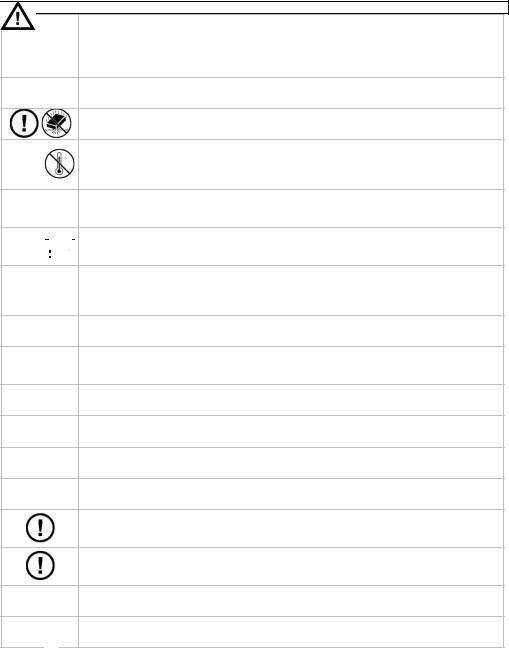
2. Used symbols
This symbol indicates: Read instructi ons
Not reading the instruction s and manual can lead to da mage, injury or death.
This symbol indicates: Danger
A hazardous condition or a ction that may result in injur y or death
This symbol indicates: Risk of danger/damage
Risk of a hazardous conditi on or action that may result in damage, injury or death
This symbol indicates: Attention; important inform ation
Ignoring this information c an lead to haza rdous situations.
AC (Alternating Current)
DC (Direct C urrent)
Both AC and DC
Double insula tion (class II-protection)
Earth
Fuse
Diode
Continuity
3. Safety Instructions
Read this manual thoro ughly. Familia rise yourself w ith the functio ns of the device before a ctually using it.
Only use the device for its intended p urpose. Using the device in an unauthoriz ed way will void the warra nty. Damage caused by disregard of certain guidelines in this manual is not covered by the warranty and the dealer will not acc ept responsibility for any e nsuing defect s or problems.
Follow the instructions below to guar antee a safe u se of the meter and all its functiona lities.
During u se of the meter, respect all directives conc erning protection against electroshocks and misuse. Never exc eed the indicated limits.
WARNI NG: To avoid electrical shock always disconnect the test leads prior to opening the housing.
19.01.20 11 |
3 |
©Vellema n nv |
DVM 3218
Remark : refer to the w arning on the back of the meter
Keep the device away from children a nd unauthorised users.
Protect t his device from shocks and abuse. Avoid br ute force when operating.
Avoid cold, heat and large temperature fluctuations. When the unit is moved from a cold to a warm location, leave it switc hed off until it has reached r oom temperat ure. This to a void condensation and measuring errors.
This is an installation category CA T III 600V / CAT II 1000V measuring instrument. Never use this equipm ent in a higher category than indicated. Re er to
§4 Overvoltage /installation cate gory.
Pollution degree 2-device. For indoor use only. Kee p this device away from rain, 


 moisture, splashing an d dripping liquids. Not for ind ustrial use. R efer to §5


 Pollutio n degree.
Before each use, make sure the test probes are in good condition. Always place your fingers behind the protective edges o f the test prob es while measuring! Never touch fre e terminals w hen the meter is connected to a circuit.
Make su re the meter is in the appropriate measurin g range befor e connecting it to a test circ uit.
Risk of electric shock during operation. Be very careful when measuring liv e circuits. Use extreme caution when m easuring volta ges higher tha n 60Vdc or 30 Vac rms.
Do not m easure circuits that may co ntain voltages > 1000V
Do not m easure curren t in circuits with voltages > 250V
Do not conduct resista nce, diode or c ontinuity measurements on live circuits.
Do not p erform low im pedance meas urements on voltages higher than 250V CAT II. Max. me asuring time is 3s.
When ca rrying out mea surements on a TV set or sw itching power circuits, alway s be aware that high amplit ude voltage pulses at the test points might damage the meter.
Do not r eplace interna l parts yourself. Replace da maged or lost a ccessories by identical ones with the same specific ations. Order spare accessories e.g. test probes at your d ealer.
Switch off the meter a nd remove test probes prior to replacing the battery or fu ses.
All modifications of the device are for bidden for safety reasons. Damage caused by user mo difications to t he device is no t covered by the warranty.
4. Overvoltage/installation categ ory
DMMs ar e categorized depending on the risk and s everity of tran sient overvolta ge that might occur at the point of te st. Transients are short-lived bursts of ene rgy induced in a system, e.g .
caused |
by lightning str ike on a power line. |
The existing categorie s according EN 61010-1 are: |
|
|
|
CAT I |
A CAT I-rated meter is suitable for measur ements on pr otected electronic circuits which |
|
are not directly connected t o mains power, e.g. electron ics circuits, co ntrol signals… |
|
A CAT II-rate d meter is suit able for measu rements in CA T I-environme nts and mono- |
CAT II |
phase appliances which are connected to the mains by m eans of a plu g and circuits in a |
normal domes tic environment, provided th at the circuit is at least 10m apart from a CAT |
|
|
IIIor 20m a art from a CAT IV-environment. E.g. household appliances, portable to ols… |
CAT III |
A CAT III-rate d meter is suitable for measurements in CAT I- and CAT II-environmen ts, |
|
as well as for measurement s on (fixed) m onoor poly-p hased appliances which are a t |
19.01.20 11 |
4 |
©Vellema n nv |

DVM 3218
least 10m apa rt from of a CAT IV-environ ment, and for measurements in or on distribution level equipment (fuse boxes, lighting circuits , electric ovens).
A CAT IV-rated meter is suitable for meas uring in CAT I-, CAT IIand CAT III- CAT IV environments as well as on the primary su pply level.
Note that for all measurements on equipm ent for which the supply cables run outdoo rs (either overhe ad or underground) a CAT I V meter must be used.
Warning:
This device was design ed in accorda nce with EN 61 010-1 installation category CAT III 600V / CAT II 1000V . This implies that certain restrictions in u se apply that are related to voltages and voltage peaks which c an occur within the environm ent of use. Refer to the tabl e above.
This device is suitable for measurements up to 1000V:
•Prot ected electronic circuits that are not directly connected to mains power, e.g. electronics
circu its, control signals, circuits b ehind isolatin g transformer…
• circu its that are dir ectly connecte d to mains power, but limite d to:
o |
measurements on mono-pha se appliances t hat are connected to the ma ins by means of a |
o |
p lug |
mono-phase ap pliances and c ircuits directly connected to the mains in a normal domestic |
|
|
e nvironment, p rovided that t he circuit is at least 10m apa rt from a CAT IIIor 20m ap art |
|
from a CAT IV-environment. E.g. household appliances, portable tools, light circuits at |
|
more than 10m from a distrib ution board … |
This device is suitable for measurements up to 600V:
•measurements in/ on low-voltage distribution b oards (distribution boards behind meter box)
•measurements on (fixed) monoor poly-phased appliances and circuits except in CAT IVenvi ronments (e.g . mains outlets , electric ovens, lighting circuits, bus bars, low-voltage distribution boards and circuit br eakers).
This device is NOT suitable for:
•Volt ages above 1000V
•Mea surements on distribution equipment and outdoor installations including meter boxes and equipment/circuits outside or re mote from the domestic envir onment e.g. circuits in sheds, garden houses and free-standing garages , or c ircuits using underground wiring e.g. garden lighting, pool-pum p...
This device i s only suitable for measurem ents up to 600V in CAT III and up to 10 00V in CAT II.
5. Pollution degree
IEC 61010-1 specifies different types of pollution environments, f or which differ ent protective measure s are necessary to ensure sa fety. Harsher environments require more protection, an d the protectio n against the pollution whic h is to be found in a certain environment depends mainly on the insulation and the enclosure pro erties. The pollution degree rating of the D VM indicates in which en vironment the device may b e used.
Pollution |
No pollution or only dry, nonconductive pollution occu rs. The pollution has no influ ence |
degree 1 |
(only to be found in herm etically sealed enclosures). |
Pollution |
Only nonco nductive pollution occurs. Occasionally, te mporary condu ctivity caused by |
degree 2 |
condensation is to be exp ected (home and office environments fall under this |
|
category). |
Pollution |
Conductive pollution occu rs, or dry nonconductive pollution occurs that becomes |
degree 3 conductive due to conden sation that is to be expecte d (industrial en vironments an d |
|
|
environments exposed to outside air - but not in contact with precip itation). |
Pollution |
The polluti on generates p ersistent cond uctivity caused by conductive dust or by r ain or |
degree 4 |
snow. (exposed outdoor environments and environm ents where high humidity levels |
|
or high con centrations of fine particles occur) |
Warning:
This device was design ed in accorda nce with EN 61 010-1 pollution degree 2. This implies th at certain restrictions in u se apply that are related to pollution whic h can occur within the
environ ment of use. Refer to the table above.
19.01.20 11 |
5 |
©Vellema n nv |

DVM 3218
This device is only suitable for measurements in Pollution degree class 2 environments.
6. Description
Refer to the illustratio n on page 2 of this manual.
Symbo l |
|
Description |
|
|
Low battery. |
|
|
|
Warning: To avoid false readings, whi ch could lead to possible elec tric shocks or |
||
|
personal injury, replace the battery as soon as the battery indicator appears. |
||
|
negative v alue |
|
|
|
Indicator f or alternating (current or voltage) |
||
|
Indicator f or direct (curre nt or voltage) |
||
|
The meter is in diode test mode. |
||
|
The meter is in continuity check mode. |
||
|
|
||
|
Manual ran ging mode enabled |
||
|
|
||
|
data hold function enable d |
||
|
|
|
|
µmVA |
Measurem ent units. |
||
MkΩ |
|||
0L |
Overrange indication |
||
|
|
|
|
Key |
Mode |
Description |
|
S |
All |
Select resistance, diode, continuity or capacity test. |
|
Select DC or AC current. |
|||
|
|
||
DH |
All |
Press to enter and exit the data hold m ode. |
|
|
|
Press to enter the manual ranging mo de and select the range |
|
RH |
V, Ω, A |
(press multiple times to browse throug h the availabl e ranges). |
|
|
|
Press and hold for 2 sec onds to return to auto-rangin g mode. |
|
LI |
V |
Press and hold to reduce meter imped ance from 10M Ω to 40KΩ. ( max. |
|
3s, <250V CAT II) |
|||
|
|
||
|
OFF |
switch off the meter |
|
switc h |
V |
voltage measurement |
|
Ω |
resistance / continuity / diode measur ment |
||
|
|||
|
A / A |
current measurment |
|
7. Op eration
Refer to the illustratio n on page 2 of this manual.
 Risk of elect ric shock during operation . Be very careful when meas uring live circ uits.
Before measu ring, always make sure the eter and/or t est probes are not damaged and verify the con nections, selected function a nd range.
Use measurin g probes that a re suitable for the selected measuring mo de.
•Neve r exceed the limit value for protection. This limit value is listed separately in the specifications for each range of m easurement.
•Only use the mete r in the indicated overvoltag e/installation category. Never measure voltages that might exceed the indicated category values.
•Disc onnect the test leads from th e tested circuit before selecting a different function.
•When carrying out measurements on a TV set or switching po wer circuits, a lways remem ber
that high amplitude voltage puls es at the test p oints might d amage the me ter.
•Always be careful when working with voltages above 60Vdc or 30Vac rms. Keep your fingers
behind the probe b arriers at all times during measurement.
• Do not measure cu rrent in circuits with voltages > 250V
•Neve r perform resistance, diode or continuity m easurements on live circuits . Make sure all capacitors in the circuit are discharged.
19.01.20 11 |
6 |
©Vellema n nv |

|
DVM 3218 |
General |
|
• |
Screw the desired test pin [1] fir mly on the m eter. |
• |
Switch the meter o n by moving the function sw itch [8] to the desired function. |
• |
Select the desired range within t he function by pressing the range select button [4]. |
“Hold” Function:
Press the “DH” but ton [2] to fre eze the value onto the display. The  symbol appears o n the display. Press again to resume n ormal operation.
“Range” function:
Press the “RH” button [3] to switch between automatic and manual range selection. When swit ching on the m eter it will be in auto-ranging mode. The m eter chooses the most suitable range for the selected function. When desired the range can be selected ma nually by pres sing
the “ RH” button; the  icon is s hown on the d isplay. Press multiple times to scroll throu gh the available range s. To return t o auto-ranging press and hold the “RH” button for 2 seconds.
“Select” button:
Press the “S” butto n [4] to select the desired range within the selected function.
Automat ic battery saving mode:
This function switches the meter to battery saving mode afte r ±8 min. Push any button o r move the function switch to reactivate the meter.
7.1 Voltage mea surements
Do not measure circuits where voltag es > 600V CA T III or > 10 00V CAT II may reside.
Always be careful when working with volta ges above 60 Vdc or 30Vac rms. Keep your fingers behind the probe ba rriers at all tim es during mea surement. Do not touch unused terminals whe n the meter is linked to a circuit which is b eing tested.
• Set t he function sw itch to V  a nd press the S button [4] t o choose betw een AC measurements AC or DC measurements.
•Con nect the COM p robe [9] and test pin [1] to the circuit under test.
• The measured valu e appears on the display.
•When desired, sele ct a range manually with the RH button [3 ].
•Press the LI butto n [6] to lower the imput impedance from 1 0MΩ to ±400 KΩ. This enables
the detection of in duced (ghost) voltages from nearby energized circuits. DO NOT use this feat ure in circuits where voltages higher than 2 50V (CAT II) may occur and do not press t he LI button longer th an 3s. In case of ghost-volt ages the meter reading will b e close to 0 V, whil e normal voltages will still read a considerable value (how ever incorrect as the low
impe dance of the meter is shunt ed with the impedance of the circuit under test).
Notes:
•F or DC-measurements: when a negative po larity is prese nt at the red t est pin [1], th e indicated value is preceded by a “-” sign.
• When the mea sured value is higher than the selected range limit, the display will sho w
“OL”. Select a higher range.
7.2Current meas urements
Do not measure current in circuits with voltages > 250V
Current measurements: max. 400mA.
Always be careful when working with volta ges above 60 Vdc or 30Vac rms. Keep your fingers behind the probe ba rriers at all tim es during mea surement.
• Set t he function sw itch to A  / A
/ A  .
.
•Select the AC or DC range with t he S button [4 ] (AC = alter nating current, DC = direct curr ent).
•Con nect the COM p robe [9] and test pin [1] in series with the circuit.
•Read the measure d value from t he display.
19.01.20 11 |
7 |
©Vellema n nv |
DVM 3218
• When desired, sele ct a range manually with the RH button [3 ].
Notes:
•F or DC-current measurements, when a negative polarity is present at th e red test pin [1],
|
the indicated value is preced ed by a “-” sig n. |
• |
When the mea sured value is higher than the selected range limit, the display will sho w |
|
“OL”. Select a higher range. |
7.3 Resistance m easureme nts
|
|
Do not perfo rm resistance |
measurements on live circuits. |
|
|
|
|
• |
Set t he function sw itch to Ω . |
|
|
• |
When necessary, p ush the S butt on [4] to select resistance measurement ( Ω). |
||
•Con nect the COM p robe [9] and test pin [1] to the circuit/component under test.
• |
The measured valu e appears on the display. |
|
• |
When desired, sele ct a range manually with the |
RH button [3 ]. |
Notes: |
|
|
o |
Never perform re sistance meas urements on a |
live circuit an d make sure a ll capacitors are |
o |
co mpletely discharged. |
|
For resistance measurements a bove 1MΩ the meter needs a few seconds to stabilize th e |
||
|
re ad-out. |
|
oShould the measured resistance exceed the selected range or in case of an open circuit, the display will show “OL”.
7.4 Continuity & diode test
Do not perform continuity or diode me asurements o n live circuits.
• Set t he function sw itch to Ω
 .
.
Continu ity test
• P ress the S but ton [4] until the  symbol appears on th e display.
•C onnect the CO M probe [9] and test pin [1 ] to the circuit under test.
•When the mea sured resistan ce is less than 35Ω a continuous beep is produced and the
resistance value is showed o n the display. Should the measured resista nce exceed the 4 00Ω or in cas e of an open circuit, the display will show “OL”.
Diode test |
|
|
• |
P ress the S but ton [4] until the |
symbol appears on t he display. |
• |
C onnect the test pin [1] to t he anode; con nect the COM probe [9] to t he cathode of t he |
|
|
d iode. The meter will display the approxima te forward voltage drop. If the lead connection |
|
|
is reversed, th e meter will di splay “OL”. |
|
Notes: |
|
|
• |
Never perform continuity or d iode measurements on a live circuit and m ake sure all |
|
|
c apacitors are completely discharged. |
|
• |
Measuring diodes that are part of a circuit might produce faulty results. Consider |
|
|
d isconnecting them from the circuit. |
|
8. Cle aning an d maintenance
Do not replace internal parts yourself. Replace damaged or lost access ories by identic al
o nes with the s ame specificat ions. Order spare accessories e.g. test probes at your dealer.
WARNING:
T o prevent fire, use proper fu ses
S witch off the meter and rem ove COM probe [9] and test pin [1] prior to replacing th e b attery or fuses.
WARNING: To avoid electrical shock always disconnect the COM prob e [9] and test pin [ 1] prior to opening the hous ing.
Remark: refer to the warnin g on the back of the meter
19.01.20 11 |
8 |
©Vellema n nv |

DVM3218
a. General mainenance:
•Wipe the device regularly with a moist, lint-free cloth. Do not use alcohol or solvents. b. Fuse Replacement
•Remove COM probe [9] and test pin [1] from the circuit under test.
•Switch off the multi-meter.
•Unscrew the test pin [1] and remove the front cover.
•Remove the fuse from the fuse holder and replace it with a new fuse of the same type and with the same specifications (F500mA/250V, Ø 5 x 20mm).
•Close the cover and re-install the test pin [1].
c. Battery Replacement
•Replace the battery as soon as the “  ” indication appears on the display.
•Remove COM probe [9] and test pin [1] from the circuit under test.
•Switch off the multi-meter.
•Unscrew the release knob [8] and remove the back cover.
•Replace the batteries by 2 new batteries of the same type and with the same specifications (1.5V – LR44).
•Close the battery compartment carefully and tighten the release knob [8].
Notes:
o Do not try to repair or calibrate the meter yourself; contact your dealer.
o Replace damaged accessories immediately; order them at your local dealer.
oDo not use the meter when it is damaged.
9.Technical specifications
This device is not calibrated when purchased!
Regulations concerning environment of use:
•Use this meter only for measurements in CAT I, CAT II and CAT III environments (see §4)
•Use this meter only in a pollution degree 2 environment (see §5)
Ideal temperature |
18-28°C |
Ideal relative humidity |
75% |
Max. altitude |
2000m |
Overvoltage/installation category |
CAT III 600V / CAT II 1000V |
Pollution degree |
Pollution degree 2 |
Operating temperature |
0°C~40°C (RH<80%) |
Storage temperature |
-10°C~60°C (RH<70, store without batteries!) |
fuses |
mA range F500mA / 250V, 5 x 20mm |
Overrange indication |
yes (‘OL’) |
Low battery indication |
yes ( ) |
Polarity indication |
‘-’ automatic indication |
“Hold” function |
yes |
Backlight function |
no |
Automatic switch off |
yes |
Power |
2 x 1.5V LR44 batteries V13GA (incl.) |
Dimensions |
230 x 35 x 20mm |
Weight |
±200g |
Accessoires |
manual / batteries |
19.01.2011 |
9 |
©Velleman nv |
DVM 3218
9.1 Voltage
F unction |
|
Range |
Resolution |
Accuracy |
|
|
340.0 mV |
0.1mV |
± 0.8% |
|
|
3.4 00 V |
1mV |
|
DCvoltage V |
|
34. 00 V |
10mV |
± 1.0% |
|
|
340. 00 V |
100mV |
|
|
|
600 V |
1V |
± 1.2% |
|
|
3.4 00 V |
1mV |
|
AC voltage ~V |
|
34. 00 V |
10mV |
± 1.2% |
|
340.0 V |
100mV |
|
|
|
|
|
||
|
|
600 V |
1V |
± 1.5% |
Max. inp ut voltage: 1000V |
|
|
|
|
Input im pedance: 10MΩ (<100pF) |
|
|
||
9.2 Current |
|
|
|
|
Function |
|
Range |
Resolution |
Accuracy |
DC |
|
34.0 0 mA |
0.01mA |
± 1.5% |
|
340.0 mA |
0.1mA |
||
|
|
|
||
AC ~ |
|
34.0 0 mA |
0.01mA |
± 1.8% |
|
340.0 mA |
0.1mA |
± 2.0% |
|
|
|
|||
Overloa d protection: F500mA/250V f use |
|
|
||
Max. Inp ut current: 40 0mA |
|
|
|
|
9.3 Resistance |
|
|
|
|
Function |
|
Range |
Resolution |
Accuracy |
|
|
|
340. 0 Ω |
0.1Ω |
± 0.8% |
|
|
|
3.400 |
kΩ |
1Ω |
|
Re sistance Ω |
|
34.00 kΩ |
10Ω |
± 1.2% |
|
|
340.0 |
kΩ |
100Ω |
|
|
|
|
|
|||
|
|
3.400 |
MΩ |
1kΩ |
± 2.0% |
|
|
34.00 |
MΩ |
10kΩ |
± 3.0% |
overload protection: 500V |
|
|
|
|
|
9.4 Diode/continuity |
|
|
|
|
|
Rang e |
Des cription |
Test Condition |
|
Built-in buzzer soun ds if resistance < ± 35Ω |
- |
|
Display reads approx. forward voltage of diode |
Open circ uit voltage: 3. 4V |
Use thi s device with original acce ssories only . Velleman nv cannot be held responsi ble in the event of dama ge or injury resulted from (incorrect) use of this device.
The inf ormation in this manual is subject to c hange withou t prior notic e.
© COPY RIGHT NOTICE
The copy right to this manual is owned by Velleman n v. All worldwide rights reserved. No part of this manual or may be copied, reproduced, translated or reduced to any electro nic medium or otherwise without the prior writ ten consent of th e copyright holder.
19.01.20 11 |
10 |
©Vellema n nv |
DVM 3218
GEBRUIKERSHANDLEI DING
1. Inleiding
Aan all e ingezetene n van de Euro pese Unie
Belangr ijke milieu-i nformatie be treffende dit product
Dit symbool op het toestel of de verpakking geeft aan d at, als het na zijn levenscyclus wordt weggeworpen, dit toestel schade kan toebrengen aan het milie u. Gooi dit toe stel (en eventuele batterijen) niet bij het gewone huishoude lijke afval; het moet bij een gespecialisee rd bedrijf terechtkomen voor recyclage. U moet dit toestel naar uw verdeler of naar een lokaal recyclagepunt brengen. Respecteer d e plaatselijke milieuwetgevi ng.
Hebt u vragen, cont acteer dan de plaatselijke autoriteiten inzake verwijdering.
Dank u voor uw aankoop! Lees deze handleiding gr ondig voor u het toestel in gebruik neemt. Werd het toestel besch adigd tijdens het transport, installeer het dan niet en ra adpleeg uw dealer.
Raadpleeg de Vellem an® serviceen kwaliteits garantie acht eraan deze ha ndleiding.
Voor meer informatie omtrent di t product en de meest recente versie van deze handleiding, zie www.velleman.e u.
2. Gebruikte sy mbolen
Dit symbool staat voor inst ructies lezen:
Het niet lezen van deze ins tructies en de handleiding k an leiden tot beschadiging, le tsel of de dood
Dit symbool betekent gevaar:
Gevaarlijke toestand of actie die kan leiden tot letsel of de dood
Dit symbool betekent risico op gevaar/schade:
Risico op het ontstaan van een gevaarlijk e toestand of actie die kan l eiden tot scha de, letsel of de d ood.
Dit symbool betekent aandacht, belangri jke informatie:
Het niet in acht nemen van deze informatie kan leiden tot een gevaar lijke toestand.
AC (wisselst room)
DC (gelijkstroom)
zowel wisselals gelijkstroom
Dubbele isol atie (klasse II-bescherming)
Aarding
Zekering
Diode
Continuiteit
3. Veiligheidsi nstructies
Lees de ze handleidin g grondig, leer eerst de funct ies van het to estel kennen voor u het gaa t gebruiken.
Gebrui k het toestel e nkel waarvoor het gemaakt is. Bij onoorde elkundig gebruik vervalt de garantie. D e garantie geldt niet voor sc hade door het negeren van bepaal de richtlijnen i n deze handleiding en uw dealer zal de verantwoordelijkh eid afwijzen voor defecten of problemen die hier rechtstreeks verband mee houden.
Volg de richtlijnen hie ronder om een veilig gebrui k te garanderen en alle functies van de meter ten volle te benutten.
Respecteer tijdens he t gebruik van de meter alle richtlijnen aangaande beveiliging tegen e lektroshocks en verkeerd ge bruik. De aan gegeven limietwaarden moge n nooit overschreden worden
19.01.20 11 |
11 |
©Vellema n nv |
DVM 3218
WAARSCHUWING:
Om elektrische schokken te vermijd en, verwijder de testsnoere n alvorens de behuizing te openen
Opmer king: dit is de vertaling van de waarschuw ing die op de achterkant va n het toestel bevindt.
Houd dit toestel uit de buurt van ki nderen en onbevoegden.
Bescherm het toestel tegen schokk en. Vermijd brute kracht tijd ens de bediening.
Vermij d koude, hitte en grote temperatuursschom melingen, Als het toestel van een ko ude naar een warme omgeving verplaatst wordt, laat het toestel dan ee rst voldoe nde op temperatuur komen. Dit om meetfouten en condensvorming te vermijd en.
Dit is een installatiec ategorie CAT III 600V / CA T II 1000V m eetinstrumen t. Gebrui k dit toestel no oit in een hogere CAT dan aangegeven. Zie §4
Overs panning-/installatiecateg orie.
Vervuilingsgraad 2-toestel, enkel g eschikt voor ge bruik binnenshuis! Stel dit 


 toestel niet bloot aan stof, regen, vochtigheid en opspattende vloeistoffen. Nie t


 geschik t voor industrieel gebruik. Zie §5 Vervuilingsgraad/Ve rvuilingsgra ad.
Controleer voor gebr uik indien de m eetsnoeren in goede staat verkeren. Houd tijdens metingen uw vingers a chter de beschermingsrand van de
meetpe nnen! Raak g een vrije meetbussen aan wa nneer de met er met een circ uit is verbonden.
Let erop dat de meter zich in de juiste stand bevi ndt alvorens d eze te verbind en met het testcircuit.
Elektrocutiegevaar tijdens het gebr uik van deze m ultimeter. Wees voorzichtig tijdens het meten va n een circuit o nder spanning. Wees uiterst voorzichtig bij metingen > 60 VDC o f 30 V RMS A C.
Meet n iet aan circuits waarin spanningen kunnen voorkomen > 1000 V.
Meet g een stroom in circuits met ee n spanning > 250 V.
Voer g een weerstand-, diodeof continuïteitsmetingen uit in cir cuits waarop spanni ng aanwezig is, of zou kunnen voorkomen.
Meet g een lage impe dantie in circuits met een sp anning hoger d an 250 V CAT II. Max. m eetduur: 3 se conden.
Wees voorzichtig bij metingen aan toestellen zoals tv's of schakelende voedin gen, Let op bij metingen op circuits zoal s TV’s of schakelende voedingen, er kunne n spanni ngspieken voo rkomen die de meter kunnen beschadigen
De gebruiker mag geen inwendige onderdelen ver vangen. Verva ng beschadig de of verloren accessoires enkel door accessoires van hetzelfde type of met dezelfd e specificaties. Bestel reserveaccessoires zoals meetsnoeren bij u w dealer.
Schakel de meter uit en verwijder d e testsnoeren vóór u de bat erij of zekering vervangt.
Om veiligheidsredenen mag u geen wijzigingen aa nbrengen. Sc hade door wijzigin gen die de gebruiker heeft a angebracht va lt niet onder d e garantie.
4. Overspannin g-/installatiecategorie
DMM’s w orden opgedeeld volgens het risico op en de ernst van s panningpieken die kunnen optrede n op het meetp unt. Spanning spieken zijn kortstondige uitbarstingen va n energie die geïnduc eerd worden in een systeem door bvb. blik seminslag op e en hoogspanningslijn.
19.01.20 11 |
12 |
©Vellema n nv |

DVM 3218
De best aande categorieën volgens E N 61010-1 zijn :
CAT I Een CAT I m eter is geschikt voor metinge n op bescherm de elektronis che circuits die niet rechtstreeks verbonden zij n met het lichtnet, bvb. Elekt ronische scha kelingen, stuursignalen …
CAT II Een CAT II m eter is geschi kt voor metingen in CAT I om gevingen en o p enkelfasige apparaten di e aan het lichtnet gekoppeld zijn door midd el van een ste kker en circui ts in een normale huiselijke omg eving, op voorwaarde dat h et circuit minst ens 10m verwijderd is van een CAT III omgeving, en minstens 20m van een C AT IV omgeving. Bvb. Huishou dapparaten, draagbare gereedschappen ...
CAT III Een CAT IIImeter is geschikt voor metingen in CAT I- en CAT II-omgevingen, alsook voor metinge n aan enkel- e n meerfasige (vaste) toestellen op meer dan 10 m van e en CAT IV-omge ving, en meti ngen inof aan distributiekas ten (zekeringk asten, verlichtingscircuits, elektrisch fornuis).
CAT IV Een CAT IV meter is geschikt voor meting en in CAT I, CAT II en CAT III omgevingen alsook metingen op het pri maire toevoer niveau.
Merk op dat voor metingen op kringen w aarvan de toevoerkabels buitenshuis lopen (zowel boven - als ondergronds) een CAT IV meter moe t gebruikt wor den.
Waarschuwing:
Dit toest el is ontworpen conform EN 61010-1 installatie categorie CAT III 600V / CAT II 1000V. Dit houd t bepaalde ge bruiksbeperkingen in die te maken hebben met voltages en spanningpi eken die kunn en voorkomen in de gebruiksomgeving, zi e tabel hierbov en.
Dit toes tel is geschi kt voor metingen tot max. 1000V aan:
•Beschermde circuit s die beveiligd of niet rechtstreeks verbon den zijn aan h et lichtnet zoals bv.
stuursignalen en m etingen aan elektronica, circ uits achter een scheidingstr ansformator
• Circu its rechtstree ks verbonden aan het lichtnet maar beperkt tot:
o |
Metingen aan |
monofaseappar aten verbond en met het lichtnet door mid del van een st ekker |
o |
(stopcontact) |
|
Metingen aan |
monofaseappar aten en circui ts rechtstreeks verbonden met het lichtnet in |
e en gewone hu iselijke omgev ing op meer dan 10m van e en CAT III om geving en 20m van e en CAT IV omgeving. (bvb. verlichtingskri ngen op meer dan 10m van de zekeringkas t)
Dit toes tel is geschi kt voor metingen tot max. 600V aan:
•Metingen in-/aan l aagspanningsb orden (zekerin gkast na de t ellerkast)
•Metingen aan monoen meerfas eapparaten en circuits uitgezonderd in een CAT IV-omge ving (bv. metingen aan stopcontacten, elektrisch for nuis, verlichti ngskringen, bu sbars, zekeringen
en automaten)
DIT TO ESTEL IS NIET GESCHIKT VOOR METINGEN VAN/AA N:
•Span ningen hoger dan 1000V
•Metingen aan distributieborden en buiteninstallaties. Hierond er vallen de tellerkast en toestellen/circuits buiten of los v an de huiselijke omgeving zo als kringen in schuurtjes, tuin huisjes en vrijstaande garage s- of kringen verbonden via ondergrondse leidingen zoals tuinv erlichting of vijverpompen.
Dit toestel is enkel geschikt voor metingen tot max . 600V in ee n CAT III omgeving en tot max. 10 00V in een C AT II omgevi ng
5. Vervuilingsg raad (pollution deg ree)
IEC 61010-1 specifieer t verschillend e types vervuilingsgraden we lke bepaalde risico’s met zich meebren gen. Iedere vervuilingsgraa d vereist specifieke bescherm ingsmaatregelen. Omgeving en met een hogere vervuilingsgraad he bben een beter e beschermin g nodig tegen mogelijke invloeden van de vers chillende types vervuiling die in deze omgeving kunnen voorkomen. Deze bescher ming bestaat h oofdzakelijk uit aagepaste is olatie en een aangepaste behuizing. De opgegeven Pollution d egree waarde geeft aan in w elke omgeving dit apparaat v eilig gebruikt kan worden.
Pollution |
Omgeving zonder, of m et enkel drog e- niet geleide nde vervuiling. De voorkomende |
degre e 1 |
vervuilin g heeft geen in vloed (Komt e nkel voor in uitzondelijke om gevingen). |
19.01.20 11 |
13 |
©Vellema n nv |
|
DVM 3218 |
|
Pollution |
Omgeving met enkel niet geleidende vervuiling, Uitzonderlijk kan condensatie |
|
degre e 2 |
voorkomen. (bv. huish oudelijkeen k antooromgeving) |
|
Pollution |
Omgeving waar geleide nde vervuiling voorkomt, of droge niet geleidende vervuiling |
|
degre e 3 |
die gelei dend kan worden door condensatie. (indust riële omgevin gen en omgevingen |
|
|
die blootgesteld worde n aan buitenlu cht zonder rechtstreeks contact met neerslag |
|
Pollution |
Omgeving waar freque nt geleidende vervuiling voor komt, bv. ver oorzaakt door |
|
degre e 4 |
geleiden d stof, regen of sneeuw (in openlucht en o mgevingen met een hoge |
|
|
vochtigh eidsgraad of h oge concentrat ies fijn stof). |
|
Waarschuwing:
Dit toest el is ontworpen conform EN 61010-1 verv uilingsgraad Po llution degree 2. Dit houdt bepaald e gebruiksbep erkingen in die te maken heb ben met de po llutie die kan voorkomen in de gebruiks omgeving, zie tabel hierbov en.
Dit toestel is enkel geschikt voor gebruik in omgevingen met Pollutio n degree 2 classificatie
6. Om schrijving
Raadpleeg de figuren op pagina 2 van deze handleiding.
Symbool |
Om schrijving |
|
Zwakke batterij. |
|
Waarschuw ing: Om onjuiste resultaten te vermijden, die tot elektroshocks en |
|
verwondin gen kunnen leiden, vervang de batterij van zodra dit symbool verschijnt. |
|
Negatieve waarde. |
|
Aanduiding voor wisselspanning of –stroom. |
|
Aanduiding voor gelijksp anning of –stro om. |
|
De meter b evindt zich in de diodetestmodus. |
|
De meter b evindt zich in de continuiteitstestmodus. |
|
|
|
Manuele b ereikinstelling actief. |
|
|
|
Data hold functie actief. |
|
|
µmVA |
Eenheden. |
MkΩ |
|
0L |
Buiten ber eik indicatie. |
Toets |
Modus |
Omschrijving |
|
S |
Alle |
Selectie weersta nd-, diode-, continuïteits en capaciteitsmeting. |
|
Selectie wissel- o f gelijkstroom. |
|||
|
|
||
DH |
Alle |
Druk om de data hold functie i n- of uit te schakelen |
|
|
|
Druk om manuele bereikinstelling te selecter en en bereik in te |
|
|
|
ste llen (achtereenvolgens indru kken om de verschillende |
|
RH |
V, Ω, A |
bereiken te doorlopen) |
|
|
|
Houd gedurende 2 seconden ingedrukt om na ar de |
|
|
|
automatische bereikinstelling t erug te keren. |
|
LI |
V |
Houd ingedrukt o m de impeda ntie van 10M Ω naar 40k Ω in te |
|
ste llen (max. 3 s, < 250 V CAT II). |
|||
|
|
||
|
OFF |
Druk om de multimeter uit te schakelen. |
|
|
V |
Spanningsmeting . |
|
schak elaar |
Ω |
Me ting weerstan d/continuïteit/ diode. |
|
|
A |
St roommeting. |
|
|
A |
||
|
|
19.01.20 11 |
14 |
©Vellema n nv |
DVM 3218
7. Gebruik
Raadpleeg de figuren op pagina 2 van deze handleiding.
E lektrocutiegevaar tijdens het gebruik van deze multimeter.
Wees voorzichtig tijdens het meten van een circuit onder spanning.
C ontroleer vooraleer te meten altijd indien de aansluiting en, de functie en het bereik c orrect zijn ingesteld en indie n het toestel e n/of de testsnoeren niet bes chadigd zijn. Gebruik testsn oeren die geschikt zijn voor de gekozen me etmodus.
•Over schrijd nooit d e grenswaard en! Deze waarden worden ve rmeld in de sp ecificaties van elk meetbereik.
•Gebr uik de meter enkel voor het meten in de aangeduide meetcategorie-in stallaties en meet geen voltages die de aangeduide waarden kun nen overschrijd en.
•Kop el de testsnoe ren los van he t meetcircuit vooraleer u ee n andere functie kiest.
•Let o p bij metinge n op circuits zo als tv’s of schakelende voedingen, er kunn en span ningspieken voorkomen die de meter kunn en beschadige n.
•Wees uiterst voorzichtig wanneer u werkt met voltages boven 60VDC of 30 VAC RMS. Houd tijdens metingen uw vingers te allen tijde achte r de bescherm ingsrand van de meetpennen!
•Meet geen stroom in circuits met een spanning > 250V
•Voer nooit weerstandsmetingen, continuïteitstest of diodetest uit op schakelingen die onder span ning staan. Ve rgewis uzelf ervan dat cond ensatoren die zich in het circuit bevinden ontla den zijn.
Algemeen
•Schroef de gewenste testsonde [1] stevig op de meter.
• |
Scha kel de meter in door de func tieschakelaar [8] op de gew enste functie te plaatsen. |
• |
Kies het gewenste bereik met de instelknop [4]. |
“Hold” functie:
Druk op de “DH” t oets [2]om de weergegeven waarde op het scherm te bevriezen. Het  sym bool verschijnt op het scher . Om het sch erm terug vrij te geven druk opnieuw op d e knop
“Range” functie:
Druk op de “RH” t oets [3] om o ver te schakele n van automatische naar m anuele bereiksinstelling.
Bij het inschakelen staat de mete r in automatis che modus, Het toestel kiest zelf het meest geschikte bereik v oor de gekozen functie. Indie n gewenst ka n het bereik toch manueel
geko zen worden d oor op de “RH ” toets te drukken; het  icoon is weerge geven op het scherm.Iedere druk op de toets s telt een ander bereik in. Om terug te keren naar Automatische inste lling, houd de “RH” toets 2 seconden inge drukt.
“Select” functie:
Druk op de “S” toets [4] om het gewenste ber eik te kiezen.
Automa tische batter ijspaarstand:
Het toestel gaat au tomatisch in b atterijspaarst and na ±8min. Druk om het even welke functietoets in of verplaats de fu nctieschakelaar om het toestel uit de slaapstand te halen.
7.1 Spanningsme tingen
Meet niet aan circuits waarin spanningen kunnen vo orkomen > 600V CAT III of 1 000V CAT II
Wees uiterst v orzichtig wan neer u werkt m et voltages b oven 60Vdc of 30Vac rms. H ou tijdens metinge n uw vingers te allen tijde achter de besch ermingsrand van de meetpennen! R aak geen aan sluitbussen aa n tijdens de meting
•Plaa ts de functieschakelaar op V  en druk op de S toets [4 ] om te kieze n tussen wisselspanningsme ting AC of gelijkspanningsmeting DC.
• Verbind de COM-so nde [9] en de testsonde [1] met het te m eten circuit.
•De gemeten spanning kan afgelezen worden op de display.
•Selecteer manueel bereik met de “RH” toets [3 ] indien gewenst.
19.01.20 11 |
15 |
©Vellema n nv |
 Loading...