


Total solder points: 85
Difficulty level: beginner 1 2 3 4 5 advanced
SIGNAL TRACER / INJECTOR KIT
K7000
|
|
|
|
|
|
|
|
|
|
g. |
|
|
|
|
|
|
|
|
|
tin |
|
|
|
|
|
|
|
|
|
oo |
|
|
|
|
|
|
|
|
|
sh |
|
|
|
|
|
|
|
|
|
ble |
|
|
|
|
|
|
|
|
|
ou |
|
|
|
|
|
|
|
|
|
dio tr |
|
|
|
|
|
|
|
|
|
s |
au |
|
|
|
|
|
|
|
|
fie |
|
|
|
|
|
|
|
|
|
pli |
|
|
|
|
|
|
|
|
|
m |
|
|
|
|
|
|
|
|
|
|
Si |
|
|
|
|
|
|
|
|
|
|
ILLUSTRATED ASSEMBLY MANUAL |
H7000IP-1 |

VELLEMAN NV
Legen Heirweg 33
9890 Gavere
Belgium Europe www.velleman.be www.velleman-kit.com

Features & Specifications
Features
This signal tracer /injector has been designed to inject or detect a specific signal into an audio circuit in need of repair (such as amplifiers, radios, tone controls, ...) so as to detect the fault. In this way problems can be traced more easily. The signal tracer may also be used as a simple monitor or amplifier.
Specifications :
Output power: 0.5W / 8ohm
Power supply: 7-9VAC or 9-12VDC / 150mA Dimensions: 60 x 53mm (2.4" x 2.1")
Injector:
0-2.5Vrms output (adjustable) Output impedance: 1.5Kohm Frequency: ± 1kHz
Tracer:
3.5mV to 10Vrms sensitivity (adjustable) Gain: 40dB
Input impedance: 50Kohm
3
Assembly hints
1. Assembly (Skipping this can lead to troubles ! )
Ok, so we have your attention. These hints will help you to make this project successful. Read them carefully.
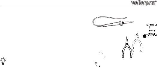
1.1 Make sure you have the right tools:
A good quality soldering iron (25-40W) with a small tip.
Wipe it often on a wet sponge or cloth, to keep it clean; then apply solder to the tip, to give it a wet look. This is called ‘thinning’ and will 
 protect the tip, and enables you to make good connections. When solder rolls off the tip, it needs cleaning.

Thin raisin-core solder. Do not use any flux or grease.
A diagonal cutter to trim excess wires. To avoid injury when cutting excess leads, hold the lead so they cannot fly towards the eyes.
Needle nose pliers, for bending leads, or to hold components in place.
Small blade and Phillips screwdrivers. A basic range is fine. 0. 00 0 For some projects, a basic multi-meter is required, or might be handy 
1.2 Assembly Hints :
Make sure the skill level matches your experience, to avoid disappointments.
Follow the instructions carefully. Read and understand the entire step before you perform each operation.Perform the assembly in the correct order as stated in this manual
Position all parts on the PCB (Printed Circuit Board) as shown on the drawings.Values on the circuit diagram are subject to changes.
Values in this assembly guide are correct*Use the check-boxes to mark your progress.
Please read the included information on safety and customer service
* Typographical inaccuracies excluded. Always look for possible last minute manual updates, indicated as ‘NOTE’ on a separate leaflet.
4
 Loading...