

USB PIC PROGRAMMER
&
TUTOR BOARD
USB PIC PROGRAMMER
&
TUTOR BOARD
FR PROGRAM MATEUR DE PIC SUR PORT USB ET TUTORIEL
NL USB PIC PROGRAMMER EN LEERMODULE
DE USB PIC-PROGRAMMER U ND EXPERIMENTIERKASTEN
ES PROGRAMADOR PIC USB Y PLACA BOARD DE
WWW.VELLEMANPROJECTS.EU
EXPERIMENTACIÓN
(*) The Micro chip name and logo , PIC, and PICmicro ar e registered tra demarks of Micro chip Technology Inc . in the USA and other countries
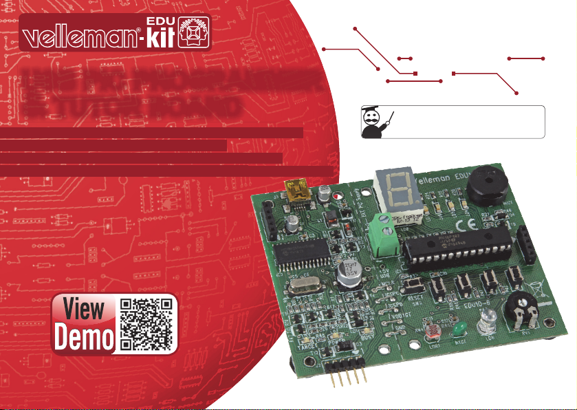
EDU10
DISCOVER THE
WORLD OF ELECTRONICS
UK See the product page on our website for the latest available translated manual.
NL Download de laatst beschikbare vertaalde handleiding op de product-pagina van onze website.
FR Consultez la fi che technique sur notre site web pour la toute dernière version de la traduction du mode d'emploi.
D Eine aktuelle Version der deutschen Bedienungsanleitung fi nden Sie auf der Produktseite unserer Website
ES Para descargarse el manual del usuario en español más recientes, consulte la página del producto en nuestra web.
WARRANTY :
This product is guaranteed against defects in components and construction from the moment it is purchased and for a period of TWO YEAR starting from the date of sale. This guarantee is only valid if the unit is submitted together with the original purchase invoice. VELLEMAN Ltd limits its responsibility to the reparation of defects or, as VELLEMAN components Ltd deems necessary, to the replacement or reparation of defective components. Costs and risks connected to the transport, removal or placement of the product, or any other costs
directly or indirectly connected to the repair, will not be reimbursed by VELLEMAN components Ltd. VELLEMAN components Ltd will not be held responsible for any damages caused by the malfunctioning of a unit.
GARANTIE:
Ce produit est garanti contre les défauts des composantes et de fabrication au moment de l’achat, et ce pour une période de deux ans à partir de la date d’achat. Cette garantie est uniquement valable si le produit est accompagné de la preuve d’achat originale. Les obligations
de VELLEMAN S.A. se limitent à la réparation des défauts ou, sur seule décision de VELLEMAN S.A., au remplacement ou à la réparation des pièces défectueuses. Les frais et les risques de transport, l’enlèvement et le renvoi du produit, ainsi que tous autres frais liés directement ou indirectement à la réparation, ne sont pas pris en charge par VELLEMAN S.A. VELLEMAN S.A. n’est pas responsable des dégâts, quels qu’ils soient, provoqués par le mauvais fonctionnement d’un produit.
WAARBORG:
Dit produkt is gewaarborgd wat betreft gebreken in materialen en vakmanschap op het ogenblik van de aankoop en dit gedurende een periode van TWEE JAAR vanaf de aankoop. De waarborg geldt enkel indien het produkt voorgelegd wordt samen met het origineel aankoop
bewijs. De verplichtingen van VELLEMAN N.V. beperken zich tot het herstellen van defecten of, naar vrije keuze van VELLEMAN N.V., tot het vervangen of herstellen van defecte onderdelen. Kosten en risico’s van transport; het wegnemen en terugplaatsen van het produkt,
evenals om het even welke andere kosten die rechtstreeks of onrechtstreeks verband houden met de herstelling, worden niet door VELLEMAN N.V. vergoed. VELLEMAN N.V. is niet verantwoordelijk voor schade van gelijk welke aard, veroorzaakt door het falen van een
product.
GARANTIE:
Dieses Produkt trägt eine Garantie für fehlerhaftes Material oder Verarbeitungsschäden im Moment des Ankaufs. Sie ist ZWEI JAHRE gültig ab Ankaufsdatum. Die Garantie kann nur beansprucht werden, wenn das Produtk mit der Originalrechnung abgegeben wird. Die
Verpfl ichtungen der VELLEMAN AG beschränken sich auf die Aufhebung der Fehler, oder, nach freier Wahl der VELLEMAN AG, auf den Austausch oder die Reparation der fehlerhaften Teile. Kosten und Risiken des Transports; das Entfernen und Wiedereinsetzen des
Produkts, sowie alle anderen Kosten die direkt oder indirekt mit der Reparation in Verbindung gebracht werden können, werden durch die VELLEMAN AG nicht zurückerstattet. VELLEMAN AG ist nicht für Schäden gleich welcher Art, entstanden aus der fehlerhaften Funktion
des Produkt, haftbar.
GARANTÍA:
El producto está garantizado durante un período limitado de DOS AÑO a partir de la fecha original de compra. La garantía sólo tendrá validez cuando se presente el producto con la factura de compra original. VELLEMAN S.A. se limitará a reparar defectos pero es libre de
reparar o reemplazar partes defectuosas. VELLEMAN S.A. no reembolsará los gastos de transporte o riesgos, ni los gastos para trasladar y reinstalar el producto así como todo otro gasto directamente o indirectamente relacionado con la reparación. VELLEMAN S.A. no
asumirá ninguna responsabilidad por daños de cualquier naturaleza causados por un producto defectuoso.
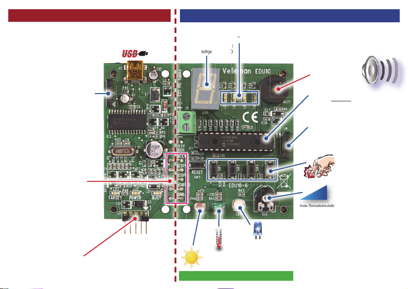
Tutor board section • Sectie leermodule • Section du tutoriel • Experimentierkasten • placa board de experimentación
Programmer
*
-st
t
elli
elli
e
elli
ell
elli
lli
llli
lli
ge L
ge
ge gegegege
ge
g
e
gggeg ggggg
g
t
es
On-board IN & OUTPUT
A
t
a
C
C
F
®
(*) PICKit 2
compatible • programmer compatibel met een PICKit2-programmer •
programmateur compatible avec un programmateur PICKit2 • kompatibel mit PICKit2Programmer • compatible con el programador PICKit2
Programmer
*
Tutor board section • Sectie leermodule • Section du tutoriel • Experimentierkasten • placa board de experimentación
indicator LEDs for power supply and programming mode • indicatieleds voor voedingsspanning en
programmeermode • indicateurs LED pour l’alimentation et le mode de programmation • Anzeige-LEDs für Stromversorgung
und Programmiermodus • indicadores LED para la alimentación y el modo de programación
LED-Digit • Led-digit • Digit
à LED • 1-stellige LED • LED
de 1 dígito
i
Buzzer • zoemer • ronfl eur •
Summer • zumbador
On-board PICKIT 2® fi rmware port (ICSP)
•
Ingebouwde PICkit 2® fi rmware-poort (ICSP) •
Port micrologiciel PICKIT 2® intégré (ICSP) • Eingebauter PICKIT 2®-Firmwareport (ICSP) • Puerto
fi rmware PICKIT 2® incorporado (ICSP
On-board program lines connection •
Ingebouwde verbinding van programmalijnen • Connexion des lignes de programme intégrée •
Eingebauter Anschluss für Programmlinien
• Conexión incorporada para líneas de programa
External ICSP programming •
ICSP externe • External ICSP programming • programación ICSP externa
Externe ICSP-programmering • Programmation
Included, geleverd met, livré avec, Lieferung
mit, incluye PIC16F882
On-board programmer port (ICSP)
• Ingebouwde programmeerpoort (ICSP) • Port
de programmation intégré (ICSP) • Eingebauter
Programmierport (ICSP) • Puerto de programación
incorporado (ICSP)
4x digital inputs • 4x digitale ingangen • 4x entrées numériques • 4x
digitaler Eingang • 4x entrada digital
Analog signal simulation with
n
potentiometer •
o
analogique avec potentiomètre • Ana-
an
loge Signalsimulation mit Potentiometer • Simulación de
la señal analógica con potenciómetro
°C °F
Temperature resistor (NTC) • temperatuursgevoelige weerstand •
hängigen Widerstande • resistencia según de la temperatura
Light dependant resistor (LDR) • lichtgevoelige weerstand • Résistance photo-dépendante • resistencia
según de la intensidad luminosa
On-board IN & OUTPUT
White LED for PWM dimming •
blanche pour variation MLI • eine weiße LED über PWM-Signal dimmen •
ajustar la intensidad luminosa de un LED blanco con una señal PWM
Witte led voor PWM-dimming • LED
Simulation de signal
thermistance • temperaturab-

p. 4
Feautures
Specifi cations
Feautures
• PICKit2 compatible programmer
• includes: PIC16F882
• tutor sample programs in "C" and "Assembler" can be downloaded:
• button input reading
• LED on/off
• LED blinking
• buzzer and display driving
• LED brightness
• analog value reading
• ...
• read up to 4 push buttons for digital in simulation
• light up to 4 LEDs for digital out simulation
• read the value of a potentiometer (analog value)
• read the value of a temperature dependent resistor (NTC)
• read the value of a light dependent resistor (LDR)
• dim a white LED using PWM signal
• learn how to drive a LED digit
• learn how to drive a buzzer
Specifi cations
• experiment module can be powered via USB
• power output to target is supported
• indicator LEDs for power supply and programming mode
• dimensions:
• programming and learning module: 90 x 74 mm / 3.54 x 2.91"
• programmer only: 34 x 74 mm / 1.34 x 2.91"
USB PIC PROGRAMMER AND TUTOR BOARD
- UK -
USB PIC PROGRAMMER AND TUTOR BOARD
Download and extract PICkit 2 V2.61
Download software package with demos
Download software package with demos
• Follow this link to Velleman support: http://www.velleman.eu/support/
• Click on “Downloads per product (drivers, manuals, software, ...)”.
• Enter Product code: EDU10 and then click Search button.
• Download and extract the demos for EDU10.
Download and extract PICkit 2 V2.61
• In the folder “PICkit 2 v2.61 run setup.exe”. This will install the program PICkit 2 v2.61 with the .NET framework.
• When installation is complete, you can connect the EDU10 to the computer’s USB port.
• Double click the “PICkit 2 v2.61” icon on the desktop.
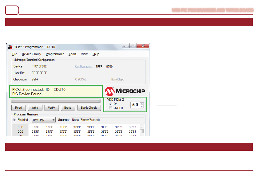
• The “PICkit 2 Programmer - EDU10” should show text:
“PICkit 2 connected ID = EDU10
PIC Device Found”
- UK -
p. 5
p. 6
Run the EDU10 Startup Demo
Running other demos
Run the EDU10 Startup Demo
• Click on “On” check box in the panel “VDD PICkit 2” to turn the EDU10 power on.
• Use the “Up” arrow to adjust the voltage to 5V.
• Now the PIC16F882 on EDU10 should be running its default “Startup” program.
Running other demos
In the software package for the EDU10 there are several demos written in assembly and C.
You can use the PICkit 2 Programmer software to reprogram the PIC16F882 on the EDU10 board with the downloaded demo code.
USB PIC PROGRAMMER AND TUTOR BOARD
You can test the board by pressing buttons SW1..SW4
and RESET (SW5). There should be following response:
SW1:
- Turn on LD7
- Show ‘7’ on the 7-segment display.
SW2:
- Turn on LD6
- Show ‘6’ on the 7-segment display.
SW3:
- Turn on LD5
- Show ‘5’ on the 7-segment display.
SW4:
- Turn on LD4
- Sound is generated.
- Display all segments+dot on the 7-segment display.
RESET mode:
- LDR is programmed as light detector.
- LDR turns LED LD8 on/off depending on light.
- Potentiometer RV1 changes the display brightness.
- If NTC voltage <1V or >4V then “E” (Error) is displayed on the
7-segment display.
- UK -
USB PIC PROGRAMMER AND TUTOR BOARD
Here are the steps to make the board to work as “Proximity_Detector”.
Edit and compile the source code of the demos
Here are the steps to make the board to work as “Proximity_Detector”.
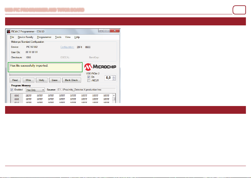
• In the PICkit 2 Programmer’s menu select File -> Import Hex.
• Then locate the “C” folder in the downloaded software package.
• There locate the fi le Proximity_Detector.X.production.hex in the subfolder \
Proximity_Detector.X\dist\default\production and click Open button.
• Then click the Write button to program the device. The white LED should
now start fl ashing.
• If you now put a refl ecting object near the LED then a buzzer ‘beep’ is
generated.
• The beep pitch is proportional to the refl ection (distance of object).
Edit and compile the source code of the demos
• To edit and compile the ASM code examples you have to download and install MPLAB® X or MPLAB® IDE.
• To edit the and compile the C code examples you have to download and install MPLAB® X and XC8 compiler.
• You’ll fi nd them at http://www.microchip.com. Click on Design Support / Development Tools.
• MPLAB X requires Java to be installed in order to run.
• You can use this link to download Java for your computer: http://www.java.com/en/download/index.jsp
Important: When compiling the ASM demo projects in MPLAB® X, please use the menu option or button “Clean and Build Project” when fi rs
compiling the code. If not done, you’ll get an error message.
The ASM demos written in MPLAB® X are in the subfolder ASM_X and the demos written in MPLAB® IDE are in the subfolder ASM_MPLAB.
p. 7
t time
- UK -

p. 8
Kenmerken
Specifi caties
Kenmerken
• programmer compatibel met een PICKit2-programmer
• geleverd met: PIC16F882
• u kunt voorbeeldprogramma’s in “C” en “Assembler” downloaden:
• uitlezen bediening drukknop
• LED aan/uit
• LED knippert
• aansturen buzzer en display
• LED helderheid
• uitlezen analoge waarden
• ...
• tot 4 drukknoppen uitlezen voor de simulatie van digitale ingang
• tot 4 leds oplichten voor de simulatie van digitale uitgang
• de waarde uitlezen van een potentiometer (analoge waarde)
• de waarde uitlezen van een temperatuursgevoelige weerstand (NTC)
• de waarde uitlezen van een lichtgevoelige weerstand (LDR)
• een witte led dimmen met een PWM-signaal
• leer een led-digit aansturen
• leer een buzzer aansturen
Specifi caties
• experimenteergedeelte kan via USB gevoed worden
• ondersteuning van voedingsuitgang naar doel
• indicatieleds voor voedingsspanning en programmeermode
• afmetingen:
• programmeer- en leermodule: 90 x 74 mm
• programmer: 34 x 74 mm
USB PIC PROGRAMMER EN LEERMODULE
- NL -

USB PIC PROGRAMMER EN LEERMODULE
Installeer PICkit 2 V2.61
Download het softwarepakket met demo’s
Download het softwarepakket met demo’s
• Volg de link http://www.Velleman.eu/support/ voor Velleman-ondersteuning
• Klik op “Downloads per product (drivers, manuals, software, …)”.
• Geef de productcode EDU10 in en klik daarna op Search.
• Download en pak de demo’s uit voor EDU10.
Installeer PICkit 2 V2.61
• Voer setup.exe uit in de map “PICkit 2 v2.6”. Hiermee wordt het programma PICkit 2 v2.61 geïnstalleerd met het .NET framework
• Wanneer de installatie voltooid is, kunt u de EDU10 aansluiten op de USB-poort van de computer.
• Dubbelklik op het “PICkit 2 v2.61”-icoon op het bureaublad.
• De “PICkit2-programmer – EDU10” zou de volgende tekst moeten weergeven:
“PICkit 2 connected ID = EDU10
PIC Device Found”
.
- NL -
p. 9

p. 10
De EDU10 opstartdemo uitvoeren
Andere demo’s uitvoeren
De EDU10 opstartdemo uitvoeren
• Vink “ON” aan in het vak “VDD PICkit 2” om de EDU10 in te schakelen.
• Gebruik de omhoog-pijltjestoets om de spanning te regelen op 5V.
• De PIC16F882 zou nu op EDU10 het standaard opstartprogramma moeten uitvoeren.
U kunt de module testen door de knoppen SW1…SW4 en
RESET (SW5) in te drukken. U zou het volgende antwoord
moeten krijgen:
SW1:
SW2:
SW3:
SW4:
RESET mode:
Andere demo’s uitvoeren
In het softwarepakket voor de EDU10, zijn verschillende demo’s geschreven in assembly en C.
U kunt de PICkit 2-programmer gebruiken om de PIC16F882 te herprogrammeren op de EDU10-module met de gedownloade democode.
USB PIC PROGRAMMER EN LEERMODULE
- Turn on LD7
- Show ‘7’ on the 7-segment display.
- Turn on LD6
- Show ‘6’ on the 7-segment display.
- Turn on LD5
- Show ‘5’ on the 7-segment display.
- Turn on LD4
- Sound is generated.
- Display all segments+dot on the 7-segment display.
- LDR is programmed as light detector.
- LDR turns LED LD8 on/off depending on light.
- Potentiometer RV1 changes the display brightness.
- If NTC voltage <1V or >4V then “E” (Error) is displayed on the
7-segment display.
- NL -

USB PIC PROGRAMMER EN LEERMODULE
Volg de onderstaande stappen om de module te laten functioneren als “Proximity_Detector”
De broncode van de demo’s wijzigen en compileren
Volg de onderstaande stappen om de module te laten functioneren als “Proximity_Detector”
• In het menu van de PICkit 2-programmer, selecteer File -> Import Hex.
• Lokaliseer vervolgens de “C”-folder in het gedownloade softwarepakket.
• Zoek het bestand “Proximity_Detector.X.production.hex” in de subfolder “\
Proximity_Detector.X\dist\default\production” en klik op Open.
• Klik daarna op Write om het toestel te programmeren. De witte led zou nu
moeten beginnen te knipperen.
• Indien u nu een refl ecterend voorwerp plaatst naast de led, dan hoort u een
pieptoon.
• De toonhoogte van de pieptoon geeft de afstand tot het object aan.
De broncode van de demo’s wijzigen en compileren
• Om de ASM-codevoorbeelden te wijzigen en te compileren, moet u MPLAB® X of MPLAB® IDE downloaden en installeren.
• Om de C-codevoorbeelden te wijzigen en te compileren, moet u MPLAB® X en XC8 compiler downloaden en installeren.
• U kunt deze vinden via http://www.microchip.com. Klik op “Design Support / Development Tools”..
• MPLAB X vereist Java om te kunnen werken.
• Gebruik de link http://www.java.com/en/download/index.jsp om Java te downloaden op uw computer
Belangrijk: Bij het compileren van de ASM-demoprojecten in MPLAB® X, klik op “Clean and Build Project” indien de code voor de eerste keer gecom-
pileerd wordt. Zoniet krijgt u een foutmelding.
De ASM-demo’s geschreven in MPLAB ® X bevinden zich in de subfolder ASM_X en de demo’s geschreven in MPLAB® IDE bevinden zich in
de subfolder ASM_MPLAB.
p. 11
- NL -

p. 12
Caractéristiques
Spécifi cations
Caractéristiques
• programmateur compatible avec un programmateur PICKit2
• livré avec: PIC16F882
• les programmes d’exemple en “C” et “Assembler” peuvent être téléchargés:
• lire un appui bouton-poussoir
• LED allumée/éteinte
• LED clignotante
• piloter un buzzer et affi cheur
• luminosité LED
• lire la valeur analogique
• ...
• lire jusqu’à 4 boutons-poussoirs pour la simulation d’entrée numérique
• illuminer jusqu’à 4 LEDs pour la simulation de sortie numérique
• lire la valeur d’un potentiomètre (valeur analogique)
• lire la valeur d’une thermistance (CTN)
• lire la valeur d’une résistance photo-dépendante (LDR)
• faire varier la luminosité d’une LED blanche avec un signal PWM
• piloter un chiffre LED
• piloter un buzzer
Spécifi cations
• il est possible d’alimenter le tableau d’expérimentation par USB
• support de sortie d’alimentation vers cible
• indicateurs LED pour l’alimentation et le mode de programmation
• dimensions:
• programmation et module d’apprentissage: 90 x 74 mm
• programmateur seulement : 34 x 74 mm
- FR -
PROGRAMMATEUR DE PIC SUR PORT USB ET TUTORIEL

PROGRAMMATEUR DE PIC SUR PORT USB ET TUTORIEL
Installez PICkit 2 V2.61
Téléchargez le progiciel avec démos
Téléchargez le progiciel avec démos
• Suivez le lien http://www.velleman.eu/support/ pour accéder au support Velleman
• Cliquez sur “Downloads per product (drivers, manuals, software,…)”.
• Saisissez la référence EDU10 et puis cliquez sur Search.
• Téléchargez et extrayez les démos pour l’EDU10.
Installez PICkit 2 V2.61
• Exécutez setup.exe à partir du dossier “PICkit 2 v2.61” Le programme PICkit 2 v2.61 s’installera avec le .NET Framework
• Une fois l’installation terminée, il est possible de connecter l’EDU10 au port USB de l’ordinateur.
• Double-cliquez sur l’icône “PICkit 2v2.61” sur le bureau.
• Le “programmateur PICkit 2 – EDU10” devrait affi cher le texte suivant :
“PICkit 2 connected ID = EDU10
PIC Device Found”
- FR -
p. 13

p. 14
Exécuter la démo de démarrage de l’EDU10
Exécuter d’autres démos
Exécuter la démo de démarrage de l’EDU10
• Cochez la case “ON” dans le panneau “VDD PICkit 2” pour activer l’EDU10.
• Utilisez la touche fl échée haut pour régler la tension sur 5V.
• Maintenant, le PIC16F882 devrait exécuter son programme de démarrage par défaut sur l’EDU10.
Exécuter d’autres démos
Dans le progiciel pour l’EDU10, plusieurs démos sont écrites en assembleur et en C.
Il est possible d’utiliser le programmateur PICkit 2 pour reprogrammer le PIC16F882 sur le module EDU10 avec le code démo téléchargé.
PROGRAMMATEUR DE PIC SUR PORT USB ET TUTORIEL
Vous pouvez tester le module en appuyant sur les boutons
SW1…SW4 et RESET (SW5). La réponse suivante devrait
s’affi cher :
SW1:
- Turn on LD7
- Show ‘7’ on the 7-segment display.
SW2:
- Turn on LD6
- Show ‘6’ on the 7-segment display.
SW3:
- Turn on LD5
- Show ‘5’ on the 7-segment display.
SW4:
- Turn on LD4
- Sound is generated.
- Display all segments+dot on the 7-segment display.
RESET mode:
- LDR is programmed as light detector.
- LDR turns LED LD8 on/off depending on light.
- Potentiometer RV1 changes the display brightness.
- If NTC voltage <1V or >4V then “E” (Error) is displayed on the
7-segment display.
- FR -

PROGRAMMATEUR DE PIC SUR PORT USB ET TUTORIEL
Suivez les étapes suivantes pour faire fonctionner le module comme “Proximity_Detector”
Editer et compiler le code source des démos
Suivez les étapes suivantes pour faire fonctionner le module comme “Proximity_Detector”
• Dans le menu du programmateur PICkit 2, sélectionnez “File -> Import Hex”.
• Puis, localisez le répertoire “C” dans le progiciel téléchargé.
• Retrouvez le fi chier “Proximity_detector.X.production.hex” dans le sous-
répertoire \Proximity_Detector.X\dist\default\production et cliquez sur le
bouton Open.
• Ensuite, cliquez sur le bouton Write pour programmer l’appareil. La LED
blanche devrait commencer à clignoter.
• Lorsque vous placez maintenant un objet refl étant à côté de la LED, un bip
sonore s’émettra.
• Le niveau sonore du bip est proportionnel à la réfl exion (distance de l’objet).
Editer et compiler le code source des démos
• Pour éditer et compiler les exemples de codes ASM, téléchargez et installez MPLAB® X ou MPLAB® IDE.
• Pour éditer et compiler les exemples de codes C, téléchargez et installez MPLAB® X et XC8 compiler.
• Vous les trouverez sur http://www.microchip.com. Cliquez sur “Design Support / Development Tools.
• MPLAB X requiert JAVA pour fonctionner.
• Utilisez le lien ci-après pour télécharger JAVA sur votre ordinateur : http://www.java.com/en/download/index.jsp
Important :
pour la première fois. Le cas contraire, vous recevrez un message d’erreur.
Les démos ASM écrites en MPLAB® X, se trouvent dans le sous-répertoire ASM_X et les démos écrites en MPLAB® IDE se trouvent dans le
sous-répertoire ASM_MPLAB.
Lors de la compilation des projets démo ASM dans MPLAB® X, cliquez sur le bouton “Clean and Build Project” si le code est compilé
p. 15
- FR -

p. 16
Eigenschaften
Technische Daten
Eigenschaften
• kompatibel mit PICKit2-Programmer
• Lieferung mit: PIC16F882
• Beispielprogramme in “C” und “Assembler” können heruntergeladen werden:
• Tasten einlesen
• LED EIN/AUS
• blinkende LED
• Summer und Display ansteuern
• Helligkeit der LED
• Analogwert lesen
• usw.
• bis zu 4 Tastknöpfe für ‘Digital in’-Simulation lesen
• bis zu 4 LEDs für ‘Digital out’-Simulation einschalten
• den Wert eines Potentiometers lesen (Analogwert)
• den Wert eines temperaturabhängigen Widerstands (NTC) lesen
• den Wert eines lichtabhängigen Widerstands (LDR) lesen
• eine weiße LED über PWM-Signal dimmen
• lernen wie Sie ein 7-stel.-Display ansteuern müssen
• lernen wie Sie einen Summer ansteuern müssen
Technische Daten
• der Teil des Experimentierkasten kann über USB betrieben werden
• der Programmierteil kann den Teil des Experimentierkastens mit Strom versehen
• Anzeige-LEDs für Stromversorgung und Programmiermodus
• Abmessungen:
• Programmier- und Lernteil: 90 x 74 mm
• Programmiermodul: 34 x 74 mmm
- D -
USB PIC-PROGRAMMER UND EXPERIMENTIERKASTEN

USB PIC-PROGRAMMER UND EXPERIMENTIERKASTEN
Installieren Sie PICkit 2 V2.61
Laden Sie die Software mit den Demos herunter
Laden Sie die Software mit den Demos herunter
• Navigieren Sie zu “Support”: http://www.velleman.eu/support/
• Klicken Sie auf “Downloads pro Produkt (Treiber, Bedienungsanleitungen, Software, usw.)”.
• Geben Sie die Bestell-Nr. ein: EDU10 und klicken Sie dann auf “Suchen“.
• Laden Sie die Demos für EDU10 herunter und entpacken Sie es.
Installieren Sie PICkit 2 V2.61
• In der Datei “PICkit 2 v2.61” Starten Sie setup.exe. Das Programm wird installiert PICkit 2 v2.61 Mit .NET framework
• Nach der Installation, verbinden Sie den EDU10 mit dem USB-Port des PCs.
• Klicken Sie zwei Mal auf “PICkit 2 v2.61” (Arbeitsoberfl äche).
• “PICkit 2 Programmer - EDU10” zeigt nun Folgendes an:
“PICkit 2 connected ID = EDU10
PIC Device Found”
- D -
p. 17

p. 18
Lasen Sie die EDU10 Startup Demo laufen
Andere Demos laufen lassen
Lasen Sie die EDU10 Startup Demo laufen
• Klicken Sie auf “On” im Panel “VDD PICkit 2” um die Stromversorgung des EDU10 einzuschalten.
• Verwenden Sie den Aufwärtspfeil, um die Spannung auf 5V einzustellen.
• Normalerweise, lässt PIC16F882 in EDU10 nun das Standard “Startup”-Programm laufen.
Andere Demos laufen lassen
Das Softwarepaket für EDU10 enthält verschiedene Demos, geschrieben in assembly und C.
Verwenden Sie die PICkit 2 Software um PIC16F882 auf dem EDU10 mit dem heruntergeladenen Democode zu reprogrammieren.
USB PIC-PROGRAMMER UND EXPERIMENTIERKASTEN
Führen Sie einen Test durch, indem Sie dies SW1..SW4Tasten und RESET (SW5) drücken. Es erscheint:
SW1:
- Turn on LD7
- Show ‘7’ on the 7-segment display.
SW2:
- Turn on LD6
- Show ‘6’ on the 7-segment display.
SW3:
- Turn on LD5
- Show ‘5’ on the 7-segment display.
SW4:
- Turn on LD4
- Sound is generated.
- Display all segments+dot on the 7-segment display.
RESET mode:
- LDR is programmed as light detector.
- LDR turns LED LD8 on/off depending on light.
- Potentiometer RV1 changes the display brightness.
- If NTC voltage <1V or >4V then “E” (Error) is displayed on the
7-segment display.
- D -

USB PIC-PROGRAMMER UND EXPERIMENTIERKASTEN
Befolgen Sie nächste Schritte, um den Experimentierkasten als “Proximity_Detector”
funktionieren zu lassen
Editieren und kompilieren Sie den Quellcode der Demos
Befolgen Sie nächste Schritte, um den Experimentierkasten als “Proximity_Detector”
funktionieren zu lassen
• Im Menü vom PICkit 2 Programmer wählen Sie File -> Import Hex.
• Navigieren Sie zum “C”-Ordner im heruntergeladenen Softwarepaket.
• Wählen Sie Proximity_Detector.X.production.hex im Subordner
• \Proximity_Detector.X\dist\default\production und klicken Sie auf “Open”.
• Klicken Sie danach auf “Write“ um das Gerät zu programmieren. Die weiße
LED blinkt.
• Es ertönt einen ‘beep’ wenn Sie nun einen refl ektierenden Gegenstand in
der Nähe von der LED legen.
• Das akustische Signal steht in gleicher Proportion zur Refl exion (Abstand
vom Gegenstand).
Editieren und kompilieren Sie den Quellcode der Demos
• Laden Sie MPLAB® X oderMPLAB® IDE herunter und installieren Sie, um die ASM-Codebeispiele zu editieren und kompilieren.
• Laden Sie MPLAB® X und XC8 Compiler herunter und installieren Sie diese, um die C-Codebeispiele zu editieren und kompilieren.
• Sie fi nden diese hier http://www.microchip.com. Klicken Sie auf Design Support / Development Tools.
• Beachten Sie, dass Java installiert ist, sonst können Sie MPLAB X nicht laufen lassen.
• Java fi nden Sie hier: http://www.java.com/en/download/index.jsp
Wichtig beim Kompilieren von ASM-Demoprojekten in MPLAB® X: Verwenden Sie “Clean and Build Project” wenn Sie den Code zum ersten Mal
kompilieren. Tun Sie dies nicht, dann empfangen Sie eine Fehlermeldung.
Die ASM-Demos geschrieben in MPLAB® X befi nden sich im Subordner ASM_X, die Demos geschrieben in MPLAB® IDE befi nden sich im
Subordner ASM_MPLAB.
p. 19
- D -

p. 20
Características
Especifi caciones
Características
• compatible con el programador PICKit2
• incluye: PIC16F882
• es posible descargar programas de ejemplo in “C” y “Assembler”:
• leer los botones
• LED ON/OFF
• LED intermitente
• controlar un zumbador y una pantalla
• la luminosidad del LED
• leer el valor analógico
• ...
• iluminar hasta 4 LEDs para una simulación ‘digital out’
• leer el valor de un potenciómetro (valor analógico)
• leer el valor de una resistencia según de la temperatura (NTC)
• leer el valor de una resistencia según de la intensidad luminosa (LDR)
• ajustar la intensidad luminosa de un LED blanco con una señal PWM
• aprender cómo controlar una pantalla de 7 segmentos
• aprender cómo controlar un zumbador
Especifi caciones
• es posible alimentar la placa board de experimentación por USB
• la placa board para programaciones puede alimentar la de la placa board de experimentación
• indicadores LED para la alimentación y el modo de programación
• dimensiones:
• placa board para programaciones y placa board de experimentación: 90 x 74 mm
• placa board para programaciones: 34 x 74 mm
PROGRAMADOR PIC USB Y PLACA BOARD DE EXPERIMENTACIÓN
- ES -

PROGRAMADOR PIC USB Y PLACA BOARD DE EXPERIMENTACIÓN
Instale PICkit 2 V2.61
Descargue el software con las demostraciones
Descargue el software con las demostraciones
• Vaya a la página “soporte” de Velleman: http://www.velleman.eu/support/
• Haga clic en “Descargas por producto (driver, manual del usuario, software, etc.)
• Introduzca la referencia: EDU10 y luego haga clic en “Buscar”
• Descargue y extraiga el el EDU10 demos.
Instale PICkit 2 V2.61
• En el folleto “PICkit 2 v2.61”. Inicie setup.exe. El programa se instalará PICkit 2 v2.61 Con .NET framework
• Después de la instalación, conecte el EDU10 al puerto USB del PC.
• Haga clic dos veces en “PICkit 2 v2.61” (escritorio).
• “PICkit 2 Programmer - EDU10” visualiza:
“PICkit 2 connected ID = EDU10
PIC Device Found”
- ES -
p. 21

p. 22
Inicie EDU10 Startup demo
Ejecutar otras demostraciones
Inicie EDU10 Startup demo
• Haga clic en “On” del panel “VDD PICkit 2” para activar el EDU10.
• Utilice la fl echa hacia arriba para ajustar la tensión en 5V.
• Ahora PIC16F882 en EDU10 inicia el programa “Startup” estándar.
Ejecutar otras demostraciones
El paquete de software del EDU10 incluye varias demostraciones escritas en assembly y C.
Utilice el software de programación PICkit 2 para reprogramar el PIC16F882 en la placa EDU10 utilizando el código de demostración descargado.
PROGRAMADOR PIC USB Y PLACA BOARD DE EXPERIMENTACIÓN
Someta la placa a pruebas al pulsar los botones SW1..
SW4 y RESET (SW5). Aparece lo siguiente:
SW1:
- Turn on LD7
- Show ‘7’ on the 7-segment display.
SW2:
- Turn on LD6
- Show ‘6’ on the 7-segment display.
SW3:
- Turn on LD5
- Show ‘5’ on the 7-segment display.
SW4:
- Turn on LD4
- Sound is generated.
- Display all segments+dot on the 7-segment display.
RESET mode:
- LDR is programmed as light detector.
- LDR turns LED LD8 on/off depending on light.
- Potentiometer RV1 changes the display brightness.
- If NTC voltage <1V or >4V then “E” (Error) is displayed on the
7-segment display.
- ES -

PROGRAMADOR PIC USB Y PLACA BOARD DE EXPERIMENTACIÓN
Para hacer funcionar la placa como “Proximity_Detector”, haga lo siguiente
Edite y compile el código fuente de las demostraciones
Para hacer funcionar la placa como “Proximity_Detector”, haga lo siguiente
• En el menú del programador PICkit 2, seleccione File -> Import Hex.
• Luego, seleccione la carpeta “C” en el paquete software descargado.
• Seleccione el fi chero Proximity_Detector.X.production.hex en la subcarpeta
\Proximity_Detector.X\dist\default\production y haga clic en “Open”.
• Haga clic en “Write” para programar el aparato. El LED blanco empieza a
parpadear.
• Ahora, el zumbador emite un ‘beep’ al poner un objeto refl ectante cerca del
LED.
• La señal acústica “beep” es proporcional a la refl exión (distancia del objeto).
Edite y compile el código fuente de las demostraciones
• Para editar y compilar los ejemplos de código ASM, descargue e instale MPLAB® X o MPLAB® IDE.
• Para editar y compilar los ejemplos de código C, descargue e instale MPLAB® X and XC8 compiler.
• Están aquí: http://www.microchip.com. Haga clic en Design Support / Development Tools
• Asegúrese de que haya instalado Java si no, no puede ejecutar MPLAB X.
• Utilice este enlace para descargar Java para su ordenador: http://www.java.com/en/download/index.jsp
Importante si compila los proyectos de demonstración ASM en MPLAB® X: Utilice “Clean and Build Project” si compila el código por primera vez si no
recibirá un mensaje de error.
Las demostraciones ASM escritas en MPLAB® X están en la subcarpeta ASM_X, las demostraciones escritas en MPLAB® IDE están en la
subcarpeta ASM_MPLAB.
p. 23
- ES -

Velleman nv, Legen Heirweg 33 - 9890 Gavere (België)
Modifi cations and typographical errors reserved. © - HEDU10 - 2013- ED1
 Loading...