


Digital multimeter |
Regulated power supply |
Soldering station |
3 IN ONE LAB DEVICE
English................................ |
3 |
Nederlands ...................... |
15 |
Français............................ |
27 |
Deutsch............................ |
39 |
Espagñol .......................... |
51 |

|
Contents |
CONTENTS |
|
General ........................................................................................................................................................................ |
4 |
In the box ....................................................................................................................................................... |
4 |
Safety & warnings .......................................................................................................................................... |
4 |
Warranty......................................................................................................................................................... |
4 |
Survey of the front panel................................................................................................................................ |
5 |
Survey of the rear panel ................................................................................................................................ |
5 |
Digital multimeter....................................................................................................................................................... |
6 |
Safety ............................................................................................................................................................. |
6 |
Maintenance .................................................................................................................................................. |
6 |
During use...................................................................................................................................................... |
6 |
Description ..................................................................................................................................................... |
6 |
Front panel ..................................................................................................................................................... |
7 |
Specifications................................................................................................................................................. |
7 |
DC-voltage ................................................................................................................. |
8 |
DC current.................................................................................................................. |
8 |
AC voltage.................................................................................................................. |
8 |
Diode & continuity ...................................................................................................... |
8 |
Resistance.................................................................................................................. |
9 |
Transisitor hFE Test (0-1000).................................................................................... |
9 |
Operating instructions.................................................................................................................................... |
9 |
DC voltage measurement .......................................................................................... |
9 |
DC current measurement........................................................................................... |
9 |
AC voltage measurement .......................................................................................... |
9 |
Resistance.................................................................................................................. |
9 |
Diode test ................................................................................................................. |
10 |
Transistor Test ......................................................................................................... |
10 |
Audible continuity test .............................................................................................. |
10 |
Battery & fuse replacement ......................................................................................................................... |
10 |
Regulated power supply ........................................................................................................................................ |
12 |
Introduction .................................................................................................................................................. |
12 |
Survey of the front panel.............................................................................................................................. |
12 |
Use............................................................................................................................................................... |
12 |
Attention ....................................................................................................................................................... |
12 |
Soldering station...................................................................................................................................................... |
13 |
Introduction .................................................................................................................................................. |
13 |
Survey of the front panel.............................................................................................................................. |
13 |
Working temperature ................................................................................................................................... |
14 |
Tips .............................................................................................................................................................. |
14 |
Maintenance ................................................................................................................................................ |
14 |
Spare bits ..................................................................................................................................................... |
14 |
Spare soldering iron..................................................................................................................................... |
14 |
3
General
Thank you for buying this space saving lab solution unit.
We hope that this 3 in one unit will provide you years ease and practical use.
In the box:
LAB1 three in one LAB device Testing leads for DMM
User manual
Sponge
Spare bit for soldering iron 9V Battery for DMM Mains cable
READ THE OPERATING AND MAINTENANCE INSTRUCTIONS IN
THIS USER’S GUIDE CAREFULLY.
To all citizens of the European Union
Important environmental information about this product
This symbol on this unit or the package indicates that disposal of this unit after its lifecycle could harm the environment.
Do not dispose the unit (or batteries if used) as unsorted municipal waste; it should be disposed by a specialized company for recycling.
This unit should be returned to your distributor or to a local recycling service. Respect the local environmental rules.
If any doubt contact your local authorities about waste disposal rules.
Safety : General rules concerning safe use of our 3 in one unit.
To ensure your safety, please observe these safety measures. In no way these are complete. As safety requirements vary, please check with your local authorities, in order to comply with local requirements.
WARRANTY
This product is guaranteed against defects in components and construction from the moment it is purchased and for a period of TWO YEAR starting from the date of sale. This guarantee is only valid if the unit is submitted together with the original purchase invoice. VELLEMAN Ltd. limits its responsibility to the reparation of defects or, as VELLEMAN Ltd. deems necessary, to the replacement or reparation of defective components. Costs and risks connected to the transport, removal or placement of the product, or any other costs directly or indirectly connected to the repair, will not be reimbursed by VELLEMAN Ltd. VELLEMAN Ltd. will not be held responsible for any damages caused by the malfunctioning of a unit.
4
General
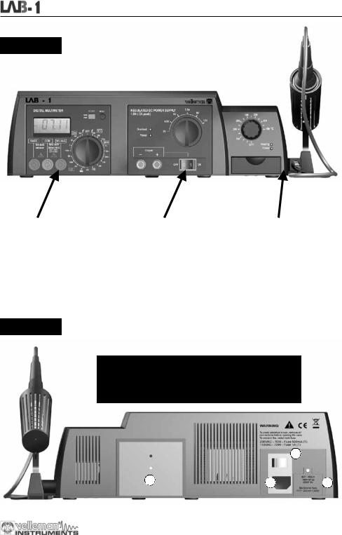
FRONT SIDE
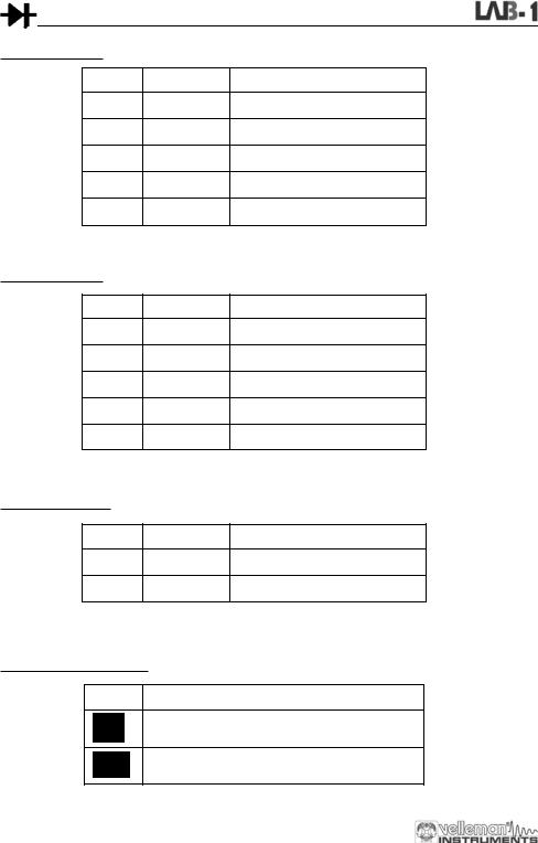
DIGITAL MULTIMETER |
REGULATED POWER SUPPLY |
SOLDERING STATION |
3 1/2 backlit LCD |
Selectable output voltages: |
Low-voltage iron: 24V |
Automatic polarity indication |
3 - 4.5 -6 - 7.5 - 9 - 12Vdc |
Ceramic 48W heating element with |
DC voltage 200mV to 600V in 5 steps |
Output 1.5A (2A peak) |
temperature sensor |
AC voltage 200V and 600V |
LED overload indication |
Temperature range: OFF– 150 -450°C |
DC current 200µA to 10A in 5 steps |
With output on/off switch |
Lead free soldering compatible |
Resistance test 200ohm to 2Mohm |
Very low ripple |
|
Diode, transistor and continuity tester |
LED power indication |
|
Data Hold function and buzzer |
|
|
CATI 600V |
|
|
CATII 300V |
|
|
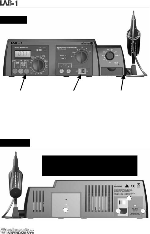
REAR SIDE
1.Mains connector (check if unit complies with your local AC voltage)
2.Mains power switch, this switch provides power to the soldering station and the power supply
3.Multimeter battery compartment (see multimeter unit for more info)
4.Power supply heatsink, caution this plate can get hot.
4 |
|
2 |
|
|
|
|
|
|
|||
1 |
3 |
||||
|
|||||
5
Digital multimeter
 DIGITAL MULTIMETER
SAFETY
1. SAFETY INFORMATION
This multimeter has been designed in accordance with IEC-1010. This norm pertains to electronic measuring instruments that belong to an overvoltage category (CAT II 300V and CAT I 600V)
Follow all safety and operating instructions to ensure that the meter is used safely and is kept in good running order. Full compliance with safety standards can only be guaranteed when the buyer uses the test leads supplied with this packaging. If necessary, they should be replaced with identical leads.
2. SAFETY SYMBOLS
Important safety information, refer to the user manual.
Fuse should be replaced : the rating is specified in the manual.
MAINTENANCE
Before opening the case, always disconnect the test leads from all live circuits.
Avoiding fire risks : respect the specified voltage and current ratings when replacing the fuse (F 200mA / 250V) (Quick acting)
Do not use the device unless all the covers are in place and securely fastened.
Do not apply abrasives or solvents to the meter. Use a damp cloth and mild detergent for cleaning purposes.
DURING USE
Never exceed the limit value for protection. This limit value is listed separately in the specifications for each range of measurement.
Do not touch unused terminals when the meter is linked to a circuit which is being tested.
Never use the meter with category I installations when measuring voltages that might exceed the safety margin of 600V above earth ground.
Set the range selector at its highest position if the intensity of the tension or current to be measured is completely unknown.
Disconnect the test leads from the tested circuit before rotating the range selector in order to change functions. When carrying out measurements on a TV set or switching power circuits, always remember that the meter may be damaged by any high amplitude voltage pulses at test points.
Always be careful when working with voltages above 60Vdc or 30Vac rms. Keep your fingers behind the probe barriers at all times during measurement.
Before attempting to insert transistors for testing, always verify if the test leads have been disconnected. Components should not be connected to the hFE socket while test leads are being used to execute voltage measurements.
Never perform resistance measurements on live circuits.
DESCRIPTION
The device is a battery-operated, 3 ½ digital multimeter for measuring DC and AC voltages, DC current and resistance. It also offers the possibility of executing continuity tests and of testing diodes and transistors.
6
Digital multimeter
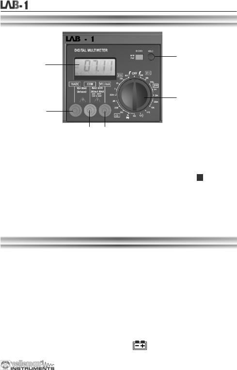
FRONTPANEL
3
1
2
4
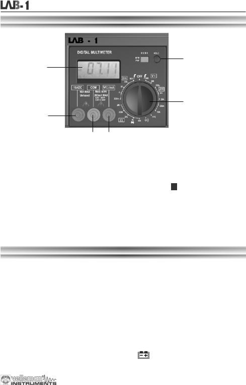
5 6 DESCRIPTION OF THE CONTROL PANEL :
1Display with backlight (the backlight is only on when the complete unit is switched ON at the back) 3 ½ digits, 7 segments, LCD: 15mm high
2Rotary switch
This switch is used to select functions and desired ranges as well as to turn the meter on/off.
3Hold button
Upon pushing this button, the display will retain the last reading and the " |
"-symbol will remain on the |
LCD until the button is pushed again. |
|
4"10A" jack
Insert the red test lead in this connector in order to measure a max. current of 10A.
5"COM" jack
Insert the black (negative) test lead.
6"VΩmA" jack
Insert the red (positive) test lead in this connector to measure voltage, resistance and current (except 10A).
SPECIFICATIONS
Maximum accuracy is achieved during a one-year period after calibration. The ideal set of circumstances requires a temperature of 18 to 28°C (64°F to 82°F) with a maximum relative humidity of 80%.
Maximum voltage between terminals and earth ground |
CAT I 600V or CAT II 300V |
|
Fuse protection |
F 200mA / 250V |
|
Power |
9V battery |
|
Display |
LCD, 1999 counts, updates 2-3/sec. |
|
Measuring method |
Dual-slope integration A/D converter |
|
Overrange indication |
Only figure "1" on the display |
|
Polarity indication |
"-" displayed for negative polarity |
|
Operating temperature |
0 to 40°C |
|
Storage temperature |
-10°C to 50°C |
|
Low battery indication |
" |
" appears on the display |
|
||
7
Digital multimeter
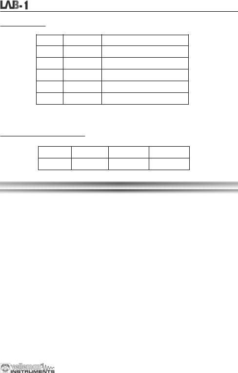
1. DC VOLTAGE
Range |
Resolution |
Accuracy |
|
|
|
200mV |
100µV |
±0.5% of rdg ± 2 digits |
2V |
1mV |
±0.5% of rdg ± 2 digits |
20V |
10mV |
±0.5% of rdg ± 2 digits |
200V |
100mV |
±0.5% of rdg ± 2 digits |
600V |
1V |
±0.8% of rdg ± 2 digits |
Overload protection : 250Vrms for the 200mV range and 600Vdc or rms ac for other ranges.
2. DC CURRENT
Range |
Resolution |
Accuracy |
200µA |
0.1µA |
±1% of rdg ± 2 digits |
2mA |
1µA |
±1% of rdg ± 2 digits |
20mA |
10µA |
±1% of rdg ± 2 digits |
200mA |
100µA |
±1.5% of rdg ± 2 digits |
10A |
10mA |
±3% of rdg ± 2 digits |
Overload protection : F 200mA / 250V fuse. (no fuse for the 10A range).
3. AC VOLTAGE
Range |
Resolution |
Accuracy |
|
|
|
200V |
100mV |
±1.2% of rdg ± 2 digits |
600V |
1V |
±1.2% of rdg ± 2 digits |
Overload protection : 600Vdc or rms ac for all ranges.
Frequency range : 40Hz to 400Hz. Response : average, calibration in rms of a sine wave
4.DIODE & CONTINUITY
Range |
Description |
|
|
If continuity exists (about less that 60Ω), built-in buzzer will sound
Displays the diode's approx. forward voltage drop
Overload protection : 250Vdc or rms ac
8
Digital multimeter
5.RESISTANCE
Range |
Resolution |
Accuracy |
|
|
|
200Ω |
0.1Ω |
±0.8% of rdg ± 2 digits |
2kΩ |
1Ω |
±0.8% of rdg ± 2 digits |
20kΩ |
10Ω |
±0.8% of rdg ± 2 digits |
200kΩ |
100Ω |
±0.8% of rdg ± 2 digits |
2MΩ |
1kΩ |
±1.0% of rdg ± 2 digits |
Maximum open circuit voltage : 3.2V
Overload protection : 250Vdc or rms ac for all ranges.
6.TRANSISTOR hFE TEST (0-1000)
Range |
Tested range |
Tested current |
Tested voltage |
|
|
|
|
NPN & PNP |
0-1000 |
Ib = 10µA |
Vcd = 3V |
OPERATING INSTRUCTIONS
1.DC VOLTAGE MEASUREMENT
1.Connect the red test lead to the "VΩmA" jack and the black lead to the "COM" jack.
2.Set the rotary switch in the desired DCV position. If the voltage to be measured is unknown beforehand, you should set the range switch in the highest range position and then reduce gradually until the ideal resolution is obtained.
3.Connect the test leads to the source being measured.
4.Read the voltage value on the LCD display along with the polarity of the red lead connection.
2.DC CURRENT MEASUREMENT
1.Connect the red test lead to the "VΩmA" jack and the black test lead to the "COM" jack (switch the red lead to the "10A" jack for measurements between 200mA and 10A).
2.Set the rotary switch (DCA) in the desired position.
3.Open the circuit in which the current is to be measured and connect the test leads to the circuit IN SERIES.
4.Read the current value and the polarity of the red lead connection on the LCD display
3.AC VOLTAGE MEASUREMENT
1.Connect the red test lead to the "VΩmA" jack and the black test lead to the "COM" jack.
2.Set the rotary switch in the appropriate ACV position.
3.Connect the test leads to the source to be measured.
4.Read the voltage value on the LCD display.
4.RESISTANCE
1.Connect the red test lead to the "VΩmA" jack and the black test lead to the "COM" jack (the red lead has a positive polarity "+").
2.Set the rotary switch in the appropriate "Ω" range position.
3.Connect the test leads to the resistor to be measured and read the LCD display.
4.If the resistance being measured is connected to a circuit, turn off the power and discharge all capacitors before applying the test probes.
9

Digital multimeter
5. DIODE TEST |
|
|
1. |
Connect the red test lead to "VΩmA" jack and the black one to the "COM" jack (the red lead has a positive |
|
|
polarity "+".). |
|
2. |
Set the rotary switch in the " |
" position. |
3.Connect the red test lead to the anode of the diode to be tested and the black test lead to the cathode of the diode. The approx. forward voltage drop of the diode will be displayed. If the connection is reversed, the display will merely show a "1".
6.TRANSISTOR TEST
1.Set the rotary switch in the "hFE" position.
2.Determine whether the transistor under testing is NPN or PNP and locate the emitter, base and collector leads. Insert the leads into the proper holes of the hFE-socket on the front panel.
3.Read the approximate hFE-value obtained under the following test conditions : a base current of 10µA and Vce 3V.
7.AUDIBLE CONTINUITY TEST
1.Connect the red test lead to "VΩmA" and the black one to "COM".
2.Set the range switch in the "  " position.
3.Connect the test leads to two points of the circuit to be tested. If continuity exists, the built-in buzzer will sound.
BATTERY & FUSE REPLACEMENT
When "  " is displayed, the battery should be replaced.
To replace the battery simply remove the screw at the back of the case, slide out the battery compartment. Remove the old specimen and insert the new one.
Please remember to observe battery polarity.
10
Digital multimeter
When the fuse is blown it will have to be replaced for the device to work again.
Follow the procedure below to replace the protective fuse (200mA / 250V):
Step 1 :
Remove the battery compartment and the screws of the bottom plate (see figure)
Step 2 :
Remove the entire bottom plate.
Step 3 :
Slide out the meter module to facilitate access to the fuse compartment.
Replace the fuse with a similar type 200mA /250V fuse type (quick-acting)
Step 4 :
Slide the meter module back into place, replace the bottom plate and fix it with the screws, then slide the battery compartment back into place.
The unit is now ready for use.
WARNING
Before attempting to open the case, verify if the test leads have been disconnected. Before using the meter, please remember to close the case and tighten the screws properly in order to avoid electroshocks.
11
Regulated power supply
REGULATED POWER
SUPPLY
INTRODUCTION
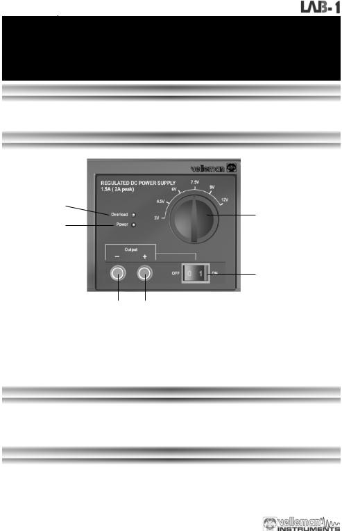
The power unit is a very accurate, DC regulated power supply with a selectable output voltage: 3V, 4.5V, 6V, 7.5V, 9V, 12V. The rated output current is 1.5A and the peak current is 2A.
FRONTPANEL
6
5
2
1
3 4
DESCRIPTION OF THE CONTROL PANEL :
1.Output ON/OFF switch
2.Power indicator
3.Output (-) terminal
4.Output (+) terminal
5.Dial
6.LED overload indication
USE
Turn on the main power switch at the back of the unit; the power indication should lit (2)
Select the output voltage with the dial (5). Connect the positive input terminal of your device with the output (+) terminal (4) and connect the negative input terminal with the output (-) terminal (3).
Using the output ON/OFF switch (1) you can disconnect your application from the power supply.
ATTENTION
The overload LED will lit if the output current exceeds the supply specifications
Do not turn the dial (5) while the device is in use.
12
Soldering station
SOLDERING STATION
INTRODUCTION
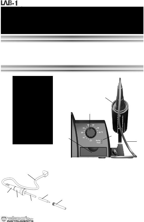
This soldering station is temperature-controlled: sophisticated circuitry regulates the temperature between 150°C and 450°C.
The unit is a 48W soldering station with a temperature sensor in the ceramic heating element. The heating element is supplied with the necessary power via a safe 24V transformer, while the bit is completely isolated from the mains. The control circuitry ensures that devices sensitive to static charges cannot be damaged during the soldering process. The included bit consists of a copper core that is protected by a steel coating.
FRONTPANEL
4
2
7
3
1
 11
11
BEFORE USE, INSERT THE SOLDERING IRON
HOLDER IN THE BASE AND TIGHTEN IT WITH
THE INCLUDED SCREW
|
|
|
|
|
|
|
|
|
|
|
DESCRIPTION OF THE CONTROL PANEL |
|
|
|
|
|
|
|
|
|
|
|
|
|
|
|
|
|
|
1 |
|
|
|
|
|
|
1. |
Heat safe rubber cable |
|
|
|
|
|
|
|
|
|
|
|
||
|
|
|
|
|
|
|
|
|
|
|
2. |
Temperature control |
|
|
|
|
|
|
|
|
|
|
|
3. |
Tray with sponge |
|
|
|
|
|
|
|
|
|
|
|
4. |
Iron stand (fixed to main unit) |
|
|
|
|
|
|
|
|
|
|
|
5. |
Bit |
|
|
|
|
|
|
|
|
|
|
|
6. |
Bit holder |
|
|
|
|
|
|
|
|
5 |
|
|
||
8 |
|
|
|
|
|
|
|
|
|
7. |
Heating indication LED |
|
|
|
|
|
|
|
|
|
|
|
6 |
8. |
Handle |
|
|
9 |
|
|
|
|
|
|
|
|||
|
|
|
||||||||||
|
|
|
|
|
|
|
|
|
|
9. |
Antiskid rubber |
|
|
|
|
|
10 |
|
|
|
|
||||
|
|
|
|
|
|
|
|
|
10. |
Heating element with incorporated temperature |
||
|
|
|
|
|
|
|||||||
|
|
|
|
|
|
|||||||
|
|
|
|
|
|
|
|
|
|
|
|
sensor |
|
|
|
|
|
|
|
|
|
|
|
|
|
|
|
|
|
|
|
|
|
|
|
|
11. |
Power indication LED |
13
Soldering station
WORKING TEMPERATURE
Turn on the complete unit with mains switch on the back, the power indication LED (11) should lit. A well-chosen temperature is essential for efficient soldering. Solder does not flow well when the temperature is too low and this leads to weak soldering. The flux in the solder evaporates when the temperature is too high, not giving the solder sufficient time to flow and possibly damaging the components. The correct temperature and the correct soldering technique practically guarantee a good result. The most common solder alloy consists of 60% of tin (Sn) and 40% of lead (Pb). New lead free solder consists of 99.7% Tin (Sn) and 0.3% Copper (Cu) or 96% Tin (Sn) and 4% Silver (Ag). If the set temperature is rising, the “heating LED” (7) will lit, as soon as the temperature is reached, the LED will blink.
For Lead containing soldering a tip temperature of about 250 to 350°C is recommended. For Lead free soldering a tip temperature between 350 to 400°c is recommended.
It is advisable to use lead containing solder to repair lead containing solderings.
Make sure to turn the temperature control to OFF if the soldering station is not used for long time.
TIPS
ALWAYS KEEP THE SPONGE WET (water only).
Wipe the bit clean before use and keep the tip tinned when the device is not being used. Prolonged use at high temperatures causes the bit to wear prematurely
Never clean the bit with a file or abrasive materials.
Corrosion on the bit can be removed with very fine emery cloth (600 – 800) or with isopropyl alcohol. Heat and tin the bit immediately after cleaning
Remove and clean the bit after 20 hours of usage (or at least once a week) to avoid corrosion Do not use corrosive flux or flux containing chlorine. Resinous flux is safe.
MAINTENANCE
Let the bit cool down before cleaning or replacing it. You can remove the bit by loosening the nut on the bit holder. Clean the bit holder next by blowing into it forcefully. Do not forget to protect your eyes !
Put the bit back in place and tighten the nut. Wipe clean the rest of the iron and the soldering station with a damp cloth. Do not use solvents and make sure no liquid penetrates the housing of the device.
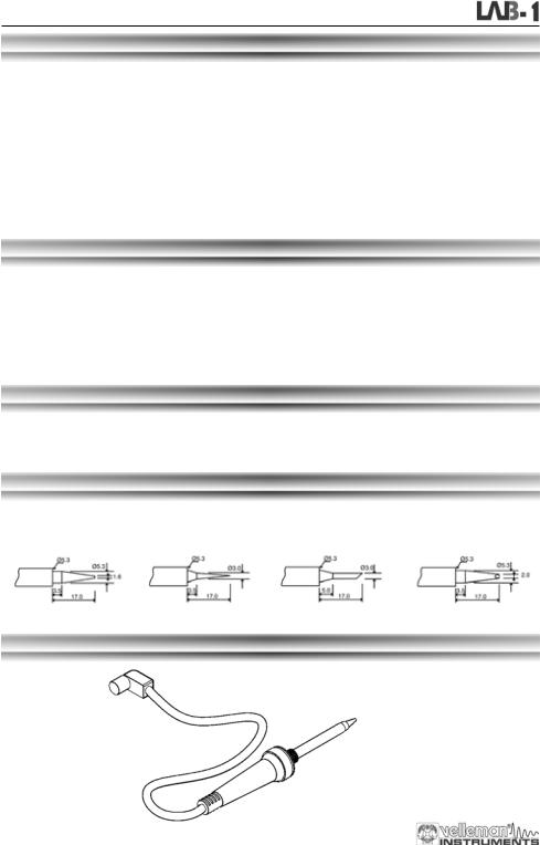
SPARE BITS (size dependant)
BITC10N1 : 1.6mm round BITC10N2 : 0.8mm round |
BITC10N3 : 3.0mm slant- |
BITC10N4 : 2.0mm |
|
edged |
pointed & slant-edged |
||
|
SPARE SOLDERING IRON
LAB1SCS
14

|
Inhoud |
INHOUD |
|
Algemeen .................................................................................................................................................................. |
16 |
In de doos .................................................................................................................................................... |
16 |
Veiligheid & waarschuwingen...................................................................................................................... |
16 |
Waarborg ..................................................................................................................................................... |
16 |
Overzicht van de voorzijde .......................................................................................................................... |
17 |
Overzicht van de achterzijde ....................................................................................................................... |
17 |
Digitale multimeter................................................................................................................................................... |
18 |
Veiligheid...................................................................................................................................................... |
18 |
Onderhoud ................................................................................................................................................... |
18 |
Tijdens gebruik ............................................................................................................................................ |
18 |
Algemene omschrijving................................................................................................................................ |
18 |
Voorzijde ...................................................................................................................................................... |
19 |
Specificaties................................................................................................................................................. |
19 |
Gelijkspanning (DC)................................................................................................. |
20 |
Gelijkstroom (DC)..................................................................................................... |
20 |
Wisselspanning (AC)................................................................................................ |
20 |
Diode & continuiteit .................................................................................................. |
20 |
Weerstand................................................................................................................ |
21 |
Transistor hFE Test (0-1000)................................................................................... |
21 |
Bedieningsinstructies................................................................................................................................... |
21 |
Gelijkspanning meten............................................................................................... |
21 |
Gelijkstroom meten .................................................................................................. |
21 |
Wisselspanning meten ............................................................................................. |
21 |
Weerstand................................................................................................................ |
21 |
Diodentest ................................................................................................................ |
22 |
Transistortest ........................................................................................................... |
22 |
Hoorbare continuiteittest .......................................................................................... |
22 |
Batterij & zekering vervangen...................................................................................................................... |
22 |
Gestabiliseerde voeding ......................................................................................................................................... |
24 |
Inleiding........................................................................................................................................................ |
24 |
Overzicht van de voorzijde .......................................................................................................................... |
24 |
Gebruik......................................................................................................................................................... |
24 |
Opgelet......................................................................................................................................................... |
24 |
Soldeerstation .......................................................................................................................................................... |
25 |
Beschrijving.................................................................................................................................................. |
25 |
Overzicht van de voorzijde .......................................................................................................................... |
25 |
Bedrijfstemperatuur...................................................................................................................................... |
26 |
Tips .............................................................................................................................................................. |
26 |
Onderhoud ................................................................................................................................................... |
26 |
Reservestiften .............................................................................................................................................. |
26 |
Reservesoldeerbout..................................................................................................................................... |
26 |
15

Algemeen
Dank u voor uw aankoop van deze ruimtebesparende laboplossing.
Wij hopen dat dit 3-in-1 toestel u jaren gebruiksgemak zal bezorgen.
In de doos :
LAB1 "3 in 1 LABO toestel"
Testsnoeren voor de digitale multimeter "DMM" Gebruikershandleiding
Spons
Reservestift voor soldeerstation
9V Batterij voor de digitale multimeter "DMM" Netsnoer
LEES DE GEBRUIKS - EN ONDERHOUDSAANWIJZINGEN VAN
DE HANDLEIDING ZORGVULDIG DOOR.
Aan alle ingezetenen van de Europese Unie
Belangrijke milieu-informatie betreffende dit product
Dit symbool op het toestel of de verpakking geeft aan dat, als het na zijn levens-cyclus wordt weggeworpen, dit toestel schade kan toebrengen aan het milieu. Gooi dit toestel (en eventuele batterijen) niet bij het gewone huishoudelijke afval; het moet bij een gespecialiseerd bedrijf terechtkomen voor recyclage. U dient dit toestel naar uw verdeler of naar een lokaal recyclagepunt te brengen. Respecteer de plaatselijke milieuwetgeving.
Heeft u vragen, contacteer dan de plaatselijke autoriteiten inzake afvalverwijdering.
Veiligheid: algemene regels om onze Kits of Modules veilig te gebruiken. Hou rekening met deze aanbevelingen, ze zijn belangrijk voor Uw veiligheid. In geen geval zijn deze richtlijnen kompleet. Vermits de veiligheids vereisten verschillen van plaats tot plaats, dient U ervoor te zorgen dat Uw montage voldoet aan de plaatselijk geldende vereisten. Dit logo staat op toestellen waarin dodelijke spanningen kunnen voorkomen. Wees voorzichtig!
WAARBORG
Dit produkt is gewaarborgd wat betreft gebreken in materialen en vakmanschap op het ogenblik van de aankoop en dit gedurende een periode van TWEE JAAR vanaf de aankoop. De waarborg geldt enkel indien het produkt voorgelegd wordt samen met het origineel aankoop bewijs. De verplichtingen van VELLEMAN N.V. beperken zich tot het herstellen van defecten of, naar vrije keuze van VELLEMAN N.V. tot het vervangen of herstellen van defecte onderdelen. Kosten en risico’s van transport; het wegnemen en terugplaatsen van het produkt, evenals om het even welke andere kosten die rechtstreeks of onrechtstreeks verband houden met de herstelling, worden niet door VELLEMAN N.V. vergoed. VELLEMAN N.V. is niet verantwoordelijk voor schade van gelijk welke aard, veroorzaakt door het falen van een product.
16
General
VOORZIJDE
DIGITALE MULTIMETER |
GESTABILISEERDE VOEDING |
SOLDEERSTATION |
3 ½" LCD met achtergrondverlichting |
Instelbare uitgangsspanning: |
Soldeerbout op lage spanning: 24V |
Automatische polariteitweergave |
3 - 4.5 -6 - 7.5 - 9 - 12Vdc |
Keramisch 48W verwarmingselement |
DC-spanning 200mV tot 600V in 5 |
Uitgang 1.5A (2A piek) |
met temperatuursensor |
stappen |
LED-aanduiding bij overbelasting |
Temperatuurbereik: OFF– 150 -450°C |
AC-spanning 200V en 600V |
Uitgang met on/off schakelaar |
Loodvrij solderen mogelijk |
DC-spanning 200µA tot 10A in 5 |
Zeer lage rimpel |
|
stappen |
LED-aanduiding of het toestel |
|
Weerstandtest 200ohm tot 2Mohm |
ingeschakeld is |
|
Diode-, transistoren continuïteitstest |
|
|
'Data Hold'-functie en buzzer |
|
|
CATI 600V |
|
|
CATII 300V |
|
|
ACHTERZIJDE
1.Netvoeding aansluiting (ga na of uw toestel overeen komt met de lokale AC-spanning)
2.Hoofdschakelaar: deze schakelt het soldeerstation en de voeding in
3.Batterijvak multimeter (zie "multimeter-gedeelte" voor meer informatie)
4.Koelplaat voor de voeding ; let op: deze plaat kan heet worden!
4 |
|
2 |
|
|
|
|
|
|
|||
1 |
3 |
||||
|
|||||
17

Digitale multimeter
DIGITALE
MULTIMETER
VEILIGHEID
1. VEILIGHEIDSVOORSCHRIFTEN
Deze multimeter werd ontworpen in overeenstemming met de IEC-1010-norm. Deze norm heeft betrekking op elektronische meetinstrumenten die tot een overvoltagecategorie (CAT II 300V en CAT I 600V) behoren. Volg nauwgezet alle veiligheidsen bedieningsvoorschriften op. Enkel dan houdt u uw multimeter bedrijfsklaar en kunt u er zeker van zijn dat u hem op een veilige manier gebruikt.
U voldoet enkel aan de veiligheidsvoorschriften indien u de meegeleverde testsnoeren gebruikt. Zo nodig moet u ze vervangen door de identieke snoeren.
2. VEILIGHEIDSSYMBOLEN
Belangrijke info i.v.m. de veiligheid, zie gebruikershandleiding.
Zekering vervangen : het type is vermeld in de handleiding.
ONDERHOUD
Voordat u de behuizing openmaakt, moet u controleren of er nog testsnoeren aangesloten zijn op schakelingen die onder stroom staan.
Vermijden van brandrisico's : respecteer de maximale voltageen stroomniveaus wanneer u de zekering vervangt (F 200mA / 250V - snelwerkend)
Gebruik de meter nooit met open batterijdeksel.
Reinig de meter enkel met een vochtige doek en een zachte detergent. Gebruik nooit agressieve schuurof oplosmiddelen.
TIJDENS GEBRUIK
Overschrijd nooit de grenswaarden. Deze waarden worden telkens apart vermeld in de specificaties van elk meetbereik. Raak geen ongebruikte ingangsbussen aan wanneer de meter gekoppeld is aan een schakeling die u aan het testen bent. Gebruik de meter nooit voor categorie II-installaties wanneer u voltages aan het meten bent die de veiligheidsmarge van 600V boven het massapotentiaal (kunnen) overschrijden.
Zet de bereikregelaar op de hoogste stand als de te meten spanning of stroom helemaal ongekend is.
Koppel de testsnoeren los van de geteste schakeling voordat u een andere functie kiest d.m.v. de keuzeschakelaar. Wanneer u metingen uitvoert op een TV of een schakelende voeding, mag u niet vergeten dat een sterke stroomstoot ter hoogte van de geteste punten de meter kan beschadigen.
Wees uiterst voorzichtig wanneer u werkt met voltages boven 60Vdc of 30Vac rms.Tijdens uw metingen moet u uw vingers te allen tijde achter de meetpennen houden.
Voordat u transistors aansluit om ze te testen, moet u nagaan of alle testsnoeren wel degelijk losgekoppeld zijn. Sluit nooit componenten aan op de hFE-connector terwijl u spanningsmetingen aan het uitvoeren bent d.m.v. testsnoeren.
Voer nooit weerstandsmetingen uit op schakelingen die onder stroom staan. Never perform resistance measurements on live circuits.
ALGEMENE OMSCHRIJVING
Deze module is een batterijgestuurde, handbediende 3 ½-digit digitale multimeter. Met dit apparaat kunt u weerstanden, gelijken wisselspanning en gelijkstroom meten. U kunt continuïteitstesten uitvoeren en u kunt er zelfs dioden en transistors mee testen.
18
Digitale multimeter
VOORZIJDE
3
1
2
4
5 6 BESCHRIJVING VAN HET INSTRUMENTENBORD :
1.Scherm met achtergrondverlichting (de achtergrondverlichting brandt alleen als het hele toestel ingeschakeld is met de schakelaar op de achterkant) 3 ½ digits, 7 segmenten, LCD: 15mm hoog.
2Draaiknop
Wordt gebruikt om de gewenste functie en het bereik in te stellen. Doet ook dienst als voedingsschakelaar (ON/OFF).
3Hold - toets
Wanneer u deze knop indrukt, zal het uitleesvenster de laatste waarde vasthouden. Het " |
" -symbool |
blijft op de LCD tot u de knop opnieuw indrukt. |
|
4"10A" jack
Wanneer u het rode testsnoer aansluit op deze connector, kunt u een max. stroom meten van 10A..
5"COM" jack
Sluit het zwarte (negatieve) testsnoer aan.
6"VΩmA" jack
Sluit het rode (positieve) testsnoer aan op deze connector. U kunt nu spanning, weerstand en stroom meten (uitgez. 10A).
SPECIFICATIES
Tot één jaar na de ijking mag u optimale nauwkeurigheid verwachten.Ideale weersomstandigheden zijn : een temperatuur van 18 tot 28°C met een relatieve vochtigheidsgraad van max. 80%.
Maximale spanning tussen de ingangsbussen en de |
CAT I 600V of CAT II 300V |
||
aarding |
|||
|
|
||
Beveiliging van de zekering |
F 200mA / 250V |
||
Voeding |
9V batterij |
||
Display |
LCD, 1999 punten, updates 2-3/sec. |
||
Meetmethode |
Dual-slope integration A/D convertor |
||
Buiten-bereik indicatie |
Enkel cijfer "1" op de display |
||
Polariteitsindicatie |
"-" op de display (negatieve polariteit) |
||
Werktemperatuur |
0 tot 40°C |
||
Opslagtemperatuur |
-10°C tot 50°C |
||
Batterij-leeg indicatie |
" |
" verschijnt op de display |
|
|
|||
19

Digitale multimeter
1.GELIJKSPANNING (DC)
Range |
Resolution |
Accuracy |
|
|
|
200mV |
100µV |
±0.5% of rdg ± 2 digits |
2V |
1mV |
±0.5% of rdg ± 2 digits |
20V |
10mV |
±0.5% of rdg ± 2 digits |
200V |
100mV |
±0.5% of rdg ± 2 digits |
600V |
1V |
±0.8% of rdg ± 2 digits |
Beveiliging tegen overbelasting : 250Vrms voor het 200mV-bereik en 600Vdc of rms ac voor elk ander bereik.
2.GELIJKSTROOM (DC)
Bereik |
Resolutie |
Nauwkeurigheid |
200µA |
0.1µA |
±1% uitlezing ± 2 digits |
2mA |
1µA |
±1% uitlezing ± 2 digits |
20mA |
10µA |
±1% uitlezing ± 2 digits |
200mA |
100µA |
±1.5% uitlezing ± 2 digits |
10A |
10mA |
±3% uitlezing ± 2 digits |
Beveiliging tegen overbelasting : F 200mA / 250V zekering. (geen zekering voor het 10A-bereik).
3.WISSELSPANNING (AC)
Bereik |
Resolutie |
Nauwkeurigheid |
|
|
|
200V |
100mV |
±1.2% uitlezing ± 2 digits |
600V |
1V |
±1.2% uitlezing ± 2 digits |
Beveiliging tegen overbelasting : 600Vdc of rms ac voor elk bereik.
Frequentiebereik : 40Hz tot 400Hz. Respons : gemiddeld, ijking in rms van de sinuslijn.
4.DIODE & CONTINUITEIT
Bereik |
Omschrijvingn |
|
|
Als er continuïteit is (<60Ω), gaat de ingebouwde buzzer af
Op de display verschijnt het voorwaartse spanningsverlies van de diode
Beveiliging tegen overbelasting : 250Vdc of rms ac
20
 Loading...