


DVM 850BL
USER MANUAL GEBRUIKERSHANDLEIDING NOTICE D’EMPLOI MANUAL DEL USUARIO BEDIENUNGSANLEITUNG INSTRUKCJA OBSŁUGI
ENGLISH
T o all residents of the European Union
Important environmental inform ation abo ut this pro duct
This symbol on the device or the pack age indicates that disposal of the device afte r its lifecyc le could harm the environment.
Do not dispose of the unit (or batteries) as unsorted municipal waste; it should be taken to a specialised company for recycling.
T his device should be returned to your distributor or to a local recycling service . R espect the local envir onmental ru les.
If in doubt, contact your local w aste disposal authorities.
1. SAFETY
1.1. SAF ETY IN FORM ATION
This multimeter has been designed in accordanc with EN61010-1: 2001. Thi s norm pertains to electron ic measur ing instruments tha t emit pollution 2 and belong to an ov ervoltage
c ategory (CAT II).
F ollow all safety and operatin g instructions to ensure that the meter is used safely and is kept in good running order.
F ull compliance with safety standards c an only be guaranteed when the buyer uses the test leads supplied with this packa ging. If necessary, they should be replaced with identical leads.
1.2. SAF ETY S YMBOLS
Im portant safety information, refer to th e user ma nual.
Dangerous voltage is possible.
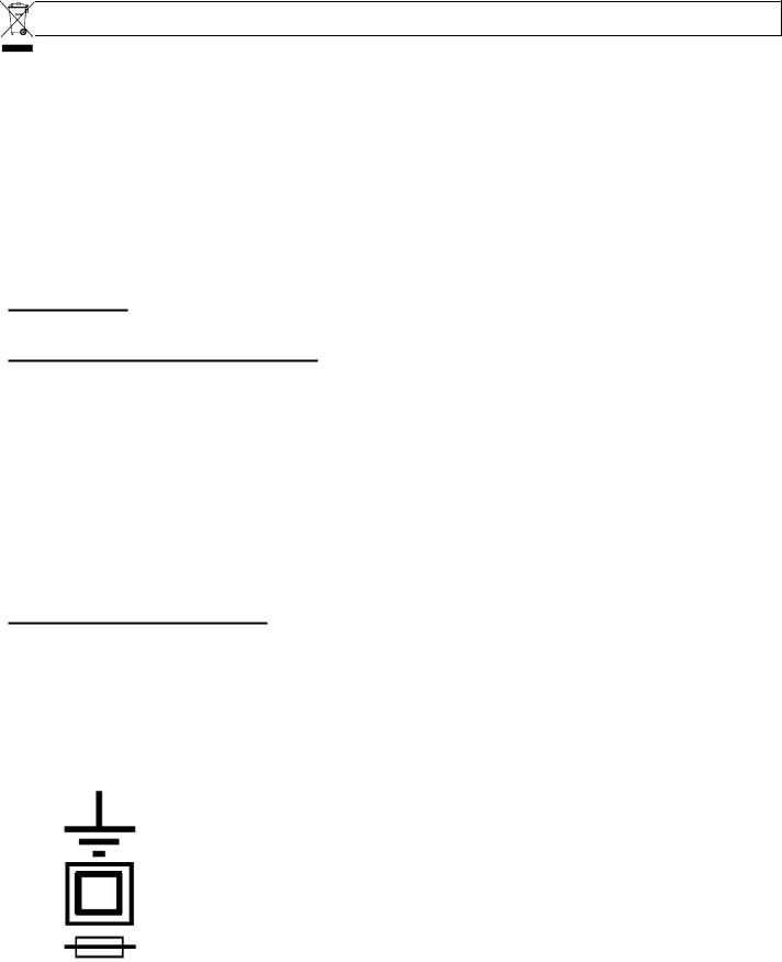
E arthing.
Double ins ulation (class II-protection)
Re place a blown fuse by a fuse with the same ratin gs as specified in this manual.
2. MAINTENANCE
•Before opening the case, always disconnect the test leads from all live circuits.
•Avoiding fire risks : respect the specified voltage and current ratings when replacing the fuse.
F 500mA / 250V, 10A / 250V (Quick acting)
•Do not use the device unless the back cover is in place and securely fastened.
•Do not apply abrasives or solvents to the meter. Use a damp cloth and mild detergent for cleaning purposes.
3. DURING USE
•Never exceed the limit value for protection. This limit value is listed separately in the specifications for each range of measurement.
•Do not touch unused terminals when the meter is linked to a circuit which is being tested.
•Never use the meter with category II installations when measuring voltages that might exceed the safety margin of 600V above earth ground.
•Set the range selector at its highest position if the intensity of the charge to be measured is unknown beforehand.
•Disconnect the test leads from the tested circuit before rotating the range selector in order to change functions.
•When carrying out measurements on a TV set or switching power circuits, always remember that the meter may be damaged by any high amplitude voltage pulses at test points.
•Always be careful when working with voltages above 60Vdc or 30Vac rms. Keep your fingers behind the probe barriers at all times during measurement.
•Before attempting to insert transistors for testing, always verify if the test leads have been disconnected.
•Components should not be connected to the hFE socket while test leads are being used to execute voltage measurements.
•Never perform resistance measurements on live circuits.
4. GENERAL DESCRIPTION
The device is a battery-operated, hand-held 3 ½ digital multimeter for measuring DC and AC voltages, DC current and resistance. It also offers the possibility of executing continuity tests and of testing diodes and transistors. The back light is optional.

4.1. FRONT PANEL

4.2. FR ONT PANEL DE SCRIPTION
cDisplay
3 ½ digits, 7 segments, L CD : 15m m high
d Back light
When this button is pushed, the back light will illuminate your display for approximately 5 seconds.
e Rotary switch
This s witch is u sed to sele ct functio ns and desired rang es as well as to turn the mete r on/off.
f Hold b utton
Upon pushing th is button, the display will re ain the last reading and the " "-sym bol will remain on the LCD until the bu tton is pushed again.
g "10A" jack
Insert the red tes t lead in this connector in or der to me asure a m ax. current of 10A.
h"COM" jack
Insert the black (negative ) test lead .
i"VΩmA" jack
Insert the red (positive) test lead in this conn ector to measure voltage, resistance and current (except 10A).
5. SPEC IFICATIONS
Maximum accuracy is achieved during a one-yea r period a fter calib ration. The ideal se t of
c ircumsta nces requires a tem perature of 18 to 28°C (64°F to 82°F) with a ma ximum relative h umidity o f 80%.
Maximum voltage between ter minals and earth ground |
CAT II 600V |
|
Fuse protection |
F 500 mA / 250V, 10A / 250V |
|
P ower |
9V ba ttery |
|
Display |
LCD, 1999 co unts, updates 2-3/sec. |
|
Measuring method |
Dual-slope integration A/D conve rter |
|
Overrange indication |
Only figure "1" on the display |
|
P olarity indication |
"-" displayed f or negative polarity |
|
Operating temperat ure |
0 to 40°C |
|
S torage temperature |
-10°C to 50°C |
|
Low battery indicati on |
" |
" appears on the display |
Dimensio ns |
138 x 69 x 31m m |
|
Weight |
Appr ox. 142g |
|

5.1. DC VOLTAGE
Range |
Resolution |
Acc uracy |
|
200mV |
100 |
µV |
±0.5% of r dg ± 2 digits |
2V |
1m |
V |
±0.8% of r dg ± 2 digits |
20V |
10 mV |
±0.8% of r dg ± 2 digits |
|
200V |
100mV |
±0.8% of r dg ± 2 digits |
|
600V |
1V |
±1.0% of r dg ± 2 digits |
|
Overload protection : 250Vrm s for the 200mV ra nge and 6 00Vdc or rms ac f or other ranges.
5.2. DC CURRE NT
Range |
Resolution |
Acc uracy |
200ùA |
0.1µA |
±1% of rdg ± 2 digits |
2mA |
1µ A |
±1% of rdg ± 2 digits |
20mA |
10µA |
±1% of rdg ± 2 digits |
200mA |
100 µA |
±1.5% of r dg ± 2 digits |
10A |
10 mA |
±3% of rdg ± 2 digits |
Overload protection : F 500mA / 250V, 10A / 250V fuse.
5.3. AC VOLTAGE
Range |
Resolution |
Acc uracy |
200V |
100mV |
±1 .2% of rdg ± 10 di gits |
600V |
1V |
±1 .2% of rdg ± 10 di gits |
Overload protection : 600Vdc or rms a c for all ra nges.
F requency range : 40Hz to 400Hz. Response : av erage, cal ibration in rms of a sine wave.
5.4. DIODE & CONTIN UITY
Range |
De scription |
|||
|
|
|
If contin uity exists (less than |
60Ω), bu ilt-in buzzer will s ound |
|
|
|
|
|
|
|
|
Dis plays the diode's a |
prox. forward volt age drop |
|
|
|
|
|
Overload protection : 250Vdc or rms a c

5.5. RESISTANCE
Range |
Resolution |
Accuracy |
200Ω |
0.1Ω |
±0.8% of rdg ± 2 digits |
2kΩ |
1Ω |
±0.8% of rdg ± 2 digits |
20kΩ |
10Ω |
±0.8% of rdg ± 2 digits |
200kΩ |
100Ω |
±0.8% of rdg ± 2 digits |
2MΩ |
1kΩ |
±1.0% of rdg ± 2 digits |
Maximum open circuit voltage : 3.2V
Overload protection : 250Vdc or rms ac for all ranges.
5.6. TRANSISTOR hFE TEST (0-1000)
Range |
Tested range |
Tested current |
Tested voltage |
NPN & PNP |
0-1000 |
Ib = 10µA |
Vcd = 3V |
6. OPERATING INSTRUCTIONS
6.1. DC VOLTAGE MEASUREMENT
1.Connect the red test lead to the "VΩmA" jack and the black lead to the "COM" jack.
2.Set the rotary switch in the desired DCV position. If the voltage to be measured is unknown beforehand, you should set the range switch in the highest range position and then reduce gradually until the ideal resolution is obtained.
3.Connect the test leads to the source being measured.
4.Read the voltage value on the LCD display along with the polarity of the red lead connection.
6.2. DC CURRENT MEASUREMENT
1.Connect the red test lead to the "VΩmA" jack and the black test lead to the "COM" jack (switch the red lead to the "10A" jack for measurements between 200mA and 10A).
2.Set the rotary switch (DCA) in the desired position.
3.Open the circuit in which the current is to be measured and connect the test leads to the circuit IN SERIES.
4.Read the current value and the polarity of the red lead connection on the LCD display

|
6.3. AC VOLTAGE ME ASURE MENT |
|
1 |
. Connect the red test lead to the "VΩmA" jack and the black test lead to the "COM" jack. |
|
2 |
. Set the rotary switch in the appropria te ACV p osition. |
|
3 |
. Connect the test leads to the source to be meas ured. |
|
4 |
. Read the voltage value on t he LCD d isplay. |
|
6.4.RE SISTANCE
1. Connect the red test lead to the "VΩmA" jack and the black test lead to the "COM" jack (the red lead has a positive polarity "+").
2. Set the rotary switch in the appropria te "Ω" range position.
3. Connect the test leads to the resistor to be measured and read the LCD display.
4. If the resistance b eing measured is c onnected to a circuit, turn off the power and discharge all capacitors bef ore applying the test probes.
6.5.DIODE TE ST
1 |
. Connect the red test lead to "VΩmA" jack and the black one to the "COM" jack (the red |
|
|
lead has a positive polarity "+".). |
|
2 |
. Set the rotary switch in the " |
" position. |
3 |
. Connect the red test lead to the anode of the di ode to be tested an d the black test lead to |
|
|
the cathode of the diode. The approx. forward voltage drop of the diode will be displayed. |
|
|
If the co nnection is reversed, the dis play will merely sh ow a "1". |
|
|
6.6. TRA NSISTOR TES T |
|
1 |
. Set the rotary switch in the "hFE" position. |
|
2 |
. Determ ine whether the tran sistor un der testing is NPN o r PNP and locate t he emitter, base |
|
|
and collector lead s. Insert the leads into the proper hole s of the hF E-socket on the fro nt |
|
|
panel. |
|
3 |
. Read the approxi mate hFE-value obtained und er the following te st conditio ns : a base |
|
|
current of 10µA a nd Vce 3V. |
|

6.7. AU DIBLE C ONTINUITY T EST
1 |
. Connect the red test lead to "VΩmA" and the black one to "COM". |
||
2 |
. Set the range switch in the " " pos ition. |
||
3 |
. Connect the test leads to tw o points of the circuit to be tested. If continuity exists, th e |
||
|
built-in buzzer w ill sound. |
||
|
7. BATTERY & FUSE R EPLAC EMEN T |
|
|
|
When" |
" is displayed, the battery sh ould be r eplaced. |
|
F uses rarely need replacement and blo wn fuses almost alw ays result from hu man error.
To replace the battery or fuse (F 500m A / 250V, 10A / 25 0V), simply remove the 2 screws a t the back of the case. Remove the old specimen and insert the new one.
P lease rem ember to observe b attery po larity.
8. WAR NING
Before att empting t o open the case, verify if the test leads have been disconne cted. Before u sing the meter, please remem ber to cl ose the case and tighten the screws properly in order to avoid electroshocks.
9.ACCE SSORIES
•User m anual
•Set of te st leads
•Gift box
•9V batt ery
•Holster

NE DERLANDS
Aan alle ingezetenen van de Europese Unie
Belangrijk e milieu-informatie b etreffend e dit produ ct
Dit s ymbool op het toestel of de verpakking gee ft aan dat, als het na zijn levens cyclus wordt wegg eworpen, dit toestel schade kan toebreng en aan het milieu.
Gooi dit toestel (en eventu ele batterijen) niet bij het gewon e huishou delijke afva l; het moet bij e en gespec ialiseerd bedrijf terechtkomen voor recycla ge.
U moet dit toestel naar uw verdeler of naar een lokaal recyclage punt brengen. Respecteer de plaats lijke milieu wetgeving.
Heeft u vra gen, contacteer dan de plaats elijke aut oriteiten in zake verw ijdering.
1. VEILIGHEID
1.1. VEILIGHEI DSVOORSCHR IFTEN
Deze multimeter werd ontwor pen in overeenstem ming met d e EN61010-1:2001 -norm. Deze
n orm heeft betrekkin g op elektronische meetinstrumenten die norm 2-vervuiling uitstoten en tot e en overvo ltagecateg orie (CA T II) beho ren.
Volg nauw gezet alle veiligheid s- en bed ieningsvo orschriften op. Enkel dan houd t u uw multimeter bedrijfsklaar en kunt u er zeker van zij n dat u he m op een v eilige manier gebruikt. U voldoet enkel aan de veiligheidsvoors chriften indien u de meegelev erde testsnoeren gebruikt. Zo nodig moet u ze vervangen door de i dentieke s noeren.
1.2. VEILIGHEI DSSYMBOLEN
Belangrijke info i.v.m . de veiligheid, zie gebruikershandlei ding.
Gevaarlijk voltage mogelijk.
Aarding.
Dubbele iso latie (klasse II-bes cherming)
V ervang ee n doorgeslagen zekering doo r een zekering met dezelfde w aarden als vermeld in deze ha ndleiding.
2. ONDERHOUD
•Voordat u de doos openmaakt, moet u controleren of er nog testsnoeren aangesloten zijn op schakelingen die onder stroom staan.
•Vermijden van brandrisico's : respecteer de maximale voltageen stroomniveaus wanneer u de zekering vervangt.
F 500mA / 250V, 10A / 250V (snelwerkend)
•Gebruik de meter nooit met open batterijdeksel.
•Reinig de meter enkel met een vochtige doek en een zachte detergent. Gebruik nooit agressieve schuurof oplosmiddelen.
3. GEBRUIK
•Overschrijd nooit de grenswaarden. Deze waarden worden telkens apart vermeld in de specificaties van elk meetbereik.
•Raak geen ongebruikte ingangsbussen aan wanneer de meter gekoppeld is aan een schakeling die u aan het testen bent.
•Gebruik de meter nooit voor categorie II-installaties wanneer u voltages aan het meten bent die de veiligheidsmarge van 600V boven het massapotentiaal (kunnen) overschrijden.
•Plaats de bereikschakelaar in de hoogste stand indien u de intensiteit van de belasting niet op voorhand kent.
•Koppel de testsnoeren los van de geteste schakeling voordat u een andere functie kiest d.m.v. de keuzeschakelaar.
•Wanneer u metingen uitvoert op een TV of een schakelende voeding, mag u niet vergeten dat een sterke stroomstoot ter hoogte van de geteste punten de meter kan beschadigen.
•Wees uiterst voorzichtig wanneer u werkt met voltages boven 60Vdc of 30Vac rms.Tijdens uw metingen moet u uw vingers te allen tijde achter de meetpennen houden.
•Voordat u transistors aansluit om ze te testen, moet u nagaan of alle testsnoeren wel degelijk losgekoppeld zijn.
•Sluit nooit componenten aan op de hFE-connector terwijl u spanningsmetingen aan het uitvoeren bent d.m.v. testsnoeren.
•Voer nooit weerstandsmetingen uit op schakelingen die onder stroom staan.
4. ALGEMENE OMSCHRIJVING
De DVM850 is een batterijgestuurde, handbediende 3 ½ digitale multimeter. Met dit apparaat kunt u weerstanden, gelijken wisselspanning en gelijkstroom meten. U kunt continuïteitstesten uitvoeren en u kunt er zelfs dioden en transistors mee testen. Het achtergrondlichtje is optioneel.

4.1. INSTRUMENTENBORD

4.2. BE SCHRIJVING VAN HET INSTR UMEN TENBO RD
cDisplay
3 ½ digits, 7 segmenten, LCD : 15 mm hoog
d |
Achtergrondlichtje |
|
Een druk op deze knop doet uw display gedure nde ongeveer 5 seconden oplichten. |
e |
Draaiknop |
|
Wordt gebruikt om de ge wenste fu nctie en h et bereik in te stellen. Doet o ok dienst als |
|
voedin gsschake laar (ON/ OFF). |
fHold-toets
Wanne er u deze knop indrukt, zal h et uitlees venster de laatste waarde vasthouden. Het "
 "-sy mbool blijft op de LCD tot u de knop opnieuw indrukt.
g"10A" jack
Wanne er u het rode testsnoer aansl uit op deze connect or, kunt u een max. stroom m eten
van 10A.
h"COM" jack
Sluit het zwarte (negatieve) testsnoer aan.
i"VΩmA" jack
Sluit het rode (positieve) testsnoer aan op de ze connector. U kun t nu spanning, weerstand en stroom mete n (uitgez. 10A).
5. SPEC IFICATIES
Tot één ja ar na de ijking mag u optimal e nauwkeurigheid verwachten.Ideale weersoms tandigheden zijn : een tempe ratuur van 18 tot 28°C met een relatie ve v ochtigheidsgraad van max. 8 0%.
Maximale spanning tussen de in gangsbussen en de a arding
Beveiliging van de zekering Voeding
Display Meetmethode
Buiten-ber eik indica tie P olariteitsindicatie Werktemperatuur Opslagtem peratuur Batterij-leeg indicatie
Afmetinge n Gewicht
CAT II 600V
F 500 mA / 250V, 10A / 250V 9V ba tterij
LCD, 1999 pu nten, upda tes 2-3/se c. Dual-slope integration A/D conve rtor Enkel cijfer "1 " op de di splay
"-" op de displa y (negatieve polariteit) 0 tot 40°C
-10°C tot 50°C
" " verschijnt op de display 138 x 69 x 31m m
Ongeveer 142g

5.1. GE LIJKSP ANNING
Bereik |
Reso lutie |
Nauwke urigheid |
|
200mV |
100 |
µV |
±0 .5% uitlezing ± 2 digits |
2V |
1m |
V |
±0 8% uitlezing ± 2 digits |
20V |
10 mV |
±0 8% uitlezing ± 2 digits |
|
200V |
100mV |
±0 8% uitlezing ± 2 digits |
|
600V |
1V |
±1 0% uitlezing ± 2 digits |
|
Beveiliging tegen o verbelasting : 250Vrms voor het 200mV-bereik en 600Vdc of rms a c v oor elk a nder bereik.
5.2. GE LIJKST ROOM
Bereik |
Reso lutie |
|
Nauwke urigheid |
200ùA |
0.1µA |
± |
1% uitlezing ± 2 dig its |
2mA |
1µ A |
± |
1% uitlezing ± 2 dig its |
20mA |
10µA |
± |
1% uitlezing ± 2 dig its |
200mA |
100 µA |
±1 |
.5% uitlezing ± 2 digits |
10A |
10 mA |
± |
3% uitlezing ± 2 dig its |
Beveiliging tegen overbelasting : F 500 mA / 250V , 10A / 250V.
5.3. WIS SELSPANNIN G
Bereik |
Reso lutie |
Nauwke urigheid |
200V |
100mV |
±1. 2% uitlezi ng ± 10 digits |
600V |
1V |
±1. 2% uitlezi ng ± 10 digits |
Beveiliging tegen o verbelasting : 600Vdc of rms ac voor elk bereik.
F requentie bereik: 4 0Hz tot 40 0Hz. Respons: gem iddeld, ijking in rm s van de sinuslijn.
5.4. DIODE & CONTIN UITEIT
Bereik |
Oms chrijving |
|
Als er continuïteit is (<60Ω), gaat de ingebou wde buzzer af |
|
|
|
Op d e display verschijnt het voorwaartse s panningsv erlies van de diode |
|
|
Beveiliging tegen o verbelasting : 250Vdc of rms ac

5.5. WEERSTAND
Bereik |
Resolutie |
Nauwkeurigheid |
200Ω |
0.1Ω |
±0.8% uitlezing ± 2 digits |
2kΩ |
1Ω |
±0.8% uitlezing ± 2 digits |
20kΩ |
10Ω |
±0.8% uitlezing ± 2 digits |
200kΩ |
100Ω |
±0.8% uitlezing ± 2 digits |
2MΩ |
1kΩ |
±1.0% uitlezing ± 2 digits |
Max. spanning open schakeling : 3.2V
Beveiliging tegen overbelasting : 250Vdc of rms ac voor elk bereik.
5.6. TRANSISTOR hFE TEST (0-1000)
Bereik |
Testbereik |
Teststroom |
Testspanning |
NPN & PNP |
0-1000 |
Ib = 10µA |
Vcd = 3V |
6. BEDIENINGSINSTRUCTIES
6.1. GELIJKSPANNING METEN
1.Verbind het rode testsnoer met de "VΩmA"-aansluiting en het zwarte testsnoer met de "COM"-aansluiting.
2.Stel het gewenste meetbereik in d.m.v. de draaiknop. Stel de functieschakelaar in op het grootste bereik indien de te meten gelijkspanning niet vooraf gekend is en verminder dan geleidelijk om de ideale resolutie te bepalen.
3.Verbind de meetsnoeren met de schakeling.
4.U kunt nu de intensiteit van de spanning en de polariteit van het rode testsnoer aflezen op de LCD-display.
6.2. GELIJKSTROOM METEN
1.Verbind het rode testsnoer met de "VΩmA"-aansluiting en het zwarte testsnoer met de "COM"-aansluiting (stop het rode snoer in de "10A"-aansluiting voor metingen tussen 200mA en 10A).
2.Stel het gewenste meetbereik in d.m.v. de draaiknop (DCA).
3.Verbind de meetsnoeren IN SERIE met de schakeling waarvan u de belasting wilt meten.
4.U kunt nu de stroomwaarde en de polariteit van het rode meetsnoer aflezen op de LCDdisplay.

6.3.WIS SELSPANNIN G METE N
1. Verbind het rode testsnoer met de "V ΩmA"-a ansluiting en het zw arte testsnoer met de "COM"-aansluiti ng.
2 |
. Stel het gewenste meetbereik in d.m.v. de draa iknop (ACV). |
3 |
. Verbind de meetsnoeren met de schakeling. |
4 |
. Lees de intensiteit van de spanning af op de L CD-displa y. |
|
6.4. WEERSTAND |
|
1 |
. Verbind het rode testsnoer met de "V ΩmA"-a ansluiting en het zw arte testsnoer met de |
|
|
"COM"-aansluiti ng (het rode snoer h eeft een p ositieve p olariteit"+"). |
|
2 |
. Plaats de functieschakelaar in de gew enste stand ("Ω"). |
|
3 |
. Verbind de meetsnoeren met de weerstand en lees de L CD-display. |
|
4 |
. Zorg er voor dat bij weerstandsmetingen geen spanning meer op de schakeling staat e n dat |
|
|
alle condensatoren volledig ontladen zijn. |
|
6.5. DIODETEST
1 |
. Verbind het rode testsnoer met de "V ΩmA"-a ansluiting en het zw arte testsnoer met de |
||
|
"COM"-aansluiti ng (het rode snoer h eeft een p ositieve p olariteit"+"). |
||
2 |
. Plaats de functieschakelaar in de gew enste stand (" |
"). |
|
3 |
. Verbind het rode meetsnoer met de a node van de diode in kwesti e en verbind het zwarte |
||
|
meetsno er met de kathode van de dio de. Het voorwaarts e spanningsverlies van de diode |
||
|
verschijnt nu op u w displa y. Wordt d e schakeling omgedraaid, dan verschi jnt enkel het |
||
|
cijfer "1 " op uw d isplay. |
|
|
|
6.6. TRA NSISTORTEST (hFE-TEST) |
|
|
1 |
. Plaats de functieschakelaar in de "hF E"-stand. |
|
|
2 |
. Bepaal of het om een NPNof PNP-transistor gaat en lo kaliseer d e zender, de basis e n de |
||
|
collector. Stop de snoeren i n de overeenkomstige openi ngen van de hFE-co nnector op het |
||
|
frontpa neel. |
|
|
3 |
. Lees de benaderende hFEwaarde op uw display. Testo mstandigh eden : ba sisstroom van |
||
|
10µA e n een collector-emitterspanning (Vce) van 3V. |
|
|
 Loading...