


DVM68
3 ¾ DMM WITH AUTORANGE / BARGRAPH / FREQUENCY
3 3/4-DIGIT DMM MET AUTOMATISCHE BEREIKINSTELLING / BARGRAPH / FREQUENTIEMETING
MULTIMÈTRE NUMÉRIQUE 3 ¾ AVEC SÉLECTION DE PLA GE AUTOMATIQUE / BARGRAPH / FRÉQUENCE
MULTÍMETRO 3 ¾ DÍGITOS CON RANGO AUTOMÁTICO / BARRA GRÁFICA / FRECUENCÍMETRO
3 ¾-STELLIGES DIGITALMULTIMETER MIT AUTO RANGE / BALKENGRAFIK / FREQUENZMESSUNG
USER MANUAL |
3 |
GEBRUIKERSHANDLEIDING |
12 |
NOTICE D’EMPLOI |
23 |
MANUAL DEL USUARIO |
33 |
BEDIENUNGSANLEITUNG |
43 |

DVM68 |
Rev. 01 |
25.02.2011 |
2 |
©Velleman nv |
DVM68 |
Rev. 01 |
User manual
1. Introduction
To all residents of the European Union
Important environmental information about this product
This symbol on the device or the package indicates that disposal of the device after its lifecycle could harm the environment. Do not dispose of the unit (or batteries) as unsorted municipal waste; it should be taken to a specialized co mpany for recycling. This device should be returned to your distributor or to a local recycli ng service. Respect the local environmental rules.
If in doubt, contact your local waste disposal authorities.
Thank you for choosing Velleman! Please read the manual thoroughly before bringing this device into service. If the device was damaged in transit, don't install or use it and contact your dealer.
Your DVM68 is a autoranging professional digital multimeter with a 3 ¾ digit LCD display. It is ideally suited for field, lab, shop, and home applications. By using the latest in IC and display technology to significantly reduce the number of discrete internal compone nts, the multimeter gives you superb measuring capability as well as the highest possible reliability.
It is capable of performing functions : |
|
|
DC Voltage |
AC Voltage |
Resistanc e |
AC Current |
DC Current |
Capacity |
Frequency |
Continuity |
|
Also diodes and transistors (amplification hFE) can be tested.
Use extreme caution in the use of this device. Improper use of this device can result in injury or death. Follow all safeguards suggested in this owner's manual in addition to normal safety precautions in dealing with electrical circuits. Do not use this device if you are unfamiliar with electrical circuits and testing procedures.
Not for commercial or industrial use.
Refer to the Velleman® Service and Quality Warranty on the last pages of this manual.
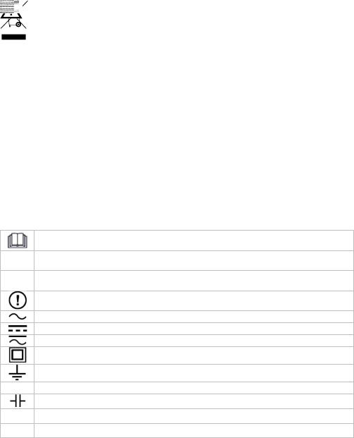
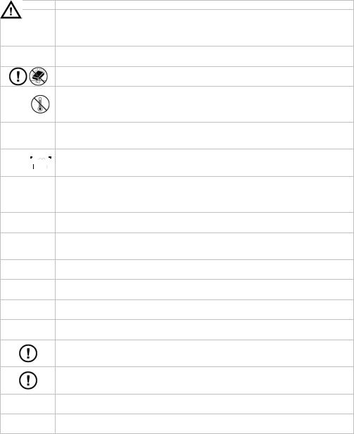
2. Used symbols
This symbol indicates: Read instructions
Not reading the instructions and manual can lead to damage, inj ury or death.
This symbol indicates: Danger
A hazardous condition or action that may result in injury or death
This symbol indicates: Risk of danger/damage
Risk of a hazardous condition or action that may result in damage, injury or death
This symbol indicates: Attention; important information
Ignoring this information can lead to hazardous situations.
AC (Alternating Current)
DC (Direct Current)
Both AC and DC
Double insulation (class II-protection)
Earth
 Fuse
Fuse
Capacitor
Diode
Continuity
25.02.2011 |
3 |
©Velleman nv |

DVM68 |
Rev. 01 |
3. Safety Instructions
Read this manual thoroughly. Familiarise yourself with the fu nctions of the device before actually using it.
Only use the device for its intended purpose. Using the device in an unauthorized way will void the warranty. Damage caused by disregard of certain guidelines in this manual is not covered by the warranty and the dealer will no t accept responsibility for any ensuing defects or problems.
Follow the instructions below to guarantee a safe use of the meter and all its functionalities.
During use of the meter, respect all directives concerning pro tection against electroshocks and misuse. Never exceed the indicated limits.
WARNING: To avoid electrical shock always disconnect the test leads prior to opening the housing.
Remark: refer to the warning on the back of the meter
WARNING: To prevent fire, use exact fuses.
Remark: refer to the warning on the back of the meter
Keep the device away from children and unauthorised users.

 Protect this device from shocks and abuse. Avoid brute force when operating.
Avoid cold, heat and large temperature fluctuations. When the unit is moved from a cold to a warm location, leave it switched off until it has reached room temperature. This to avoid condensation and measuring errors.
This is an installation category CAT III 600V / CAT II 1 000V measuring instrument. Never use this equipment in a higher category than indicated. Refer to
§4 Overvoltage /installation category.
Pollution degree 2-device. For indoor use only. Keep this device away from rain, 


 moisture, splashing and dripping liquids. Not for industrial use. Refer to §5


 Pollution degree.
Before each use, make sure the test probes are in good cond ition. Always place your fingers behind the protective edges of the test probes while measuring! Never touch free terminals when the meter is connected to a circuit.
Make sure the meter is in the appropriate measuring range b efore connecting it to a test circuit.
Risk of electric shock during operation. Be very careful w hen measuring live circuits. Use extreme caution when measuring voltages highe r than 60Vdc or 30Vac rms.
Do not measure circuits that may contain voltages > 1000V
Do not measure current in circuits with voltages > 250V
Do not conduct resistance, diodeor continuity measurements on live circuits.
When measuring currents above 5A, max. 15s continuous measurement followed by a 10 minutes break between 2 measurements.
When carrying out measurements on a TV set or switching power circuits, always be aware that high amplitude voltage pulses at the test points m ight damage the meter.
Do not replace internal parts yourself. Replace damaged or lost accessories by identical ones with the same specifications. Order spare acce ssories e.g. test probes at your dealer.
25.02.2011 |
4 |
©Velleman nv |

DVM68 |
Rev. 01 |
Switch off the meter and remove test probes prior to replacing the battery or fuses.
All modifications of the device are forbidden for safety reasons. Damage caused by user modifications to the device is not covered by the warra nty.
4. Overvoltage/installation category
DMMs are categorized depending on the risk and severity of transient overvoltage that might occur at the point of test. Transients are short-lived bursts of energy induc ed in a system, e.g. caused by lightning strike on a power line.
The existing categories according EN 61010-1 are:
CAT I |
A CAT I-rated meter is suitable for measurements on protected electronic circuits which |
are not directly connected to mains power, e.g. electronics circuit s, control signals… |
|
|
A CAT II-rated meter is suitable for measurements in CAT I-envir onments and mono- |
CAT II |
phase appliances which are connected to the mains by means of a plug and circuits in a |
normal domestic environment, provided that the circuit is at least 10m apart from a CAT |
|
|
IIIor 20m apart from a CAT IV-environment. E.g. household appliances, portable tools… |
|
A CAT III-rated meter is suitable for measurements in CAT I- and CAT II-environments, |
CAT III |
as well as for measurements on (fixed) monoor poly-phased app liances which are at |
least 10m apart from of a CAT IV-environment, and for measurem ents in or on |
|
|
distribution level equipment (fuse boxes, lighting circuits, electric ovens). |
|
A CAT IV-rated meter is suitable for measuring in CAT I-, CAT IIand CAT III- |
CAT IV |
environments as well as on the primary supply level. |
Note that for all measurements on equipment for which the suppl y cables run outdoors |
|
|
(either overhead or underground) a CAT IV meter must be used. |
Warning:
This device was designed in accordance with EN 61010-1 installation categ ory CAT III 600V / CAT II 1000V. This implies that certain restrictions in use apply that are related to voltages and voltage peaks which can occur within the environment of use. Refer to the table above.
This device is suitable for measurements up to 1000V on:
∙Protected electronic circuits which are not directly connected to mains power, e.g. electronics circuits, control signals, circuits behind isolating transformer…
∙circuits which are directly connected to mains power, but limited to:
omeasurements on mono-phase appliances which are connected to the mains by means of a plug
omono-phase appliances and circuits directly connected to the mains in a normal domestic environment, provided that the circuit is at least 10m apart from a CAT IIIor 20m apart from a CAT IV-environment. E.g. household appliances, portable tools, light circuits at more than 10m from a distribution board …
This device is suitable for measurements up to 600V:
∙measurements in/on low-voltage distribution boards (distribution boards behind meter box)
∙measurements on (fixed) monoor poly-phased appliances and circuit s except in CAT IVenvironments (e.g. mains outlets, electric ovens, lighting circuits, bus bars, low-voltage distribution boards and circuit breakers).
This device is NOT suitable for:
∙Voltages above 1000V
∙Measurements on distribution equipment and outdoor installations including meter boxes and equipment/circuits outside or remote from the domestic environment e .g. circuits in sheds, garden houses and free-standing garages , or circuits using underground wiring e.g. garden lighting, pool-pump...
This device is only suitable for measurements up to 600V in CAT III and up to 1000V in CAT II environments.
25.02.2011 |
5 |
©Velleman nv |
DVM68 |
Rev. 01 |
5. Pollution degree
IEC 61010-1 specifies different types of pollution environments, for which different protective measures are necessary to ensure safety. Harsher environments require m ore protection, and the protection against the pollution which is to be found in a certain environm ent depends mainly on the insulation and the enclosure properties. The pollution degree rating of the DVM indicates in which environment the device may be used.
Pollution degree 1 No pollution or only dry, nonconductive pollution occurs . The pollution has no influence (only to be found in hermetically sealed enclosures).
Pollution degree 2 Only nonconductive pollution occurs. Occasionally, temporary conductivity caused by condensation is to be expected (home and office environments fall under this category).
Pollution degree 3 Conductive pollution occurs, or dry nonconductive pollution occurs that becomes conductive due to condensation that is to be e xpected (industrial environments and environments exposed to outside air - but not in contact with precipitation).
Pollution degree 4 The pollution generates persistent conductivity caused by conductive dust or by rain or snow. (exposed outdoor environments and envi ronments where high humidity levels or high concentrations of fine particles occur)
Warning:
This device was designed in accordance with EN 61010-1 pollution degree 2. This implies that certain restrictions in use apply that are related to pollution which can occur within the environment of use. Refer to the table above.
This device is only suitable for measurements in Pollution degree class 2 environments.
6. Description
Refer to the illustration on page 2 of this manual. a. Multimeter
1 |
Display |
|
6 |
Function Switch/Power Switch |
2 |
Range Control Button |
|
7 |
V/Ω/F Input Jack |
3 |
Data Hold button |
|
8 |
COM Input Jack |
4 |
AC/DC Current of / |
Selecting Button |
9 |
mA/Cx Input Jack |
5 |
Socket for Transistor Test |
|
10 |
10A Input Ja ck |
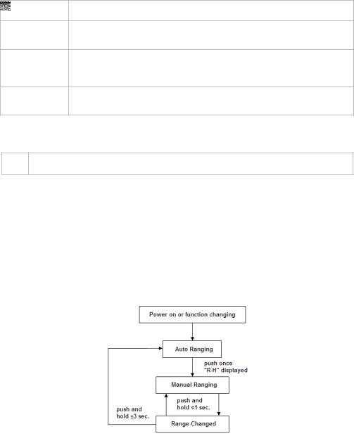
b.Range Control Button
Range for AC/DC voltage, AC/DC current(IA and mA only), Resistance and Frequency measuring can be selected manually or autorange. Push this button as following to choose range the desired mode or range.
25.02.2011 |
6 |
©Velleman nv |
DVM68 |
Rev. 01 |
c.DATA HOLD button
When this button is pushed, the display will show the last reading and " D-H " symbol will appear until the button is pushed again.
Data holding will be cancelled automatically when the function switch is rotated.
d.AC/DC Current of  /
/  selecting button
Push this button to select AC or DC current measuring function when the function switch is set
at IA, mA, A positions.
Push this button to select  or
or  measuring when the function swi tch is set at
  /
/  position.
e.Input jacks
This meter has four input jacks that are protected against overload to the limits. During use, connect the black test lead to the COM jack and the red test lead as shown below
Function |
Red Lead Connection |
Input Limits |
|
DCV / ACV |
V / Ω / F |
1000V DC or 750V AC rms |
|
|
kHz |
V / Ω / F |
250V DC o r AC rms |
Ω / |
/ |
V / Ω / F |
250V DC o r AC rms |
|
|
||
IA / mA |
mA / Cx |
300mA DC or AC rms |
|
|
nF / IF |
mA / Cx |
300mA fuse protected |
|
A |
A |
10A DC or AC rms |
IA/ mA and A range s are protected by fuses.
7. Operation
 Risk of electric shock during operation. Be very careful when measuring live circuits.
Before measuring, always make sure the meter and/or test probes are not damaged and verify the connections, selected function and range.
∙Never exceed the limit value for protection. This limit value is listed separately in the specifications for each range of measurement.
∙Do not touch unused terminals when the meter is linked to a circuit wh ich is being tested.
∙Only use the meter in the indicated overvoltage/installation category. Never measure voltages that might exceed the indicated category values.
∙Disconnect the test leads from the tested circuit before rotating the ra nge selector in order to change functions.
∙When carrying out measurements on a TV set or switching power circuits, always remember that high amplitude voltage pulses at the test points might damage th e meter.
∙Always be careful when working with voltages above 60Vdc or 30Vac rms. Keep your fingers behind the probe barriers at all times during measurement.
∙Do not measure current in circuits with voltages > 250V
∙Never perform resistance, diode, continuity or capacitance measurements on live circuits. Make sure all capacitors in the circuit are discharged.
7.1 Voltage measurements
Do not measure circuits where voltages > 600V CAT III or > 1000V CAT II may occur.
Always be careful when working with voltages above 60Vdc or 30 Vac rms. Keep your fingers behind the probe barriers at all times during measurement. Do not touch unused terminals when the meter is linked to a circuit which is being teste d.
∙Connect the black test lead to the COM jack and the red test lead to the VLF jack.
∙ Set the rotary selector to V for AC measurements or to V
 for DC measurements.
∙Connect the test leads to the circuit under test.
∙The measured value appears on the display.
∙When desired, select a range manually with the RANGE button.
25.02.2011 |
7 |
©Velleman nv |
DVM68 |
Rev. 01 |
Notes:
∙For DC-measurements: when a negative polarity is present at the r ed test lead, the indicated value is preceded by a “-” sign.
∙When the measured value is higher than the selected range limit, the display will show “OL”. Select a higher range.
7.2Current measurements
 Do not measure current in circuits with voltages > 250V
Current measurements: IAmA jack max. 300mA; for measurements up to 10A use the 10A jack. When measuring currents above 5A, max. 15s continuous measurement followed by a 10 minutes break between 2 measurements.
Always be careful when working with voltages above 60Vdc or 30Vac rms. Keep your fingers behind the probe barriers at all times during measurement.
∙For measurements up to 300mA: connect the red test lead to the "IAmA" jack and the black lead to the "COM" jack.
∙For measurements up to 10A: connect the red test lead to the "10A " jack and the black lead to the "COM" jack.
∙Set the function selector to A
∙Set the function selector to mA
for measurements up to 10A on the 10A jack.
 or IA
or IA  for measurements up to 3 00mA on the IAmA jack.
∙When the range is unknown, always select the highest possible range and lower to the appropriate range.
∙Connect the test probes in series with the circuit.
∙Read the measured value from the display.
∙When desired, select a range manually with the RANGE button.
Notes:
∙For DC-current measurements, when a negative polarity is present at the red test lead, the indicated value is preceded by a “-” sign.
∙The IAmA-range is protected against over-current with a F300mA 250V fuse (Ø5x20mm), the 10A-range is protected against over-current with a F10A 250V fuse (Ø6.3x30mm).
∙When measuring above 5A, max. 15s continuous measurement followed by a 10 minutes break between 2 measurements.
∙When the measured value is higher than the selected range limit, the display will show “OL”. Select a higher range.
7.3Resistance measurements
Do not perform resistance measurements on live circuits.
Make sure all capacitors in the circuit are discharged.
∙Connect the red test lead to the "VJF" jack and the black lead to the "COM" jack.
∙Set the rotary switch to the Ω range.
∙Connect the test probes to the circuit/component under test.
∙The measured value appears on the display.
∙When desired, select a range manually with the RANGE button.
Notes:
oNever perform resistance measurements on a live circuit and make sure all capacitors are completely discharged.
oFor resistance measurements above 3.26ML the meter needs a few seconds to stabilize the read-out.
oShould the measured resistance exceed the selected range or in case of an open circuit, the display will show “OL”.
7.4 Continuity & diode test
Do not perform continuity or diode measurements on live ci rcuits. Make sure all capacitors in the circuit are discharged.
∙Connect the black test lead to the COM jack and the red test lead to th e VJF jack.
∙Set the rotary selector to  /
/  .
.
25.02.2011 |
8 |
©Velleman nv |

DVM68 |
Rev. 01 |
Continuity test
∙Press the  /
/  .button until the
  symbol appears on the display.
∙Connect the test leads to the circuit under test.
∙When the measured resistance is less than 50Ω a continuous beep is produced and the
resistance value is showed on the display. Should the measured resist ance exceed the selected range or in case of an open circuit, the display will show “OL”.
Diode test
∙Press the  /
/  .button until the
  symbol appears on the display.
∙Connect the red test lead to the anode; connect the black test lead to the cathode of the diode. The meter will display the approximate forward voltage drop. If the lead connection is reversed, the meter will display “OL”.
Notes:
∙Never perform continuity or diode measurements on a live circuit and make sure all capacitors are completely discharged.
∙Measuring diodes that are part of a circuit might produce faulty results. Consider disconnecting them from the circuit.
7.5Capacitance measurements
Do not perform capacitance measurements on live circuits.
∙Connect the red test lead to the "mA Cx" jack and the black lead to the "COM" jack.
∙Set the rotary switch to nF or IF.
∙Connect the test probes to the capacitor. Mind the polarity when measuring polarized capacitors.
∙The capacitance value is shown on the display.
Notes:
o It takes a few seconds before the meter stabilizes. This is normal behavior.
oThe range control mode in capacitance measurement is manual ran ging and only two ranges (326nF, 32.6IF) are provided.
oIf Range Control Button is used in this measuring function, decimal points may be at incorrect positions.
oAt the nF range, when the capacitor to be measured is not connected to test leads, the LCD may not read zero, but a few counts. These counts have to be substracted from measuring results.
o When the capacity is higher than the measuring range, the display shows ‘OL’.
oNever perform capacitance measurements on a live circuit and ma ke sure all capacitors are completely depleted.
7.6Frequency measurements
Do not perform frequency measurements in circuits with voltages > 600V CAT III of 1000V CAT II
Always be careful when working with voltages above 60Vdc or 30Vac rms. Keep your fingers behind the probe barriers at all times during measurement Do not touch unused terminals when the meter is linked to a circuit which is being tested.
∙Connect the red test lead to the "VJF" jack and the black lead to the "COM" jack.
∙Set the rotary switch to Hz.
∙Connect the test probes to the circuit.
∙The frequency is shown on the display.
Notes:
oThe input voltage should be between 200mV and 10V rms AC. If the voltage is more than 10V rms, reading may be out of the accuracy range.
o When the frequency is higher than the measuring range, the display shows ‘OL’. o Use a shielded cable for measuring small signals in a noisy environment.
25.02.2011 |
9 |
©Velleman nv |

DVM68 |
Rev. 01 |
7.6 Transistor Test
Do not perform transistor measurements on live circuits.
∙Set the function switch at hFE position.
∙Identify whether the transistor is NPN or PNP type and locate emitter, base and collector lead.
∙Insert leads of the transistor to be tested into proper holes of the testi ng socket on the front panel.
∙LCD display will show the approximate hFE value at the test condition of base current 10 IA and Vce 3.2V.
8. Cleaning and maintenance
Do not replace internal parts yourself. Replace damaged or lost accessories by identical ones with the same specifications. Order spare accessories e.g. test probes at your dealer.
 Switch off the meter and remove test leads prior to replacing the battery or fuses.
WARNING: To avoid electrical shock always disconnect the test l eads prior to opening the housing.
Remark: refer to the warning on the back of the meter
a. General mainenance:
∙Wipe the device regularly with a moist, lint-free cloth. Do not use alco hol or solvents. b. Fuse Replacement
∙Remove test probes from the circuit under test. Remove the test probe s from the input jacks.
∙Switch off the multi-meter.
∙Remove the 3 screws at the back and gently open the meter.
∙Remove the fuse from the fuse holder and replace it with a new fuse of the same type and with the same specifications (F300mA/250V, Ø5x20mm – F10A/250V, Ø6.3x30mm).
∙Close the meter carefully.
c. Battery Replacement
∙Remove the battery as soon as the “  ” indication appears on the display.
∙Remove test probes from the circuit under test. Remove all test leads from the input jacks.
∙Switch off the multi-meter.
∙Remove the 3 screws at the back and gently open the meter.
∙Replace the battery by a new battery of the same type and with the same specifications (6LR61/6F22 9V alkaline, do not use rechargeable batteries)
∙Close the meter carefully
Notes:
o Never open the housing when test leads are connected to the input jacks. o Do not try to repair or calibrate the meter yourself; contact your d ealer.
o Replace damaged accessories immediately; order them at your local dealer.
oDo not use the meter when it is damaged.
9.Technical specifications
This device is not calibrated when purchased!
Regulations concerning environment of use:
∙Use this meter only for measurements in CAT I, CAT II and CAT III en vironments (see §4)
∙Use this meter only in a pollution degree 2 environment (see §5)
Max. voltage between terminal and earth |
1000V DC or 750V AC rms (sinus) |
Display |
3 ¾ digit LCD, 3260 counts max, |
|
2-3 readings / sec |
Fuse protection |
IA & mA range : F 300mA/250V |
|
A range : F 10A/250V |
Power Supply |
9V battery |
Ranging method |
Auto / Manual |
Polarity indication |
" - " displayed |
25.02.2011 |
10 |
©Velleman nv |
|
DVM68 |
|
Rev. 01 |
|
Overrange indication |
" OL " displayed auto matically |
|
|
Low Battery indication |
" " displayed |
|
|
|
|
|
|
Operating temperature |
0°C to 40°C |
|
|
Storage temperature |
-10°C to 50°C |
|
|
Dimensions |
91 x 189 x 31.5 mm |
|
|
Weight |
310 g (incl. battery) |
|
9.1 DC Voltage
Range |
Resolution |
Accuracy |
|
326mV |
0.1mV |
± 0.5% of rdg ± 2 digits |
|
3.26V |
1mV |
||
|
|||
32.6V |
10mV |
± 0.3% of rdg ± 2 digits |
|
326V |
0.1V |
||
|
|||
1000V |
1V |
± 0.5% of rdg ± 2 digits |
|
Input impedance : 10MΩ, more than 100MΩ at 326mV range |
|||
9.2 AC Voltage
|
Range |
Resolution |
Accuracy |
|
3.26V |
1mV |
|
|
32.6V |
10mV |
± 0.8% of rdg ± 3 digits |
|
326V |
0.1V |
|
|
|
||
|
750V |
1V |
|
|
Input impedance : 10MΩ |
|
|
|
Frequency range : 40 to 1000Hz, 40 to 200Hz at 3.26V range |
||
9.3 DC Current |
|
|
|
|
Range |
|
Resolution |
Accuracy |
Burden Voltage |
|
326IA |
|
0.1IA |
|
0.5mV / IA |
|
3260IA |
|
1IA |
± 1.2% of rdg ± 3 digits |
0.5mV / IA |
|
32.6mA |
|
10IA |
8.0mV / mA |
|
|
|
|
|||
|
326mA |
|
0.1mA |
|
8.0mV / mA |
|
10A |
|
10mA |
± 2.0% of rdg ± 5 digits |
0.02V / A |
|
Overload protection : F 300mA fuse for IA and mA ranges, F 10A fuse for A range |
||||
9.4 AC Current |
|
|
|
||
|
Range |
|
Resolution |
|
Accuracy |
Burden Voltage |
|
326IA |
|
0.1IA |
|
|
0.5mV / IA |
|
3260IA |
|
1IA |
|
± 1.5% of rdg ± 5 digits |
0.5mV / IA |
|
32.6mA |
|
10IA |
|
8.0mV / mA |
|
|
|
|
|
|||
|
326mA |
|
0.1mA |
|
|
8.0mV / mA |
|
10A |
|
10mA |
|
± 3.0% of rdg ± 7 digits |
0.02V / A |
|
Overload protection : F 300mA fuse for IA and mA ranges, F 10A fuse for A range |
|||||
|
Frequency range : 40Hz to 1000Hz |
|
|
|||
9.5 Resistance |
|
|
|
|
||
Range |
Resolution |
Accuracy |
|
326Ω |
0.1Ω |
± 0.8% of rdg ± 3 digits |
|
3.26kΩ |
1Ω |
||
|
|||
32.6kΩ |
10Ω |
|
|
326kΩ |
100Ω |
± 0.8% of rdg ± 3 digits |
|
3.26MΩ |
1kΩ |
|
|
32.6MΩ |
10kΩ |
± 1.2% of rdg ± 2 digits |
Maximum Open Circuit Voltage : 1.3V
25.02.2011 |
11 |
©Velleman nv |

|
|
|
DVM68 |
|
Rev. 01 |
||
9.6 Capacity |
|
|
|
|
|
|
|
|
|
|
|
|
|
|
|
|
Range |
|
Resolution |
|
|
Accuracy |
|
|
326nF |
|
0.1nF |
|
|
± 3.0% of rdg ± 5 digits |
|
|
32.6IF |
|
10nF |
|
|
|
|
|
|
|
|
|
|
||
9.7 Frequency |
|
|
|
|
|
|
|
|
|
|
|
|
|
|
|
|
Range |
|
Resolution |
|
Accuracy |
|
|
|
32.6kHz |
|
10Hz |
|
± 1.2% of rdg ± 3 digits |
|
|
|
150kHz |
|
100Hz |
|
± 2.5% of rdg ± 3 digits |
|
|
Sensivity : 200mV rms up to 50kHz, 1V rms for 50kHz to 150kHz
10.Accessories
∙Test leads
∙Battery (9V)
∙Operation Manual
∙Holster
How to use the holster
The holster is used to protect the meter and to make the measure ment more confortable. Refer to the illustrations on page 2 of this manual:
∙Support the meter with a standard angle. (fig. a)
∙Support the meter with a small angle using the little stand.(fig. b)
∙Hang the meter on the wall using the little stand. (fig. c)
∙Take the little stand off from the back side of the large stand and insert it into holes located upper on the holster.
∙Hold test leads. (fig. d)
Use this device with original accessories only. Velleman nv cannot be held responsible in the event of damage or injury resulted from (incorrect) use of th is device. For more info concerning this product and the latest version of this user ma nual, please visit our website www.velleman.eu. The information in this manual is subject to change without prior notice.
© COPYRIGHT NOTICE
The copyright to this manual is owned by Velleman nv. All worldwide rights rese rved. No part of this manual or may be copied, reproduced, translated or reduced to any electronic mediu m or otherwise without the prior written consent of the copyright holder.
GEBRUIKERSHANDLEIDIN G
1. Inleiding
Aan alle ingezetenen van de Europese Unie Belangrijke milieu-informatie betreffende dit product
Dit symbool op het toestel of de verpakking geeft aan dat, als het na zijn levenscyclus wordt weggeworpen, dit toestel schade kan toebrengen aan het milieu. Gooi dit toestel (en eventuele batterijen) niet bij het gewone huishoudelijke afval; het moet bij een gespecialiseerd bedrijf terechtkomen voor recyclage. U moet dit toestel naar uw verdeler of naar een lokaal recyclagepunt brengen. Respecteer de plaatselijke milieuwetgeving.
Hebt u vragen, contacteer dan de plaatselijke autoriteiten inzake verwijdering.
Dank u voor uw aankoop! Lees deze handleiding grondig voor u het toestel in gebruik neemt. Werd het toestel beschadigd tijdens het transport, installeer het dan niet en raadpleeg uw dealer.
Uw DVM 68 is een professionele digitale multimeter met een 3 ¾ digit LCD uitlezing en een automatische meetbereikinstelling. U kunt dit toestel gebruiken voor een b reed scala toepassingen zoals thuis, op de werf, op school, … De toegepaste technologie waarborgt een betrouwbare, nauwkeurige en langdurige werking op hoog niveau.
25.02.2011 |
12 |
©Velleman nv |

|
DVM68 |
Rev. 01 |
U kunt er volgende zaken mee meten : |
|
|
Gelijkspanning |
Wisselspanning |
|
Gelijkstroom |
Wisselstroom |
|
Weerstand |
Capaciteit |
|
Frequentie |
Continuïteit |
|
Daarenboven kunnen diodes en transistoren (versterkingsfactor hFE) getest worden.
Wees uiterst voorzichtig tijdens het gebruik van dit toestel. Verkeerd of onoordeelkundig gebruik kan tot ernstige gevolgen leiden. Leef alle veiligheidsvoorschriften nauwkeurig na. Gebruik dit toestel niet indien U over onvoldoende kennis beschikt betreffende elektrische schakelingen en meettechniek.
Dit toestel is niet geschikt voor commercieel of industrieel gebruik.
Raadpleeg de Velleman® serviceen kwaliteitsgarantie achteraan deze handleiding.
2. Gebruikte symbolen
Dit symbool staat voor instructies lezen:
Het niet lezen van deze instructies en de handleiding kan leiden tot beschadiging, letsel of de dood
Dit symbool betekent gevaar:
Gevaarlijke toestand of actie die kan leiden tot letsel of de dood
Dit symbool betekent risico op gevaar/schade:
Risico op het ontstaan van een gevaarlijke toestand of actie die kan leiden tot schade, letsel of de dood
Dit symbool betekent aandacht, belangrijke informatie:
Het niet in acht nemen van deze informatie kan leiden tot een g evaarlijke toestand
AC (wisselstroom)
DC (gelijkstroom)
zowel wisselals gelijkstroom
Dubbele isolatie (klasse II-bescherming)
Aarding
 Zekering
Capaciteit (condensator)
Diode
Continuiteit
3. Veiligheidsinstructies
Lees deze handleiding grondig, leer eerst de functies van het toestel kennen voor u het gaat gebruiken.
Gebruik het toestel enkel waarvoor het gemaakt is. Bij onoordeelkundig gebruik vervalt de garantie. De garantie geldt niet voor schade door het negeren van bepaalde richtlijnen in deze handleiding en uw dealer zal d e verantwoordelijkheid afwijzen voor defecten of problemen die hier rechtstreeks v erband mee houden.
Volg de richtlijnen hieronder om een veilig gebruik te garan deren en alle functies van de meter ten volle te benutten.
Respecteer tijdens het gebruik van de meter alle richtlijnen aangaande beveiliging tegen elektroshocks en verkeerd gebruik. De aangegeven limietwaarden mogen nooit overschreden worden
WAARSCHUWING:
Om elektrische schokken te vermijden, verwijder de testsnoeren alvorens de behuizing te openen
Opmerking: dit is de vertaling van de waarschuwing die zich onderaan op de
25.02.2011 |
13 |
©Velleman nv |
DVM68 |
Rev. 01 |
achterkant van het toestel bevindt.
WAARSCHUWING:
Om brand te vermijden, gebruik identieke zekeringen.
Opmerking: dit is de vertaling van de waarschuwing die zich op de achterkant van het toestel bevindt.
Houd dit toestel uit de buurt van kinderen en onbevoegden.
Bescherm het toestel tegen schokken. Vermijd brute kracht tijdens de bediening.
Vermijd koude, hitte en grote temperatuursschommelingen, Als het toestel van een koude naar een warme omgeving verplaatst wordt, laat het toestel dan eerst voldoende op temperatuur komen. Dit om meetfouten en condensvorming te vermijden.
Dit is een installatiecategorie CAT III 600 V/CAT II 1000 V meetinstrument.
Gebruik dit toestel nooit in een hogere CAT dan aangegeven. Zie §4
Overspanning-/installatiecategorie.
Vervuilingsgraad 2-toestel, enkel geschikt voor gebruik binnenshuis! Stel dit


 toestel niet bloot aan stof, regen, vochtigheid en opspattende vloeistoffen. Niet

 geschikt voor industrieel gebruik. Zie §5 Vervuilingsgraad/Vervuilingsgraad.
Controleer voor gebruik indien de meetsnoeren in goede staat verkeren. Houd tijdens metingen uw vingers achter de beschermingsrand van de
meetpennen! Raak geen vrije meetbussen aan wanneer de meter met een circuit is verbonden.
Let erop dat de meter zich in de juiste stand bevindt alvorens deze te verbinden met het testcircuit.
Elektrocutiegevaar tijdens het gebruik van deze multimeter. Wees voorzichtig tijdens het meten van een circuit onder spanning. Wees uiterst voorzichtig bij metingen > 60 VDC of 30 V RMS AC.
Meet niet aan circuits waarin spanningen kunnen voorkome n > 1000 V.
Meet geen stroom in circuits met een spanning > 250 V.
Voer geen weerstand-, diodeof continuïteitsmetingen uit in circuits waarop spanning aanwezig is, of zou kunnen voorkomen.
Bij stroommetingen > 5 A max. 15 sec. aaneensluitend meten, telkens 10 min. wachten tussen 2 metingen.
Wees voorzichtig bij metingen aan toestellen zoals tv's of schakelende voedingen, Let op bij metingen op circuits zoals TV’s of schakelende vo edingen, er kunnen spanningspieken voorkomen die de meter kunnen beschadigen
De gebruiker mag geen inwendige onderdelen vervangen. Vervang beschadigde of verloren accessoires enkel door accessoires van hetzelfde type of met dezelfde specificaties. Bestel reserveaccessoires zoals meetsnoeren bij uw dealer.
Schakel de meter uit en verwijder de testsnoeren vóór u de batterij of zekering vervangt.
Om veiligheidsredenen mag u geen wijzigingen aanbrengen . Schade door wijzigingen die de gebruiker heeft aangebracht valt niet onder de garantie.
4. Overspanning-/installatiecategorie
DMM’s worden opgedeeld volgens het risico op en de ernst van spanningpieken die kunnen optreden op het meetpunt. Spanningspieken zijn kortstondige uitbarstingen van energie die geïnduceerd worden in een systeem door bvb. blikseminslag op een hoogspanningslijn.
De bestaande categorieën volgens EN 61010-1 zijn:
25.02.2011 |
14 |
©Velleman nv |

DVM68 |
Rev. 01 |
CAT I Een CAT I meter is geschikt voor metingen op beschermde elektronische circuits die niet rechtstreeks verbonden zijn met het lichtnet, bvb. Elektronische schakelingen, stuursignalen…
CAT II Een CAT II meter is geschikt voor metingen in CAT I omgevingen en op enkelfasige apparaten die aan het lichtnet gekoppeld zijn door middel van een stekker en circuits in een normale huiselijke omgeving, op voorwaarde dat het circuit minstens 10m verwijderd is van een CAT III omgeving, en minstens 20m van een CAT IV omgeving. Bvb. Huishoudapparaten, draagbare gereedschappen ...
CAT III Een CAT III-meter is geschikt voor metingen in CAT I- en CAT II -omgevingen, alsook voor metingen aan enkelen meerfasige (vaste) toestellen op meer dan 10 m van een CAT IV-omgeving, en metingen inof aan distributiekasten (zekeringkasten, verlichtingscircuits, elektrisch fornuis).
CAT IV Een CAT IV meter is geschikt voor metingen in CAT I, CAT II en CAT III omgevingen alsook metingen op het primaire toevoerniveau.
Merk op dat voor metingen op kringen waarvan de toevoerkabels buitenshuis lopen (zowel bovenals ondergronds) een CAT IV meter moet gebruikt worden.
Waarschuwing:
Dit toestel is ontworpen conform EN 61010-1 installatiecategorie CAT III 600V / CAT II 1000V. Dit houdt bepaalde gebruiksbeperkingen in die te maken hebben met voltages en spanningspieken die kunnen voorkomen in de gebruiksomgeving, zie tabel hierboven.
Dit toestel is geschikt voor metingen tot max. 1000 V aan:
-Beschermde circuits die beveiligd of niet rechtstreeks verbonden zijn aan het lichtnet zoals bvb. stuursignalen en metingen aan elektronica, circuits achter een sc heidingstransformator
-Circuits rechtstreeks verbonden aan het lichtnet maar beperkt tot:
Metingen aan monofaseapparaten verbonden met het lichtnet door mi ddel van een stekker (stopcontact)
Metingen aan monofaseapparaten en circuits rechtstreeks verbonden met het lichtnet in een gewone huiselijke omgeving op meer dan 10m van een CAT III omgeving en 20 m van een CAT IV omgeving. (bv. verlichtingskringen op meer dan 10m van de ze keringkast)
Dit toestel is geschikt voor metingen tot max. 600 V aan:
-Metingen in-/aan laagspanningsborden (zekeringkast na de tellerkast)
-Metingen aan monoen meerfaseapparaten en circuits uitgezonderd in een CAT IV omgeving
(bvb. metingen aan stopcontacten, elektrisch fornuis, verlichtingskringen, busbars, zekeringen en automaten)
DIT TOESTEL IS NIET GESCHIKT VOOR METINGEN VAN/AAN:
-Spanningen hoger dan 1000 V.
-Metingen aan distributieborden en buiteninstallaties. (hieronder vallen de tellerkast en toestellen/circuits buiten of los van de huiselijke omgeving zoals kringe n in schuurtjes, tuinhuisjes en losstaande garagesof kringen verbonden via ondergro ndse leidingen zoals tuinverlichting of vijverpompen.
Dit toestel is enkel geschikt voor metingen tot max. 600V in een CAT III omgeving en tot max. 1000V in een CAT II omgeving.
5. Vervuilingsgraad (pollution degree)
IEC 61010-1 specifieert verschillende types vervuilingsgraden welke bepaa lde risico’s met zich meebrengen. Iedere vervuilingsgraad vereist specifieke beschermingsmaatregelen. Omgevingen met een hogere vervuilingsgraad hebben een betere bescherming nodig tegen mogelijke invloeden van de verschillende types vervuiling die in deze omgeving kunn en voorkomen. Deze bescherming bestaat hoofdzakelijk uit aagepaste isolatie en een aangepaste behuizing. De opgegeven Pollution degree waarde geeft aan in welke omgeving dit apparaat veilig gebruikt kan worden.
Pollution |
Omgeving zonder, of met enkel drogeniet geleidende vervuiling. De voorkomende |
degree 1 |
vervuiling heeft geen invloed (Komt enkel voor in uitzondelij ke omgevingen) |
Pollution |
Omgeving met enkel niet geleidende vervuiling, Uitzonderlijk kan condensatie |
degree 2 |
voorkomen. (bvb. huishoudelijkeen kantooromgeving) |
25.02.2011 |
15 |
©Velleman nv |

DVM68 |
Rev. 01 |
Pollution |
Omgeving waar geleidende vervuiling voorkomt, of droge niet geleidende vervuiling |
degree 3 |
die geleidend kan worden door condensatie. (industriële omgevingen en omgevingen |
|
die blootgesteld worden aan buitenlucht zonder rechtstreeks contact met neerslag |
Pollution |
Omgeving waar frequent geleidende vervuiling voorkomt, bvb. veroorzaakt door |
degree 4 |
geleidend stof, regen of sneeuw (in openlucht en omgevingen met een hoge |
|
vochtigheidsgraad of hoge concentraties fijn stof) |
Waarschuwing:
Dit toestel is ontworpen conform EN 61010-1 vervuilingsgraad Pollution degree 2. Dit houdt bepaalde gebruiksbeperkingen in die te maken hebben met de pollutie die kan voorkomen in de gebruiksomgeving, zie tabel hierboven.
Dit toestel is enkel geschikt voor gebruik in omgevingen met Pollution degree 2 classificatie
6. Omschrijving
Raadpleeg de figuren op pagina 2 van deze handleiding.
a. Multimeter
1 |
Lcd-scherm |
|
6 |
Functieen aan/uitschakelaar |
2 |
Meetbereik instelling |
|
7 |
V/Ω/F ingangsbus |
3 |
Vasthouden meetwaarde |
|
8 |
COM ingangsbus |
4 |
Wisselstroom/gelijkstroom of |
/ |
9 |
mA/Cx ingangsbus |
|
keuzeschakelaar |
|
|
|
5 |
Transistortestvoetje |
|
10 |
10A ingangsb us |
b.Keuzeknop "RANGE" (Meetbereik)
Meetbereik instelling voor gelijken wisselspanning, gelijken wisselstroom (enkel IA en mA bereik), weerstand en frequentiemeting. Bij de voorgaande meetfuncties kan het meetbereik zowel automatisch als manueel ingesteld worden. Druk op de knop volgens onderstaand schema om de meetbereikmode en het gewenste meetbereik in te schakelen.
c."DATA HOLD" - knop
Druk op deze knop om het meetresultaat te bewaren. Op het scherm blijft de meting staan en wordt het " D-H " -symbool getoond, tot de knop nogmaals ingedrukt wordt. De bewaarfunctie wordt automatisch uitgeschakeld wanneer de draaischakelaar wordt be diend.
25.02.2011 |
16 |
©Velleman nv |
DVM68 |
Rev. 01 |
d.AC/DC of  /
/  selektieknop
Bij stroommetingen (IA, mA of A positie) wordt deze knop AC (wisselstroom) of DC (gelijkstroom) ingesteld. Wanneer de draaischakelaar in stand  /
/  staat, wordt geselekteerd tussen continuïteitsmeting (
  ) en diodetest (
  ).
).
e.Aansluitingsbussen
Dit toestel bezit vier aansluitingen voor meetsnoeren. Het zwarte meetsnoer wordt altijd met de "COM" (gemeenschappelijke) aansluiting verbonden, terwijl het rode meetsnoer naargelang de meting verbonden wordt volgens onderstaand schema.
Functie |
Rood meetsnoer aansluiting |
Max. w aarden |
|
DCV / ACV |
V / Ω / F |
1000V DC of 750V AC rms |
|
|
kHz |
V / Ω / F |
250V DC of AC rms |
Ω / |
/ |
V / Ω / F |
250V DC of AC rms |
|
|
||
IA / mA |
mA / Cx |
300mA DC of AC rms |
|
nF / IF |
mA / Cx |
300mA beveilig d door zekering |
|
|
A |
A |
10A DC of AC rms |
De IA/ mA en A-bereiken worden be veiligd door zekeringen.
7. Gebruik
Elektrocutiegevaar tijdens het gebruik van deze multimeter.
Wees voorzichtig tijdens het meten van een circuit onder spanning.
Controleer vooraleer te meten altijd indien de aansluitingen, de fun ctie en het bereik correct zijn ingesteld en indien het toestel en/of de testsnoeren niet beschadigd zijn
∙Overschrijd nooit de grenswaarden! Deze waarden worden vermeld in de specificaties van elk meetbereik.
∙Raak geen ongebruikte ingangsbussen aan wanneer de meter gekoppeld is aan een schakeling die u aan het testen bent.
∙Gebruik de meter enkel voor het meten in de aangeduide meetcategorie-installaties en meet geen voltages die de aangeduide waarden kunnen overschrijden.
∙Koppel de testsnoeren los van het meetcircuit vooraleer u een andere functie kiest met de draaischakelaar.
∙Let op bij metingen op circuits zoals tv’s of schakelende voedingen, er kunnen spanningspieken voorkomen die de meter kunnen beschadigen.
∙Wees uiterst voorzichtig wanneer u werkt met voltages boven 60VDC o f 30VAC RMS. Houd tijdens metingen uw vingers te allen tijde achter de beschermingsrand van de meetpennen!
∙Meet geen stroom in circuits met een spanning > 250V
∙Voer nooit weerstandsmetingen, continuïteitstest, transistortest of diod etest of capaciteitsmetingen uit op schakelingen die onder spanning staan. Vergewis uzelf ervan dat condensatoren die zich in het circuit bevinden ontladen zijn.
7.1 Spanningsmetingen
Meet niet aan circuits waarin spanningen kunnen voorkomen > 60 0V CAT III of 1000V CAT II
Wees uiterst voorzichtig wanneer u werkt met voltages boven 60V dc of 30Vac rms. Hou tijdens metingen uw vingers te allen tijde achter de beschermingsrand van de meetpennen! Raak geen aansluitbussen aan tijdens de meting
∙Koppel het zwarte meetsnoer met de COM- en het rode meetsnoer met de VJF -bus.
∙Plaats de draaischakelaar op V voor wisselspanningsmeting of op V
  voor gelijkspanningsmeting.
∙Verbind de meetsnoeren met het te meten circuit.
∙De gemeten spanning kan afgelezen worden op de display.
∙Selecteer manueel bereik met de RANGE toets indien gewenst.
25.02.2011 |
17 |
©Velleman nv |
 Loading...