


19486-6NL-04
PNOZ X5, PNOZ X5J, PNOZ X5.1
4 D |
Betriebsanleitung |
4 E |
Instrucciones de uso |
4 GB |
Operating instructions |
4 I |
Istruzioni per l`uso |
4 F |
Manuel d'utilisation |
4 NL |
Gebruiksaanwijzing |
Sicherheitsbestimmungen |
Safety Regulations |
• Das Gerät darf nur von Personen installiert |
• The unit may only be installed and |
und in Betrieb genommen werden, die mit |
operated by personnel who are familiar |
dieser Betriebsanleitung und den gel- |
with both these instructions and the current |
tenden Vorschriften über Arbeitssicherheit |
regulations for safety at work and accident |
und Unfallverhütung vertraut sind. |
prevention. Follow VDE and local |
Beachten Sie die VDEsowie die örtlichen |
regulations especially as regards |
Vorschriften, insbesondere hinsichtlich |
preventative measures. |
Schutzmaßnahmen. |
• Transport, storage and operating conditions |
• Beim Transport, der Lagerung und im |
should all conform to EN 60068-2-6. |
Betrieb die Bedingungen nach EN 60068- |
• Any guarantee is void following opening of |
2-6 einhalten (s. technische Daten). |
the housing or unauthorised modifications. |
• Durch Öffnen des Gehäuses oder eigen- |
• The unit should be panel mounted, |
mächtige Umbauten erlischt jegliche Ge- |
otherwise dampness or dust could lead to |
währleistung. |
function impairment. |
• Montieren Sie das Gerät in einen Schalt- |
• Adequate protection must be provided on |
schrank; Staub und Feuchtigkeit können |
all output contacts especially with |
sonst zu Beeinträchtigungen der Funktio- |
capacitive and inductive loads. |
nen führen. |
|
• Sorgen Sie an allen Ausgangskontakten |
|
bei kapazitiven und induktiven Lasten für |
|
eine ausreichende Schutzbeschaltung. |
|
 Conseils préliminaires
•La mise en oeuvre de l’appareil doit être effectuée par une personne spécialisée en installations électriques, en tenant compte des prescriptions des différentes normes applicables (NF, EN, VDE...) notamment au niveau des risques encourus en cas de défaillance de l’équipement électrique.
•Respecter les exigences de la norme
EN 60068-2-6 lors du transport, du stockage et de l'utilisation de l'appareil.
•L’ouverture de l’appareil ou sa modification annule automatiquement la garantie.
•L’appareil doit être monté dans une armoire; l’humidité et la poussière pouvant entraîner des aléas de fonctionnement.
•Vérifiez que le pouvoir de coupure des contacts de sortie est suffisant en cas de circuits capacitifs ou inductifs.
Bestimmungsgemäße Verwendung
Das Sicherheitsschaltgerät dient dem sicherheitsgerichteten Unterbrechen eines Sicherheitsstromkreises. Das Sicherheitsschaltgerät erfüllt Forderungen der
EN 60947-5-1, EN 60204-1 und VDE 0113-1 und darf eingesetzt werden in Anwendungen mit
•Not-Halt-Tastern
•Schutztüren
•Lichtschranken
Intended Applications
The safety relay provides a safety-related interruption of a safety circuit. The safety relay meets the requirements of EN 60947-5-
1, EN 60204-1 and VDE 0113-1 and may be used in applications with
•E-STOP pushbuttons
•Safety gates
•Light barriers
Domaines d’utilisation
Le bloc logique de sécurité sert à interrompre en toute sécurité un circuit de sécurité. Le bloc logique de sécurité satisfait aux exigences des normes EN 60947-5-1,
EN 60204-1 et VDE 0113-1 et peut être utilisé dans des applications avec des
•poussoirs d'arrêt d'urgence
•protecteurs mobiles
•barrières immatérielles
Gerätebeschreibung
Das Sicherheitsschaltgerät ist in einem S-95- Gehäuse untergebracht. Es stehen verschiedene Varianten für den Betrieb mit Gleichspannung und eine Variante für den Betrieb mit Wechselspannung zur Verfügung.
Merkmale:
•Gerätetypen:
-PNOZ X5: Einoder zweikanalige Ansteuerung
-PNOZ X5.1: Einkanalige Ansteuerung mit interner Brücke zwischen S12-S22
ACHTUNG!
Die Betriebsart "manueller Start" ist unzulässig für das sicherheitsgerichtete Verhindern eines unerwarteten Anlaufs nach EN 1037
-PNOZ X5J: wie PNOZ X5, aber umgekehrte Polarität der Versorgungsspannung und geerdetes Pluspotenzial
•Relaisausgänge: 2 Sicherheitskontakte (Schließer), zwangsgeführt
•Anschlussmöglichkeit für Not-Halt-Taster, Schutztürgrenztaster und Starttaster
•Statusanzeige
•Überwachung externer Schütze möglich
•keine galvanische Trennung
Description
The Safety Relay is enclosed in a 22,5 mm S-95 housing. There are different versions available for AC operation and one for DC operation.
Features:
•Unit Types:
-PNOZ X5: Single or dual-channel operation
-PNOZ X5.1: Single-channel operation, link S12-S22
CAUTION!
„Manual“ reset is not permitted as a safety-related means of preventing unexpected (unintended) start up in accordance with EN 1037.
-PNOZ X5J: as the PNOZ X5, but the supply voltage polarity and the earthed + potential are reversed
•Relay outputs: 2 safety contacts (N/O), positive-guided.
•Connections for emergency stop button, safety gate limit switch and reset button.
•Status indicators
•Feedback control loop for monitoring external contactors/relays possible.
•No galvanic separation
Description de l’appareil
Inséré dans un boîtier S95, le bloc logique de sécurité est disponible en différentes versions pour les tensions d’alimentation alternatives et une version en alimentation continue (24 VDC).
Particularités :
•Types d’appareil:
-PNOZ X5: Commande par un ou deux canaux
-PNOZ X5.1: Commande en monocanal avec pont sur les bornes S12-S22
ATTENTION !
Le mode de fonctionnement
„Réarmement manuel“ n’est pas adapté pour éviter de façon sûre un démarrage intempestif d’après la norme EN 1037.
-PNOZ X5J: comme PNOZ X5, mais polarité inversée sur alimentation et mise à la masse du plus.
•Sorties disponibles : 2 contacts à fermeture de sécurité
•Bornes de raccordement pour poussoirs
AU, détecteurs de position et poussoir de validation
•LEDs de visualisation
•Auto-contrôle des contacteurs externes possible
•pas d'isolation galvanique
- 1 -
Das Schaltgerät erfüllt folgende Sicherheitsanforderungen:
•Schaltung ist redundant mit Selbstüberwachung aufgebaut
•Sicherheitseinrichtung bleibt auch bei Ausfall eines Bauteils wirksam.
•Bei jedem Ein-Aus-Zyklus der Maschine wird automatisch überprüft, ob die Relais der Sicherheitseinrichtung richtig öffnen und schließen.
The relay complies with the following safety requirements:
•The circuit is redundant with built-in selfmonitoring
•The safety function remains effective in the case of a component failure.
•The correct opening and closing of the safety function relays is tested automatically in each on-off cycle.
Le relais répond aux exigences suivantes :
•conception redondante avec autosurveillance
•sécurité garantie même en cas de défaillance d’un composant
•test cyclique (ouverture/fermeture des relais internes) à chaque cycle Marche/
Arrêt de la machine
Funktionsbeschreibung
Das Schaltgerät dient dem sicherheitsgerichteten Unterbrechen eines Sicherheitsstromkreises. Nach Anlegen der Versorgungsspannung leuchtet die LED
"POWER". Das Gerät ist betriebsbereit, wenn der Startkreis S33-S34 geschlossen ist.
•Eingangskreis geschlossen (z. B. Not-Halt- Taster nicht betätigt):
Relais K1 und K2 gehen in Wirkstellung und halten sich selbst. Die Statusanzeigen für
"CH.1" und "CH.2" leuchten. Die Sicherheitskontakte 13-14/23-24 sind geschlossen.
•Eingangskreis wird geöffnet (z. B. Not-Halt-
Taster betätigt):
Relais K1 und K2 fallen in die Ruhestellung zurück. Die Statusanzeige für "CH.1" und "CH.2" erlischt. Die Sicherheitskontakte 13- 14/23-24 werden redundant geöffnet.
Function Description
The relay provides a safety-oriented interruption of a safety circuit. When the operating voltage is supplied the LED "POWER" is illuminated. The unit is ready for operation, when the reset circuit S33-S34 is closed.
•Input circuit closed (e.g. the emergency stop button is not pressed):
Relays K1and K2 energise and retain themselves. The status indicators for "CH.1" and "CH.2" illuminate. The safety contacts (13-14/23-24) are closed.
•Input circuit is opened (e.g. emergency stop button is operated)
Relays K1 and K2 de-energise. The status indicators for "CH.1" and "CH.2" go out. The safety contacts (13-14/23-24) will be opened (redundant).
Description du fonctionnement
Le relais assure de façon sure, l’ouverture d’un circuit de sécurité. A la mise sous tension du relais (A1-A2), la LED "POWER" s'allume. Le relais est activé si le circuit de réarmement S33-S34 est fermé.
•Circuits d'entrée fermés (poussoir AU non actionné) :
Les relais K1 et K2 passent en position travail et s'auto-maintiennent. Les LEDs "CH.1" et CH.2" s'allument. Les contacts de sécurité (13-14/23-24) sont fermés.
•Circuits d'entrée ouverts (poussoir AU actionné) :
Les relais K1 et K2 retombent. Les LEDs "CH.1" et "CH.2" s'éteingnent. Les contacts de sécurité (13-14/23-24) s'ouvrent.
|
UB |
S11 S22 S33 S34 S12 S12 |
|
|
UB |
S11 S22 |
S33 S34 S12 |
S12 |
|
|
||
A1 (L+) |
A2 (L-) |
13 |
23 |
A1 (L-) A2 (L+) |
13 |
23 |
||||||
|
|
Start |
K1 |
|
|
|
|
Start |
K1 |
|
|
|
|
|
|
|
|
|
|
|
|
|
|
||
|
|
Unit |
|
|
|
|
|
Unit |
|
|
|
|
|
|
|
Start |
K2 |
|
|
|
|
|
Start |
K2 |
|
|
|
|
|
|
|
|
|
|
|
|
||
|
|
|
Unit |
|
|
|
|
|
|
Unit |
|
|
|
|
|
|
14 |
24 |
|
|
|
|
|
14 |
24 |
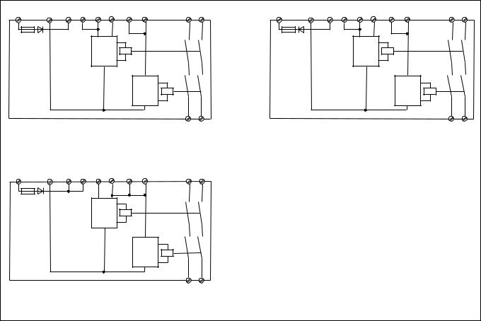
Fig. 1: PNOZ X5 Innenschaltbild/Internal Wiring Diagram/Schéma de principe
Fig. 2: PNOZ X5J Innenschaltbild/Internal Wiring Diagram/Schéma de principe
A1 (L+) UB A2 (L-) S11 S33 S34 S22 S12 S12 |
13 |
23 |
|
Start |
K1 |
|
|
|
|
|
|
Unit |
|
|
|
|
Start |
K2 |
|
|
|
|
|
|
Unit |
|
|
|
|
14 |
24 |
Fig. 3: PNOZ X5.1 Innenschaltbild/Internal Wiring
Diagram/Schéma de principe
Betriebsarten:
•Einkanaliger Betrieb: Eingangsbeschaltung nach VDE 0113 und EN 60204; keine
Redundanz im Eingangskreis; Erdschlüsse im Startkreis werden erkannt. Bei Erdschlüssen im Not-Halt-Kreis löst die
Sicherung der Versorgungsspannung aus.
•Zweikanaliger Betrieb: Redundanter Eingangskreis, Erdschlüsse im Tasterkreis werden erkannt.
•Automatischer Start: Gerät ist aktiv, sobald Eingangskreis geschlossen ist.
Operating Modes
•Single-channel operation: Input wiring according to VDE 0113 and EN 60204, no redundancy in the input circuit. Earth faults are detected in the reset circuit. Earth faults in the emergency stop circuit trigger the internal electronic fuse.
•Dual-channel operation: Redundancy in the input circuit. Earth faults in the emergency stop circuit are detected.
•Automatic reset: Unit is active as soon as the input circuit is closed.
-2 -
Modes de fonctionnement
•Commande par 1 canal : conforme aux prescriptions de la EN 60204, pas de redondance dans le circuit d’entrée. La mise à la terre du circuit de réarmement est détectée. En cas de mise à la terre des circuits d'entrée, le fusible électronique déclenche.
•Commande par 2 canaux: circuit d’entrée redondant, la mise à la terre est détectée.
•Réarmement automatique : le relais est activé dès la fermeture des canaux d’entrée.

•Manueller Start: Gerät ist erst dann aktiv, wenn ein Starttaster betätigt oder ein Startkontakt geschlossen wird. Dadurch ist ein automatischer Start des Schaltgeräts nach Spannungsausfall und -wiederkehr ausgeschlossen.
ACHTUNG!
Beim PNOZ X5.1 keine Sicherheitsfunktion.
•Kontaktvervielfachung und -verstärkung durch Anschluss von externen Schützen
•Manual reset: Unit is only active when a reset button has been pressed or reset contact is closed. Therefore, automatic reset is prevented following a loss/return of supply voltage.
CAUTION!
There is no safety function on the PNOZ X5.1
•Increase in the number of contacts available contacts by connecting external contactors / relays.
•Réarmement manuel : le relais n’est activé qu’après une impulsion sur un poussoir de validation. Un réarmement automatique du relais après une coupure d’alimentation est ainsi impossible.
ATTENTION !
PNOZ X5.1 : fonction non sécuritaire !
•Augmentation du nombre de contacts ou du pouvoir de coupure par l’utilisation de contacteurs externes.
Montage
Das Gerät muss in einen Schaltschrank mit einer Schutzart von mindestens IP54 eingebaut werden. Zur Befestigung auf einer Normschiene hat das Gerät ein Rastelement auf der Rückseite. Sichern Sie das Gerät bei Montage auf einer senkrechten Tragschiene (35 mm) durch ein Halte-
element wie z. B. Endhalter oder Endwinkel.
Installation
The unit must be installed in a control cabinet with a minimum protection type of IP54. The unit has a notch on the back for
DIN rail attachment. If you are installing the unit on to a vertical DIN rail (35 mm) ensure that it is mounted securely by using a retaining bracket or an end angle.
Montage
L’appareil doit être installé dans une armoire ayant un indice de protection IP54 minimum. Un élément d’encliquetage sur sa face arrière permet de le monter sur rail
DIN. Lors du montage, bloquez l’appareil sur un profilé support vertical (35 mm) à l’aide d’un élément de maintien comme par ex. un support ou une équerre terminale.
Inbetriebnahme
Beachten Sie bei der Inbetriebnahme:
•Vor die Ausgangskontakte eine Sicherung (s. techn. Daten) schalten, um das Verschweißen der Kontakte zu verhindern.
•Erdschlüsse werden nur erkannt, wenn bei allen Geräten die Verbindung zu A2 (L-) bzw. A2 (L+) geerdet wird.
•Berechnung der max. Leitungslänge Imax am Eingangs-, Start und Rückführkreis:
Imax = |
Rlmax |
|
Rl / km |
||
|
Rlmax = max. Gesamtleitungswiderstand (s. technische Daten)
Rl /km = Leitungswiderstand/km
•Leitungsmaterial aus Kupferdraht mit einer
Temperaturbeständigkeit von 60/75 °C verwenden.
•Das Anzugsdrehmoment der Schrauben auf den Anschlussklemmen darf max.
0,6 Nm betragen.
•Sorgen Sie beim Anschluss von magnetisch wirkenden, auf Reedkontakten basierenden Näherungsschaltern dafür, dass der max. Einschaltspitzenstrom (am Eingangskreis) den Näherungsschalter nicht überlastet.
•Angaben im Kapitel „Technische Daten“ unbedingt einhalten.
Ablauf:
•Versorgungsspannung:
Versorgungsspannung an Klemmen A1 und A2 anlegen
•Startkreis:
-Automatischer Start: S33-S34 brücken
-Manueller Start: Taster an S33-S34 anschließen
•Eingangskreis:
-Einkanalig:
Öffnerkontakt von Auslöseelement an
S11-S12 anschließen, S12-S22 brücken
-Zweikanalig: Öffnerkontakt von Auslöseelement an S11-S12 und S11-S22 anschließen
•Rückführkreis:
Öffnerkontakte der externen Schütze in Reihe zu Startkreis S33-S34 anschließen
Die Sicherheitskontakte sind aktiviert (geschlossen). Die Statusanzeigen für "CH.1",
"CH.2" leuchten. Das Gerät ist betriebsbereit.
Wird der Eingangskreis geöffnet, öffnen die Sicherheitskontakte 13-14/23-24. Die Statusanzeige erlischt.
Operation
Please note for operation:
•To prevent contact welding, a fuse (see technical details) must be connected before the output contacts.
•Earth faults are only detected on the units if the connection to A2 (L-) or A2(L+) is earthed.
•Calculating the max. cable runs Imax at the input, reset and feedback circuit:
Imax = Rlmax
Rl / km
Rlmax = max. overall cable resistance (see Technical details) Rl /km = cable resistance/km
•Use copper wiring that will withstand
60/75 °C
•Tighten terminals to 0.6 Nm.
•When connecting magnetically operated, reed proximity switches, ensure that the max. peak inrush current (on the input circuit) does not overload the proximity switch.
•Important details in the section "Technical
Data“ should be noted and adhered to.
To operate:
•Supply operating voltage:
Connect the operating voltage to terminals A1 and A2
•Reset circuit:
-Automatic reset: Link S33-S34
-Manual reset: Connect button to S33S34
•Input circuit:
-Single-channel: Connect N/C contact from safety switch to S11-S12, link S12-
S22.
-Dual-channel: Connect N/C contact from safety switch (e.g. Emergency-Stop) to S11-S12 and S11-S22.
•Feedback control loop:
Connect N/C contact from external contactors / relays in series with reset circuit S33-S34.
The safety contacts are activated (closed).
The status indicators "CH.1" and "CH.2" are illuminated. The unit is ready for operation.
If the input circuit is opened, the safety contacts 13-14/23-24 open. The status indicator goes out.
- 3 -
Mise en oeuvre
Remarques préliminaires :
•Raccordez un fusible (voir les caractéristiques techniques) avant les contacts de sortie afin d’éviter leur soudage.
•Mise à la terre uniquement détectée si toutes les bornes A2 (L-) ou A2 (L+) de tous les appareils sont reliées à la terre
•Calcul de la longueur maximale de con-
ducteur Imax sur le circuit d’entrée, le circuit de réarmement et la boucle de retour :
Imax = Rlmax
Rl / km
Rlmax = résistance max. totale du câble
(voir les caractéristiques techniques) Rl /km = résistance du câble/km
•Utiliser uniquement des fils de cablâge en cuivre 60/75 °C.
•Le couple de serrage sur les bornes de racordement ne doît pas dépasser
0,6 Nm.
•Lors du raccordement de détecteurs de proximité magnétiques, basés sur des contacts Reed, veuillez vous assurer que le courant de crête max. à la mise sous tension (sur le circuit d'entrée) ne surcharge pas les détecteurs de proximité.
•Respecter les données indiquées dans le chap. „Caractéristiques techniques“.
Mise en oeuvre :
•Tension d’alimentation:
amener la tension d’alimentation sur A1 et A2
•Circuit de réarmement:
-Réarmement automatique: pontage des bornes S33-S34
-Réarmement manuel : câblage d'un poussoir sur S33-S34
•Circuits d’entrée:
-Commande par 1 canal : câblage du contact à ouverture entre S11-S12, pontage entre S12-S22
-Commande par 2 canaux: câblage des contacts à ouverture entre S11-S12 et
S11-S22
•Boucle de retour:
Câblage en série des contacts à ouverture externes dans le circuit de rèarmement
S33-S34
Les contacts de sécurité se ferment. Les
LEDs "CH.1" et "CH.2" sont allumées.
L’appareil est prêt à fonctionner.
Si le circuit d’entrée est ouvert, les contacts de sécurité retombent. Les LEDs s’éteignent.

Wieder aktivieren |
Reactivation |
Remise en route : |
• Eingangskreis schließen. |
• Close the input circuit. |
• fermer le circuit d’entrée |
• Bei manuellem Start zusätzlich Taster |
• For manual reset press the button between |
• en cas de réarmement manuel, appuyer sur |
zwischen S33 und S34 betätigen. |
S33-S34. |
le poussoir de validation entre S33-S34. |
Die Statusanzeigen leuchten wieder, die |
The status indicators light up again, the |
Les affichages d'état s'allument à nouveau. |
Sicherheitskontakte sind geschlossen. |
safety contacts are closed. |
Les contacts de sécurité sont fermées. |
Anwendung
In Fig. 4 ... Fig. 10 sind Anschlussbeispiele für Not-Halt-Beschaltung mit automatischem und manuellem Start, Schutztüransteuerungen sowie Kontaktvervielfachung durch externe Schütze.
Application
In Fig. 4 ... Fig. 10 are connection examples for emergency stop wiring with automatic and manual reset, safety gate control and contact expansion using external contactors / relays.
Utilisation
Dans les figures 4 à 10 sont représentés les différents cablages possibles: poussoirs
AU avec réarmement automatique et surveillance du circuit de réarmement, interrupteur de position et augmentation du nombre des contacts par contacteurs externes.
S11 |
S33 |
S11 |
S33 |
S11 |
S12 |
S33 |
S1 |
S3 |
S1 |
|
S1 |
|
S3 |
|
|
|
|
|
S12 S22 |
S34 |
S12 S22 S34 |
S12 S22 |
S34 |
Fig. 4: nur bei PNOZ X5, PNOZ X5J: Ein- |
Fig. 5: nur bei PNOZ X5, PNOZ X5J: Ein- |
|||
gangskreis zweikanalig, manueller Start/Only |
gangskreis zweikanalig, automat. Start/Only |
|||
PNOZ X5, PNOZ X5J: Dual-channel input |
PNOZ X5, PNOZ X5J: Dual-channel input |
|||
circuit, manual reset/PNOZ X5, PNOZ X5J |
circuit, automatic reset/PNOZ X5, PNOZ X5J |
|||
uniquement: Commande par 2 canaux, |
uniquement:Commande par 2 canaux, |
|||
réarmement manuel |
|
|
réarmement manuel |
|
|
|
|
S12 |
S33 |
S11 |
S12 |
S33 |
S1 |
|
|
|
|
|
|
S1 |
|
|
S11 |
S3 |
|
S3 |
|
|
|
|
|
S2 |
|
|
|
|
|
|
|
|
|
|
S22 |
S34 |
S12 S22 |
S34 |
|
|
|
Fig. 6: nur bei PNOZ X5, PNOZ X5J: Eingangskreis einkanalig, manueller Start/Only PNOZ X5, PNOZ X5J:Single-channel input circuit, manual reset/PNOZ X5, PNOZ X5J uniquement: Commande par 1 canal, réarmement manuel
|
S11 |
S11 |
S33 |
BWS |
24 V DC |
|
|
|
|
S3 |
|
|
S12 |
S22 |
S34 |
Fig. 7: nur bei PNOZ X5.1: Eingangskreis einkanalig, manueller Start/Only PNOZ X5.1:
Single-channel input circuit, manual reset/
PNOZ X5.1 uniquement: Commande par 1 canal, réarmement manuel
1L1
K4 K5
S33 S34 13
14
K4 
 K5
K5 

1L2
Fig. 8: Schutztürsteuerung zweikanalig, manueller Start/Dual-channel safety gate control, manual reset/Surveillance de protecteur, commande par 2 canaux
betätigtes Element/Switch activated/élément actionné
Tür nicht geschlossen/Gate open/ porte ouverte
Tür geschlossen/Gate closed/ porte fermée
Fig. 9: Lichtschrankensteuerung, zweikanalig, Querschlusserkennung durch BWS, manueller Start/Dual-channel light curtain control, short circuit detection via ESPE, manual reset/Commande par 2 canaux par barrage immatériel ,surveillance du poussoir de validation, réarmement manuel
S1/S2: Not-Halt bzw. Schutztürschalter/
Emergency Stop Button, Safety Gate
Limit Switch/Poussoir AU, détecteurs de position
S3: Starttaster/Reset button/Poussoir de réarmement
Fig. 10: Anschlussbeispiel für externe Schütze, einkanalig/Connection example for external contactors/relays, single-channel/ Branchement contacteurs externes, commande par 1 canal
- 4 -

Fehler - Störungen
•Erdschluss
Die Versorgungsspannung bricht zusammen und die Sicherheitskontakte werden über eine elektronische Sicherung geöffnet. Nach Wegfall der Störungsursache und Abschalten der Versorgungsspannung für ca. 1 Minute ist das Gerät wieder betriebsbereit.
•Fehlfunktionen der Kontakte: Bei verschweißten Kontakten ist nach Öffnen des
Eingangskreises keine neue Aktivierung möglich.
•LED "Power" leuchtet nicht: Kurzschluss oder fehlende Versorgungsspannung
Faults
•Earth fault
Supply voltage fails and the safety contacts are opened via an electronic fuse. Once the cause of the fault has been removed and operating voltage is switched off, the unit will be ready for operation after approximately 1 minute.
•Contact failure: In the case of welded contacts, no further activation is possible after the input circuit has opened.
•LED "Power" is not illuminated if shortcircuit or the supply voltage is lost.
Erreurs - Défaillances
•Défaut de masse
La tension d’alimentation chute et les contacts de sécurité sont ouverts par un fusible électronique. Une fois la cause du défaut éliminée et la tension d’alimentation coupée, l’appareil est à nouveau prêt à fonctionner après environ 1 minute.
•Défaut de fonctionnement des contacts de sortie: en cas de soudage d’un contact lors de l’ouverture du circuit d’entrée, un nouvel réarmement est impossible.
•LED "Power" éteinte: tension d'alimentation non présente ou courtcircuit interne.
Technische Daten |
Technical Data |
Caractéristiques techniques |
|
|
|
Elektrische Daten |
Electrical data |
Données électriques |
Versorgungsspannung UB PNOZ X5, PNOZ X5.1 PNOZ X5J
Supply Voltage UB PNOZ X5, PNOZ X5.1 PNOZ X5J
Tension d’alimentation UB |
AC: 24 V, DC: 12 V, 24 V |
PNOZ X5, PNOZ X5.1 |
|
PNOZ X5J |
AC: 24 V, DC: 24 V |
Spannungstoleranz |
Voltage Tolerance |
Plage de la tension d’alimentation |
24 V AC/DC: -15 ... +10 % |
|
|
|
12 V DC: -20 ... + 20 % |
Leistungsaufnahme bei UB |
Power consumption at UB |
Consommation pour UB |
24 V DC: 2 W, 24 V AC: 4 VA |
PNOZ X5, PNOZ X5J, PNOZ X5.1 |
PNOZ X5, PNOZ X5J, PNOZ X5.1 |
PNOZ X5, PNOZ X5J, PNOZ X5.1 |
|
PNOZ X5 |
PNOZ X5 |
PNOZ X5 |
12 V DC: 2,5 W |
Frequenzbereich |
Frequency Range |
Fréquence |
AC: 50 ... 60 Hz |
|
|
|
|
Restwelligkeit |
Residual Ripple |
Ondulation résiduelle |
24 V DC: 160 %, |
|
|
|
12 V DC: 20 % |
Spannung und Strom an |
Voltage and Current at |
Tension et courant du |
|
Eingangskreis |
Input circuit |
Circuit d’entrée |
|
PNOZ X5 (UB: 24 V AC/DC), |
PNOZ X5 (UB: 24 V AC/DC), |
PNOZ X5 (UB: 24 V AC/DC), |
24 V DC/55 mA |
PNOZ X5J, PNOZ X5.1 |
PNOZ X5J, PNOZ X5.1 |
PNOZ X5J, PNOZ X5.1 |
|
PNOZ X5 (UB: 12 V DC) |
PNOZ X5 (UB: 12 V DC) |
PNOZ X5 (UB: 12 V DC) |
24 V DC/70 mA |
Startund Rückführkreis |
Reset circuit and feedback loop |
Circuit de réarmement et boucle |
|
|
|
de retour |
|
PNOZ X5 (UB: 24 V AC/DC), |
PNOZ X5 (UB: 24 V AC/DC), |
PNOZ X5 (UB: 24 V AC/DC), |
24 V DC/55 mA |
PNOZ X5J |
PNOZ X5J |
PNOZ X5J |
|
PNOZ X5.1 |
PNOZ X5.1 |
PNOZ X5.1 |
24 V DC/25 mA |
PNOZ X5 (UB: 12 V DC) |
PNOZ X5 (UB: 12 V DC) |
PNOZ X5 (UB: 12 V DC) |
24 V DC/90 mA |
Anzahl der Ausgangskontakte |
Number of output contacts |
Nombre de contacts de sortie |
|
Sicherheitskontakte (S) |
Safety contacts (N/O) |
contacts de sécurité (F) |
2 |
Gebrauchskategorie nach |
Utilization category in accordance with |
Catégorie d’utilisation selon |
|
EN 60947-4-1 |
EN 60947-4-1 |
EN 60947-4-1 |
AC1: 240 V/0,01 ... 6 A/ |
|
|
|
1500 VA |
|
|
|
DC1: 24 V/0,01 ... 4 A/ |
|
|
|
100 W |
EN 60947-5-1 |
EN 60947-5-1 |
EN 60947-5-1 |
AC15: 230 V/5 A; |
(DC13: 6 Schaltspiele/Min.) |
(DC13: 6 cycles/min) |
(DC13: 6 manoeuvres/min) |
DC13: 24 V/4 A |
Konventioneller thermischer Strom |
Conventional thermal current |
Courant thermique conventionnel |
6 A |
Kontaktmaterial |
Contact material |
Matériau contact |
AgSnO2 + 0,2 µm Au |
Kontaktabsicherung extern |
External contact fuse protection |
Protection des contacts externe |
|
EN 60947-5-1 (IK = 1 kA) |
EN 60947-5-1 (IK = 1 kA) |
EN 60947-5-1 (IK = 1 kA) |
6 A |
Schmelzsicherung flink |
Blow-out fuse quick |
Fusibles rapide |
|
Schmelzsicherung träge |
Blow-out fuse slow |
Fusibles normal |
4 A |
Sicherungsautomat |
Safety cut-out |
Dijoncteur |
24 V AC/DC: 4 A |
Charakteristik |
Characteristic |
Caractéristique |
B/C |
Max. Gesamtleitungswiderstand Rlmax Max. overall cable resistance Rlmax |
Résistance de câblage totale max. |
|
|
Eingangskreise |
input circuits |
Rlmax circuits d'entrée |
|
PNOZ X5 (UB: 24 V AC/DC), |
PNOZ X5 (UB: 24 V AC/DC), |
PNOZ X5 (UB: 24 V AC/DC), |
|
PNOZ X5J, PNOZ X5.1: |
PNOZ X5J, PNOZ X5.1: |
PNOZ X5J, PNOZ X5.1: |
|
einkanalig DC |
Single-channel DC |
Commande par 1 canal DC |
50 Ohm |
einkanalig AC |
Single-channel AC |
Commande par 1 canal AC |
150 Ohm |
PNOZ X5 (UB: 24 V AC/DC), PNOZ |
PNOZ X5 (UB: 24 V AC/DC), PNOZ |
PNOZ X5 (UB: 24 V AC/DC), PNOZ |
|
X5J: |
X5J: |
X5J: |
|
zweikanalig ohne |
Dual-channel without detection of |
Commande par 2 canaux sans |
|
Querschlusserkennung DC |
shorts across contacts DC |
détection des court-circuits DC |
100 Ohm |
zweikanalig ohne |
Dual-channel without detection of |
Commande par 2 canaux sans |
|
Querschlusserkennung AC |
shorts across contacts AC |
détection des court-circuits AC |
250 Ohm |
PNOZ X5 (UB: 12 V DC): |
PNOZ X5 (UB: 12 V DC): |
PNOZ X5 (UB: 12 V DC): |
20 Ohm |
einkanalig DC |
Single-channel DC |
Commande par 1 canal DC |
|
zweikanalig ohne |
Dual-channel without detection of |
Commande par 2 canaux sans |
|
Querschlusserkennung DC |
shorts across contacts DC |
détection des court-circuits DC |
35 Ohm |
Min. Eingangswiderstand im Ein- |
Min. input resistance in the starting |
Résistance d'entrée min. au moment |
|
schaltmoment |
torque |
de la mise en marche |
|
PNOZ X5 (UB: 24 V AC/DC), |
PNOZ X5 (UB: 24 V AC/DC), |
PNOZ X5 (UB: 24 V AC/DC), |
95 Ohm |
PNOZ X5J, PNOZ X5.1 |
PNOZ X5J, PNOZ X5.1 |
PNOZ X5J, PNOZ X5.1 |
|
PNOZ X5 (UB: 12 V DC) |
PNOZ X5 (UB: 12 V DC) |
PNOZ X5 (UB: 12 V DC) |
24 Ohm |
|
- 5 - |
|
|
 Loading...